EP0102551A2 - A motor vehicle bogie - Google Patents
A motor vehicle bogie Download PDFInfo
- Publication number
- EP0102551A2 EP0102551A2 EP83107849A EP83107849A EP0102551A2 EP 0102551 A2 EP0102551 A2 EP 0102551A2 EP 83107849 A EP83107849 A EP 83107849A EP 83107849 A EP83107849 A EP 83107849A EP 0102551 A2 EP0102551 A2 EP 0102551A2
- Authority
- EP
- European Patent Office
- Prior art keywords
- bogie
- vehicle according
- induction motor
- linear induction
- pin
- Prior art date
- Legal status (The legal status is an assumption and is not a legal conclusion. Google has not performed a legal analysis and makes no representation as to the accuracy of the status listed.)
- Granted
Links
Images

Classifications
-
- B—PERFORMING OPERATIONS; TRANSPORTING
- B60—VEHICLES IN GENERAL
- B60L—PROPULSION OF ELECTRICALLY-PROPELLED VEHICLES; SUPPLYING ELECTRIC POWER FOR AUXILIARY EQUIPMENT OF ELECTRICALLY-PROPELLED VEHICLES; ELECTRODYNAMIC BRAKE SYSTEMS FOR VEHICLES IN GENERAL; MAGNETIC SUSPENSION OR LEVITATION FOR VEHICLES; MONITORING OPERATING VARIABLES OF ELECTRICALLY-PROPELLED VEHICLES; ELECTRIC SAFETY DEVICES FOR ELECTRICALLY-PROPELLED VEHICLES
- B60L13/00—Electric propulsion for monorail vehicles, suspension vehicles or rack railways; Magnetic suspension or levitation for vehicles
- B60L13/03—Electric propulsion by linear motors
- B60L13/035—Suspension of the vehicle-borne motorparts
-
- B—PERFORMING OPERATIONS; TRANSPORTING
- B60—VEHICLES IN GENERAL
- B60L—PROPULSION OF ELECTRICALLY-PROPELLED VEHICLES; SUPPLYING ELECTRIC POWER FOR AUXILIARY EQUIPMENT OF ELECTRICALLY-PROPELLED VEHICLES; ELECTRODYNAMIC BRAKE SYSTEMS FOR VEHICLES IN GENERAL; MAGNETIC SUSPENSION OR LEVITATION FOR VEHICLES; MONITORING OPERATING VARIABLES OF ELECTRICALLY-PROPELLED VEHICLES; ELECTRIC SAFETY DEVICES FOR ELECTRICALLY-PROPELLED VEHICLES
- B60L2200/00—Type of vehicles
- B60L2200/26—Rail vehicles
Definitions
- the present invention relates to a vehicle construction and, more particularly, to a motor bogie or carriage for a vehicle powered or driven by a linear motor means.
- a linear motor means is directly suspended from a shaft of the vehicle bogie or carriage.
- pairs of suspension means such as, for example, mechanical journal bearings are mounted on shafts of the vehicle, with a primary apparatus of a linear induction motor, including an iron core and a coil unit wound on the core, being suspended. from the suspensions under a floor of the motor vehicle, and with the secondary means of the linear induction motor such as, for example, a reaction plate, being disposed on a vehicle support means such as the ground.
- the secondary apparatus includes an integral iron plate and aluminum plate.
- the aim underlying the present invention essentially resides in providing a bogie or carnage for a linear induction motor driven vehicle which improves an ability of the vehicle to follow the vehicle guide rails.
- a linear induction motor powered vehicle wherein a linear.motor means is suspended from at least one beam means bridged or suspended between a pair of suspension means mounted on a shaft of the bogie or carriage.
- At least one universal or flexible joint means is provided for coupling the beam to the linear motor means.
- the beam means may, in accordance with the present invention, have a substantially U-shaped cross-sectional configuration and be .disposed so as to surround the shafts of wheel assemblies of the vehicle bogie or carriage.
- the suspending means are disposed between respective wheel means of the wheel assembly and the linear motor means.
- the universal joint means includes a pin means mounted on the beam means, with the pin means having large diameter outer ends which progressively become smaller or taper in a direction of a center thereof, and with an annular resilient member being press fitted and configured to accommodate the taper of the pin means.
- a receiving means is provided having an opening configured so as to enable a press fitting about a periphery of the resilient means, with the linear motor means being fixed to the receiving means.
- the linear motor means may, in accordance with the present invention, include a coil means wound around a core of, for example, iron.
- Another object of the present invention resides in providing a bogie or carriage for a linear induction motor powered vehicle which reduces the bending moments applied to the shaft means of the wheel assemblies of the vehicle.
- a still further object of-the present invention resides in providing the bogie or carriage for a linear induction motor driven vehicle which ensures a stable operation of the linear induction motor.
- Yet another object of the present invention resides in providing a carriage or bogie for a linear induction motor driven vehicle which is simple in construction and therefore relatively inexpensive to manufacture.
- a further object of the present invention resides in providing a carnage or bogie for a linear induction motor driven vehicle which functions realiably under all operating conditions.
- wheel assemblies generally designated by the reference numerals 10, 12 include shafts 14, 16 having pairs of wheels 18, 19 and 20, 21 mounted at respective ends of the shafts 14, 16.
- mechanical bearing block means 22 are mounted at respective ends of the shafts 14, 16 and a bogie or carriage frame 24 is mounted on the bearing block means 22, with suspension spring means 26 being inserted or interposed between the frame 24 and the bearing block means 22.
- suspension spring means 26 being inserted or interposed between the frame 24 and the bearing block means 22.
- pairs of suspension means 28, 30 and 32, 34 constructed as, for example, mechanical bearing block means, are mounted at respective ends of the shafts 14, 16 at a position inside of the wheels 18, 19 and 20, 21.
- a beam fashioned, for example, as U-shaped pipe means 36, 38, respectively surrounding the shafts 14, 16 is bridged between the respective pairs of suspension means 28, 30 and 32, 34.
- the U-shaped pipe means 36, 38 are rigidly bonded to the suspension means 28, 30 and 32, 34 by, for example, welding or the like.
- tapered pins 40, 42 are disposed or mounted in openings 48, 50 provided in receiving members 52, 54 respectively disposed in a central area of the pipe means 36, 38, with annular resilient members 44, 46 such as, for example, cured synthetic rubber members, being press fitted on a peripheral outer surface of the tapered pins 40, 42.
- the openings 48, 50 provided in the receiving members 52, 54 are configured or sized so as to enable a press fitting of the resilient members 44, 46 therein.
- the tapered pins 40, 42, annular resilient members 44, 46, and receiving members 52, 54 respectively form universal or flexible joint means generally designated by the reference numerals 55, 56.
- the receiving members 52, 54 are fixed to a bracket means 57, 58 of a supporting frame 59.
- An iron core 60 and a. coil unit 62, wound on the core 60, are fixed to the supporting frame 59.
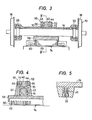
- the tapered pin means 40, 42 have a normal taper 66 which is progressively reduced from an outer end thereof toward the center and a reverse taper 68 which progressively increases from the center toward the opposite end of the pin as shown most clearly in Figures 3 and 4.
- the openings 48, 50 and the annular receiving members 52, 54 have tapers 70, 72 corresponding to the tapers 66, 68 of the tapered pin means 40, 42. Therefore, the resilient members 40, 46 have a substantially X-shaped cross-sectional configuration.
- the deformable annular resilient members 40, 46 and the tapered pins 40, 42 allow the shafts 14, 16 to move in lateral and vertical directions as well as rotating in any of three mutually perpendicular planes.
- rotation in a horizontal plane is known as yawing
- in a vertical plane perpendicular to the direction of travel is know as rowing
- in a vertical plane parallel to the direction of travel is know as pitching.
- the position of the suspending means 28, 30 and 32, 34 is not limited and may be varied to other positions disposed between the respective wheels 18, 19 and 20, 21 and the linear induction motor means 74. Moreover, since all of the weight of the linear motor apparatus is supported by the beam or U-shaped pipes 36, 38, the bending moments to the shafts 14, 16 are reduced. Furthermore, the U-shaped cross sectional configuration of the beams provide a high resistance to the bending moments.
- the suspension arrangement of the present invention may be used to support a reaction plate of the linear induction motor 76, with the linear induction motor then being mounted in the support means and/or guide rail for the motor vehicle.
Abstract
Description
- The present invention relates to a vehicle construction and, more particularly, to a motor bogie or carriage for a vehicle powered or driven by a linear motor means.
- Motor vehicles powered by linear motor drive sources have been proposed wherein a linear motor means is directly suspended from a shaft of the vehicle bogie or carriage. For this purpose, for example, pairs of suspension means such as, for example, mechanical journal bearings are mounted on shafts of the vehicle, with a primary apparatus of a linear induction motor, including an iron core and a coil unit wound on the core, being suspended. from the suspensions under a floor of the motor vehicle, and with the secondary means of the linear induction motor such as, for example, a reaction plate, being disposed on a vehicle support means such as the ground. Generally, the secondary apparatus includes an integral iron plate and aluminum plate.
- It is possible to chance a position of the primary and secondary means and, for example, when the secondary means of the linear induction motor is mounted on the carriage or bogie, the primary apparatus is arranged on the support means. When either of the primary or secondary means is rigidly suspended from the shaft means of the wheel assemblies of the carriage or bogie, a distance between the primary and secondary means remains unchanged and, consequently, the operating characteristics of the linear induction motor becomes very stable. However, when the linear motor means is rigidly mounted on the shaft means of the wheel assemblies of the bogie or carnage of the vehicle, the shaft means are prevented from rotating about their respective centers in a horizontal and vertical plane. Consequently, the ability of the carriage or bogie of the motor vehicle to follow the vehicle guide rail is disadvantageously significantly reduced.
- Moreover, as the linear motor means is suspended directly from the shaft or shafts of the carriage or bogie, considerably large bending moments act on a central portion of the shaft or shafts.
- The aim underlying the present invention essentially resides in providing a bogie or carnage for a linear induction motor driven vehicle which improves an ability of the vehicle to follow the vehicle guide rails.
- In accordance with advantageous features of the present invention, a linear induction motor powered vehicle is provided wherein a linear.motor means is suspended from at least one beam means bridged or suspended between a pair of suspension means mounted on a shaft of the bogie or carriage.
- Advantageously, in accordance with further features of the present invention, at least one universal or flexible joint means is provided for coupling the beam to the linear motor means.
- The beam means may, in accordance with the present invention, have a substantially U-shaped cross-sectional configuration and be .disposed so as to surround the shafts of wheel assemblies of the vehicle bogie or carriage.
- In accordance with additional features of the present invention, the suspending means are disposed between respective wheel means of the wheel assembly and the linear motor means.
- Preferably, the universal joint means includes a pin means mounted on the beam means, with the pin means having large diameter outer ends which progressively become smaller or taper in a direction of a center thereof, and with an annular resilient member being press fitted and configured to accommodate the taper of the pin means. A receiving means is provided having an opening configured so as to enable a press fitting about a periphery of the resilient means, with the linear motor means being fixed to the receiving means.
- The linear motor means may, in accordance with the present invention, include a coil means wound around a core of, for example, iron.
- Accordingly, it is an object of the present invention to provide a bogie or carriage for a linear induction motor powered vehicle which improves the trackability along the vehicle guide rail means.
- Another object of the present invention resides in providing a bogie or carriage for a linear induction motor powered vehicle which reduces the bending moments applied to the shaft means of the wheel assemblies of the vehicle.
- A still further object of-the present invention resides in providing the bogie or carriage for a linear induction motor driven vehicle which ensures a stable operation of the linear induction motor.
- Yet another object of the present invention resides in providing a carriage or bogie for a linear induction motor driven vehicle which is simple in construction and therefore relatively inexpensive to manufacture.
- A further object of the present invention resides in providing a carnage or bogie for a linear induction motor driven vehicle which functions realiably under all operating conditions.
- These and other objects, features, and advantages of the present invention will become more apparent from the following description when taken in connection with the accompanying drawings which show, for the purposes of illustration only, one embodiment in accordance with the present invention.
-
- Figure 1 is a plan view of a bogie or carriage for a linear induction motor driven vehicle constructed in accordance with the present invention;
- Figure 2 is a cross-sectional view taken along the line II-II in Figure I;
- Figure 3 is a cross-sectional view taken along the line III-III in Figure 1;
- Figure 4 is a cross-sectional view taken along the line Iv-IV in Figure 3; and
- Figure 5 is a cross-sectional view taken along the line V-V in Figure 1.
- Referring now to the drawings wherein like reference numerals are used throughout the various views to designate like parts and, more particularly, to Figure 1, according to this figure, wheel assemblies generally designated by the
reference numerals shafts wheels shafts - As shown in Figure 5, mechanical bearing block means 22 are mounted at respective ends of the
shafts carriage frame 24 is mounted on the bearing block means 22, with suspension spring means 26 being inserted or interposed between theframe 24 and the bearing block means 22. By virtue of the provision of the mechanical bearing block means and spring means 26, thewheel assemblies frame 24 in a vertical direction. - As shown in Figure 1, pairs of suspension means 28, 30 and 32, 34 constructed as, for example, mechanical bearing block means, are mounted at respective ends of the
shafts wheels shafts - As shown most clearly in Figures 3 and 4,
tapered pins openings 48, 50 provided in receivingmembers resilient members tapered pins openings 48, 50 provided in the receivingmembers resilient members tapered pins resilient members members reference numerals - As shown in Figures 2 and 4, the receiving
members frame 59. Aniron core 60 and a.coil unit 62, wound on thecore 60, are fixed to the supportingframe 59. - The tapered pin means 40, 42 have a
normal taper 66 which is progressively reduced from an outer end thereof toward the center and areverse taper 68 which progressively increases from the center toward the opposite end of the pin as shown most clearly in Figures 3 and 4. Moreover, theopenings 48, 50 and the annular receivingmembers tapers tapers resilient members reference numeral 74 and the supportingframe 59 is supported by thenormal tapers 66 of thetapered pins resilient members tapered pins shafts - Since the linear induction motor means 74 is not directly suspended from the
shafts means respective wheels U-shaped pipes shafts - As can readily be appreciated, the suspension arrangement of the present invention may be used to support a reaction plate of the linear induction motor 76, with the linear induction motor then being mounted in the support means and/or guide rail for the motor vehicle.
- While we have shown and described only one embodiment in accordance with the present invention, it is understood that the same is not limited thereto but is susceptible of numerous changes and modifications as known to those having ordinary skill in the art .and we therefore do not wish to be limited to the details shown and described herein, but intend to cover all such modifications as are encompassed by the scope of the appended claims.
Claims (19)
Applications Claiming Priority (2)
| Application Number | Priority Date | Filing Date | Title |
|---|---|---|---|
| JP57137365A JPS5929561A (en) | 1982-08-09 | 1982-08-09 | Truck for linear motor driving car |
| JP137365/82 | 1982-08-09 |
Publications (3)
| Publication Number | Publication Date |
|---|---|
| EP0102551A2 true EP0102551A2 (en) | 1984-03-14 |
| EP0102551A3 EP0102551A3 (en) | 1987-09-30 |
| EP0102551B1 EP0102551B1 (en) | 1991-01-30 |
Family
ID=15196971
Family Applications (1)
| Application Number | Title | Priority Date | Filing Date |
|---|---|---|---|
| EP83107849A Expired EP0102551B1 (en) | 1982-08-09 | 1983-08-09 | A motor vehicle bogie |
Country Status (5)
| Country | Link |
|---|---|
| US (1) | US4593625A (en) |
| EP (1) | EP0102551B1 (en) |
| JP (1) | JPS5929561A (en) |
| CA (1) | CA1203125A (en) |
| DE (1) | DE3382143D1 (en) |
Cited By (5)
| Publication number | Priority date | Publication date | Assignee | Title |
|---|---|---|---|---|
| EP0195644A1 (en) * | 1985-03-18 | 1986-09-24 | Shinko Electric Co. Ltd. | Truck apparatus |
| DE4322074A1 (en) * | 1993-07-02 | 1995-01-26 | Magnetbahn Gmbh | Linear motor with rotor constructed as a vehicle |
| EP1803604A2 (en) | 2005-12-23 | 2007-07-04 | Bombardier Transportation GmbH | Railway bogie provided with a linear induction motor |
| CN103171457A (en) * | 2011-12-22 | 2013-06-26 | 邦巴尔迪尔运输有限公司 | Support structure for a secondary LIM rail portion |
| LT6694B (en) | 2019-01-31 | 2020-01-27 | Fokin Aleksandr | Universal rail bogie with movement rollers |
Families Citing this family (9)
| Publication number | Priority date | Publication date | Assignee | Title |
|---|---|---|---|---|
| FR2604964B1 (en) * | 1986-10-14 | 1993-12-31 | Matra Transport | MAGNETICALLY GUIDED AXLE FOR RAILWAY VEHICLES |
| FR2754230B1 (en) * | 1996-10-07 | 2003-09-26 | Gec Alsthom Transport Sa | ARTICULATED BOGIE CHASSIS AND ARTICULATED BOGIE COMPRISING SUCH A CHASSIS |
| US6732658B1 (en) * | 2003-07-14 | 2004-05-11 | John B. Shaw | Transit car propelled by multiple pairs of magnetic linear motors |
| CN102079316B (en) * | 2010-09-07 | 2012-08-08 | 南车青岛四方机车车辆股份有限公司 | Railway vehicle linear motor bogie and manufacturing method thereof |
| CN102195394B (en) * | 2010-12-27 | 2012-11-21 | 南车青岛四方机车车辆股份有限公司 | Device and method for suspension and height adjustment of linear motor of railway vehicle |
| CN104895904B (en) * | 2015-06-12 | 2017-10-03 | 中车青岛四方机车车辆股份有限公司 | A kind of Linear motor bogie for being provided with locking rotation stop pad |
| FR3049252B1 (en) * | 2016-03-25 | 2018-04-20 | Alstom Transport Technologies | BOGIE COMPRISING A RIGID CONNECTION BETWEEN THE AXLE BOXES AND THE RAIL VEHICLE ASSOCIATED THEREWITH |
| CA2936722C (en) * | 2016-07-19 | 2017-03-07 | Bombardier Transportation Gmbh | Bogie with a motor mount for a linear induction motor |
| CN110435676A (en) * | 2019-08-07 | 2019-11-12 | 重庆交通大学 | Linear motor drives straddle-type single-track vehicle |
Citations (4)
| Publication number | Priority date | Publication date | Assignee | Title |
|---|---|---|---|---|
| US2781990A (en) * | 1952-11-19 | 1957-02-19 | Gomma Antivibranti Applic | Double acting resilient support for engine mountings |
| GB997305A (en) * | 1961-11-17 | 1965-07-07 | Metalastik Ltd | Improvements in or relating to railway vehicles |
| US3516364A (en) * | 1967-12-28 | 1970-06-23 | Mte Soc | Resilient supporting device for a railway linear motor |
| US3602149A (en) * | 1969-03-28 | 1971-08-31 | Gen Steel Ind Inc | Linear motor driven railway vehicle truck |
Family Cites Families (4)
| Publication number | Priority date | Publication date | Assignee | Title |
|---|---|---|---|---|
| US573823A (en) * | 1896-12-22 | lefpler | ||
| FR2194067B1 (en) * | 1972-07-26 | 1976-05-14 | Moyse Sa | |
| DE2443832A1 (en) * | 1974-09-13 | 1976-03-25 | Knorr Bremse Gmbh | HANGING DEVICE FOR RAIL BRAKE MAGNETS |
| CA1078936A (en) * | 1977-11-30 | 1980-06-03 | George Sobolewski | Railway truck and lim propulsion assembly |
-
1982
- 1982-08-09 JP JP57137365A patent/JPS5929561A/en active Granted
-
1983
- 1983-08-09 EP EP83107849A patent/EP0102551B1/en not_active Expired
- 1983-08-09 CA CA000434241A patent/CA1203125A/en not_active Expired
- 1983-08-09 DE DE8383107849T patent/DE3382143D1/en not_active Expired - Lifetime
- 1983-08-09 US US06/521,549 patent/US4593625A/en not_active Expired - Fee Related
Patent Citations (4)
| Publication number | Priority date | Publication date | Assignee | Title |
|---|---|---|---|---|
| US2781990A (en) * | 1952-11-19 | 1957-02-19 | Gomma Antivibranti Applic | Double acting resilient support for engine mountings |
| GB997305A (en) * | 1961-11-17 | 1965-07-07 | Metalastik Ltd | Improvements in or relating to railway vehicles |
| US3516364A (en) * | 1967-12-28 | 1970-06-23 | Mte Soc | Resilient supporting device for a railway linear motor |
| US3602149A (en) * | 1969-03-28 | 1971-08-31 | Gen Steel Ind Inc | Linear motor driven railway vehicle truck |
Cited By (5)
| Publication number | Priority date | Publication date | Assignee | Title |
|---|---|---|---|---|
| EP0195644A1 (en) * | 1985-03-18 | 1986-09-24 | Shinko Electric Co. Ltd. | Truck apparatus |
| DE4322074A1 (en) * | 1993-07-02 | 1995-01-26 | Magnetbahn Gmbh | Linear motor with rotor constructed as a vehicle |
| EP1803604A2 (en) | 2005-12-23 | 2007-07-04 | Bombardier Transportation GmbH | Railway bogie provided with a linear induction motor |
| CN103171457A (en) * | 2011-12-22 | 2013-06-26 | 邦巴尔迪尔运输有限公司 | Support structure for a secondary LIM rail portion |
| LT6694B (en) | 2019-01-31 | 2020-01-27 | Fokin Aleksandr | Universal rail bogie with movement rollers |
Also Published As
| Publication number | Publication date |
|---|---|
| DE3382143D1 (en) | 1991-03-07 |
| EP0102551B1 (en) | 1991-01-30 |
| US4593625A (en) | 1986-06-10 |
| EP0102551A3 (en) | 1987-09-30 |
| JPH0137310B2 (en) | 1989-08-07 |
| JPS5929561A (en) | 1984-02-16 |
| CA1203125A (en) | 1986-04-15 |
Similar Documents
| Publication | Publication Date | Title |
|---|---|---|
| EP0102551A2 (en) | A motor vehicle bogie | |
| US5098068A (en) | Lifting machinery | |
| EP0931684B1 (en) | Electrically driven vehicle | |
| US4398468A (en) | Railway propulsion system suspension | |
| US4526107A (en) | Railway truck for self-propelled railway vehicles | |
| US5941174A (en) | Motorized axle having wheels that rotate independently | |
| US3830166A (en) | Motorized swivel truck for rail vehicles, especially streetcars | |
| US20200385032A1 (en) | Elastic bushing device of traction device and railcar bogie | |
| US1813140A (en) | Railway motor suspension | |
| US4249627A (en) | Chassis and suspension arrangement for motor vehicles | |
| US3515405A (en) | Axle suspension system for transit vehicles | |
| JPH08253147A (en) | Variable gauge track of railway rolling stock | |
| US2987013A (en) | Vehicles | |
| EP0571961A1 (en) | A bogie for a railway vehicle with drive motors and reduction units suspended from the chassis | |
| US2336661A (en) | Rail-car truck | |
| US6253686B1 (en) | Power puller motor bogie | |
| EP3674165B1 (en) | Locomotive bogie having an anti-pitching geometry | |
| CA1109336A (en) | Railway truck; split pivotal connection | |
| US2290643A (en) | Railway truck construction | |
| CN110001410B (en) | Chassis structure and magnetic suspension track operation vehicle | |
| EP0086299A2 (en) | Improvements in or relating to vehicle transmission systems | |
| CN208453082U (en) | A kind of robot base apparatus | |
| JPS6357269B2 (en) | ||
| JP2000052979A (en) | Truck for monorail vehicle | |
| EP0471304B1 (en) | Pendulum vehicle |
Legal Events
| Date | Code | Title | Description |
|---|---|---|---|
| PUAI | Public reference made under article 153(3) epc to a published international application that has entered the european phase |
Free format text: ORIGINAL CODE: 0009012 |
|
| 17P | Request for examination filed |
Effective date: 19830816 |
|
| AK | Designated contracting states |
Designated state(s): DE FR |
|
| PUAL | Search report despatched |
Free format text: ORIGINAL CODE: 0009013 |
|
| AK | Designated contracting states |
Kind code of ref document: A3 Designated state(s): DE FR |
|
| 17Q | First examination report despatched |
Effective date: 19891218 |
|
| GRAA | (expected) grant |
Free format text: ORIGINAL CODE: 0009210 |
|
| AK | Designated contracting states |
Kind code of ref document: B1 Designated state(s): DE FR |
|
| REF | Corresponds to: |
Ref document number: 3382143 Country of ref document: DE Date of ref document: 19910307 |
|
| ET | Fr: translation filed | ||
| PLBE | No opposition filed within time limit |
Free format text: ORIGINAL CODE: 0009261 |
|
| STAA | Information on the status of an ep patent application or granted ep patent |
Free format text: STATUS: NO OPPOSITION FILED WITHIN TIME LIMIT |
|
| 26N | No opposition filed | ||
| PGFP | Annual fee paid to national office [announced via postgrant information from national office to epo] |
Ref country code: FR Payment date: 19970618 Year of fee payment: 15 |
|
| PGFP | Annual fee paid to national office [announced via postgrant information from national office to epo] |
Ref country code: DE Payment date: 19970930 Year of fee payment: 15 |
|
| PG25 | Lapsed in a contracting state [announced via postgrant information from national office to epo] |
Ref country code: FR Free format text: LAPSE BECAUSE OF NON-PAYMENT OF DUE FEES Effective date: 19990430 |
|
| PG25 | Lapsed in a contracting state [announced via postgrant information from national office to epo] |
Ref country code: DE Free format text: LAPSE BECAUSE OF NON-PAYMENT OF DUE FEES Effective date: 19990601 |
|
| REG | Reference to a national code |
Ref country code: FR Ref legal event code: ST |