EP0102106B1 - Method and device for determining the saturation temperature of a solution - Google Patents
Method and device for determining the saturation temperature of a solution Download PDFInfo
- Publication number
- EP0102106B1 EP0102106B1 EP83201100A EP83201100A EP0102106B1 EP 0102106 B1 EP0102106 B1 EP 0102106B1 EP 83201100 A EP83201100 A EP 83201100A EP 83201100 A EP83201100 A EP 83201100A EP 0102106 B1 EP0102106 B1 EP 0102106B1
- Authority
- EP
- European Patent Office
- Prior art keywords
- light
- temperature
- vessel
- photodetector
- solution
- Prior art date
- Legal status (The legal status is an assumption and is not a legal conclusion. Google has not performed a legal analysis and makes no representation as to the accuracy of the status listed.)
- Expired
Links
- 238000000034 method Methods 0.000 title claims abstract description 23
- 239000013078 crystal Substances 0.000 claims abstract description 54
- 238000005259 measurement Methods 0.000 claims abstract description 33
- 230000003247 decreasing effect Effects 0.000 claims abstract description 13
- 230000003287 optical effect Effects 0.000 claims abstract description 9
- 230000010287 polarization Effects 0.000 claims description 19
- 230000007423 decrease Effects 0.000 claims description 7
- 239000000126 substance Substances 0.000 claims description 6
- 238000004090 dissolution Methods 0.000 claims description 3
- 238000010438 heat treatment Methods 0.000 abstract description 3
- 238000012544 monitoring process Methods 0.000 abstract description 3
- 230000015572 biosynthetic process Effects 0.000 abstract description 2
- 239000000243 solution Substances 0.000 description 29
- 239000000523 sample Substances 0.000 description 5
- PAWQVTBBRAZDMG-UHFFFAOYSA-N 2-(3-bromo-2-fluorophenyl)acetic acid Chemical compound OC(=O)CC1=CC=CC(Br)=C1F PAWQVTBBRAZDMG-UHFFFAOYSA-N 0.000 description 3
- 239000012530 fluid Substances 0.000 description 3
- 238000000149 argon plasma sintering Methods 0.000 description 2
- 238000001816 cooling Methods 0.000 description 2
- 230000029087 digestion Effects 0.000 description 2
- 230000008034 disappearance Effects 0.000 description 2
- 238000002360 preparation method Methods 0.000 description 2
- GRYLNZFGIOXLOG-UHFFFAOYSA-N Nitric acid Chemical compound O[N+]([O-])=O GRYLNZFGIOXLOG-UHFFFAOYSA-N 0.000 description 1
- XSQUKJJJFZCRTK-UHFFFAOYSA-N Urea Chemical compound NC(N)=O XSQUKJJJFZCRTK-UHFFFAOYSA-N 0.000 description 1
- BVCZEBOGSOYJJT-UHFFFAOYSA-N ammonium carbamate Chemical compound [NH4+].NC([O-])=O BVCZEBOGSOYJJT-UHFFFAOYSA-N 0.000 description 1
- 239000007864 aqueous solution Substances 0.000 description 1
- 239000004202 carbamide Substances 0.000 description 1
- KXDHJXZQYSOELW-UHFFFAOYSA-N carbonic acid monoamide Natural products NC(O)=O KXDHJXZQYSOELW-UHFFFAOYSA-N 0.000 description 1
- 230000007547 defect Effects 0.000 description 1
- 239000003337 fertilizer Substances 0.000 description 1
- 238000007689 inspection Methods 0.000 description 1
- 229910017604 nitric acid Inorganic materials 0.000 description 1
- 239000002367 phosphate rock Substances 0.000 description 1
- 230000005855 radiation Effects 0.000 description 1
- 239000012488 sample solution Substances 0.000 description 1
- 239000007787 solid Substances 0.000 description 1
Images
Classifications
-
- G—PHYSICS
- G01—MEASURING; TESTING
- G01N—INVESTIGATING OR ANALYSING MATERIALS BY DETERMINING THEIR CHEMICAL OR PHYSICAL PROPERTIES
- G01N11/00—Investigating flow properties of materials, e.g. viscosity, plasticity; Analysing materials by determining flow properties
-
- G—PHYSICS
- G01—MEASURING; TESTING
- G01N—INVESTIGATING OR ANALYSING MATERIALS BY DETERMINING THEIR CHEMICAL OR PHYSICAL PROPERTIES
- G01N21/00—Investigating or analysing materials by the use of optical means, i.e. using sub-millimetre waves, infrared, visible or ultraviolet light
- G01N21/17—Systems in which incident light is modified in accordance with the properties of the material investigated
- G01N21/21—Polarisation-affecting properties
-
- G—PHYSICS
- G01—MEASURING; TESTING
- G01N—INVESTIGATING OR ANALYSING MATERIALS BY DETERMINING THEIR CHEMICAL OR PHYSICAL PROPERTIES
- G01N25/00—Investigating or analyzing materials by the use of thermal means
- G01N25/14—Investigating or analyzing materials by the use of thermal means by using distillation, extraction, sublimation, condensation, freezing, or crystallisation
- G01N25/147—Investigating or analyzing materials by the use of thermal means by using distillation, extraction, sublimation, condensation, freezing, or crystallisation by cristallisation
Definitions
- the invention relates to a method for determining the saturation temperature of a solution in which the temperature of the solution in an optical measurement vessel is gradually increased from a temperature at which the solution contains crystals of the dissolved substance to a temperature at which all crystals are dissolved, the temperature meanwhile being measured continuously, a beam of light is transmitted through the measurement vessel and the dissolution of the last crystals present is detected optically by a first photodetector.
- the object of the invention is to provide a method not having the drawbacks of the foregoing methods.
- the method according to the invention can be applied in all those cases in which the crystals of the dissolved substance are optically anisotropic, that is, in general, when the crystals are not cubic.
- the method is based on the fact that in an anisotropic crystal, placed in a beam of linearly polarized light, the polarization plane of the light transmitted through the crystal is rotated (except in the exceptional case that the crystal has an optical axis exactly parallel to the beam of light).
- the direct beam is not allowed to pass through by the analyzer, but the light of which the polarization plane has been rotated in any crystals present is partially allowed through by the analyzer, so that the photodetector behind the analyzer measures a certain light intensity. When the last crystals have dissolved, virtually no more light will reach the detector.
- the method according to the invention has the advantage that measurements can be performed in turbid solutions, because non-anisotropic parts do not interfere with the measurement.
- a light source with an optical system and a polarization filter For generating the linearly polarized beam of light, use can be made of all means usually employed for the purpose, for instance a light source with an optical system and a polarization filter. According to the invention, however, by preference use is made of a laser, with which a narrow, well-defined, accurately parallel, intensive, virtually completely linearly polarized beam of light is obtained. As analyzer use is made of, for instance, a polarization filter or a Nicol prism.
- the saturation temperature is measured as that temperature at which, upon a gradual temperature increase, the last crystals dissolve, and not the temperature at which, upon a gradual decrease in temperature, the first crystals crystallize out, as the latter temperature, because of possible oversaturation of the solution, will in many cases not be the true saturation temperature.
- the solution to be examined usually contains no crystals.
- the method according to the invention is carried out so that the solution not containing any crystals is fed to the measurement vessel, the light intensity measured by the photodetector having the said low, essentially constant value because the beam of light passes the clear solution without being hindered, but is not allowed to pass through by the analyzer.
- the temperature of the measurement vessel is gradually decreased until crystals form, and this causes the light intensity measured by the photodetector first to increase, because in the crystals being formed the polarization plane of the transmitted light is rotated so that light passes the analyzer, and subsequently to decrease to a small value, because the light is strongly scattered in the denser crystal mass.
- the temperature of the measurement vessel is gradually raised until the crystals dissolve and this causes the light intensity measured by the photodetector first to increase, namely when the light-scattering crystal mass has largely dissolved but crystals are still present in which the polarization plane of the light is rotated, and then to decrease to the low, constant value mentioned.
- the temperature at which this occurs is the saturation temperature to be determined.
- a part of the beam of light transmitted through the measurement vessel is split off, and its intensity measured with a second photodetector.
- the intensity measured by the second photodetector is low; when no crystal mass is present, this intensity is high.
- a second photodetector also provides an attractive opportunity to control the temperature of the measurement vessel, this comprising decreasing of the temperature of the measurement vessel as long as the light intensity measured by the second photodetector is at least equal to a certain high value and increasing it as long as the light intensity measured by the second photodetector is at most equal to a certain low value.
- the method according to the invention can be carried out so that it is suitable for continuously measuring and monitoring the saturation temperature of a solution, for instance a process fluid in a chemical plant, this comprising continuously leading a small sample flow of solution to be examined through the measurement vessel and, also continuously, gradually decreasing the temperature of the measurement vessel until crystals form and, alternately, increasing it until the crystals have dissolved.
- a solution for instance a process fluid in a chemical plant
- the method according to the invention proves to be very suitable for monitoring the saturation temperature of, for instance, an ammonium carbamate containing aqueous solution formed in the preparation of urea or an ammonium nitrate containing solution formed in the preparation of ammonium nitrate or ammonium nitrate containing fertilizers or a digestion liquor obtained in the digestion of rock phosphate with nitric acid.
- the invention also relates to a device for carrying out the method according to the invention for determining the saturation temperature of a solution, provided with an optical measurement vessel, means for varying the temperature of the vessel, means for continuously measuring the temperature of the solution, means for generating a beam of light transmitted through the measurement vessel, and a first photodetector for measuring the intensity of the transmitted light.
- the means for generating a linearly polarized beam of light consist substantially of a laser.
- the beam-splitting element may, for instance, be a semi-transparent mirror placed at an angle of 45° to the beam, or a divided rectangular prism, the plane of division of which has a semi-transparent mirror surface and is at an angle of 45° to the rectangular faces of the prism and to the beam.
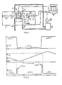
- 1 indicates a preferably light-tight cabinet in which the optical part of the device is placed.
- a solution to be examined can be supplied to optical measurement vessel 2.
- Measurement vessel 2 is provided with a heating and cooling jacket 3 with a supply 6 and a discharge 7 for cooling and heating fluid.
- the temperature of this fluid can alternately be decreased or increased, so that the solution in measurement vessel 2 is by turns cooled to below the saturation temperature and heated to above the saturation temperature.
- the solution in measurement vessel 2 is stirred continuously by means of a magnetic stirrer 9.
- a laser 10 casts a beam of linearly polarized light 11 through measurement vessel 2.
- a divided rectangular prism 14 has been placed, the plane of division 15 of which has a semi-transparent mirror surface and is at an angle of 45° to the transmitted beam.
- This prism casts part 16 of the transmitted radiation onto a photodetector 17; the remaining part of the transmitted beam falls on a polarization filter 12 of which the direction of polarization is normal to that of the beam of polarized light 11 that is generated by laser 10. If light is present which can pass this polarization filter 12, it will fall on a photodetector 13.
- the temperature of the solution in measurement vessel 2 is measured by an electrical temperature-measuring device 19, the sensitive part of which is placed as close as possible to the beam of light in vessel 2.
- the output signals of photodetectors 13 and 17 and temperature-measuring device 19 are recorded by means of a multipoint recording meter 18.
- Fig. 2 the pattern of the changes in the variables measured during a measurement cycle is presented in idealized form. Horizontally, the time t is plotted, vertically the light intensity L13 measured by photodetector 13 (bottom graph), the temperature T measured by temperature-measuring device 19 (centre graph) and the light intensity L17 measured by photodetector 17 (top graph).
- a measurement cycle comprises the following:
- the temperature of the solution is gradually increased until the crystals redissolve.
- L13 increases to a peak value L13-B and subsequently decreases, when the last crystals dissolve, to the low, constant value L13-1.
- the temperature T s at which the last crystals dissolve, is the saturation temperature to be determined.
- the determination can be carried out both discontinuously and continuously.
- vessel 2 is filled with sample solution and then closed, after which the determination is performed in the way described. Subsequently the sample is discharged, vessel 2 is, if necessary, flushed and a new sample is or is not supplied.
- a small sample flow is continuously supplied and the temperature of the solution is alternately decreased until crystals form and increased until the crystals dissolve; the amount of sample supplied per unit of time then is to be taken so small that the desired temperature programme is not interfered with.
- Signal L17 For the actual determination of the saturation temperature only signals T and L13 are used. Signal L17, however, gives a good indication of the reliability of the measurement; a deviating signal L17 may for instance point to defects or fouling of the equipment, or to the present of non- soluble, suspended solid components. Signal L17 is used to control the temperature programme of thermostat 8. In Fig. 1 this is indicated by the broken lines; a programmer 20 controls thermostat 8 in such a way that the temperature of the measurement vessel 2 is decreased as along as signal L17 has the high value L17-1 and increased when the signal L17 has the low value L17-2.
Landscapes
- Physics & Mathematics (AREA)
- Health & Medical Sciences (AREA)
- Life Sciences & Earth Sciences (AREA)
- Chemical & Material Sciences (AREA)
- Analytical Chemistry (AREA)
- Biochemistry (AREA)
- General Health & Medical Sciences (AREA)
- General Physics & Mathematics (AREA)
- Immunology (AREA)
- Pathology (AREA)
- Investigating Or Analysing Materials By Optical Means (AREA)
- Investigating Or Analyzing Materials Using Thermal Means (AREA)
- Measuring Temperature Or Quantity Of Heat (AREA)
- Organic Low-Molecular-Weight Compounds And Preparation Thereof (AREA)
Priority Applications (1)
| Application Number | Priority Date | Filing Date | Title |
|---|---|---|---|
| AT83201100T ATE30474T1 (de) | 1982-07-28 | 1983-07-27 | Verfahren und einrichtung zur bestimmung der saturationstemperatur einer loesung. |
Applications Claiming Priority (2)
| Application Number | Priority Date | Filing Date | Title |
|---|---|---|---|
| NL8203013 | 1982-07-28 | ||
| NL8203013A NL8203013A (nl) | 1982-07-28 | 1982-07-28 | Werkwijze en inrichting voor het bepalen van de verzadigingstemperatuur van een oplossing. |
Publications (2)
| Publication Number | Publication Date |
|---|---|
| EP0102106A1 EP0102106A1 (en) | 1984-03-07 |
| EP0102106B1 true EP0102106B1 (en) | 1987-10-28 |
Family
ID=19840085
Family Applications (1)
| Application Number | Title | Priority Date | Filing Date |
|---|---|---|---|
| EP83201100A Expired EP0102106B1 (en) | 1982-07-28 | 1983-07-27 | Method and device for determining the saturation temperature of a solution |
Country Status (10)
| Country | Link |
|---|---|
| US (1) | US4572676A (enExample) |
| EP (1) | EP0102106B1 (enExample) |
| JP (1) | JPS59107248A (enExample) |
| KR (1) | KR870001228B1 (enExample) |
| AT (1) | ATE30474T1 (enExample) |
| CA (1) | CA1208033A (enExample) |
| DE (1) | DE3374220D1 (enExample) |
| IN (1) | IN157046B (enExample) |
| NL (1) | NL8203013A (enExample) |
| SU (1) | SU1364248A3 (enExample) |
Families Citing this family (11)
| Publication number | Priority date | Publication date | Assignee | Title |
|---|---|---|---|---|
| FR2586479B1 (fr) * | 1985-08-22 | 1987-12-18 | Elf France | Procede et application pour la determination des points de trouble et d'ecoulement |
| US4804274A (en) * | 1986-12-30 | 1989-02-14 | Mobil Oil Corporation | Method and apparatus for determining phase transition temperature using laser attenuation |
| US4886354A (en) * | 1988-05-06 | 1989-12-12 | Conoco Inc. | Method and apparatus for measuring crystal formation |
| JPH03140840A (ja) * | 1989-10-26 | 1991-06-14 | Hitachi Ltd | 流動細胞分析装置 |
| DE4340383C2 (de) * | 1993-08-05 | 1995-05-18 | Alfons Prof Dr Ing Mersmann | Verfahren zur Messung der Übersättigung von Lösungen fester Stoffe in Flüssigkeiten |
| US5758968A (en) * | 1996-07-15 | 1998-06-02 | Digimelt Inc. | Optically based method and apparatus for detecting a phase transition temperature of a material of interest |
| AU2001238147A1 (en) * | 2000-02-10 | 2001-08-20 | The Regents Of The University Of California | Method and apparatus for measuring birefringent particles |
| US6604852B1 (en) * | 2000-12-09 | 2003-08-12 | Halliburton Energy Services, Inc. | High pressure brine crystallization point apparatus |
| FR2846748B1 (fr) * | 2002-10-30 | 2005-04-22 | I S L | Procede de determination du point de disparition des cristaux de produits petroliers ainsi que dispositif permettant la mise en oeuvre de ce procede |
| CA2623216A1 (en) | 2005-09-22 | 2007-03-29 | Avantium International B.V. | System and method for solubility curve and metastable zone determination |
| CN108489629B (zh) * | 2018-06-20 | 2024-01-05 | 山东大学 | 一种溶液饱和温度自动测量装置及测量方法 |
Family Cites Families (16)
| Publication number | Priority date | Publication date | Assignee | Title |
|---|---|---|---|---|
| US2716371A (en) * | 1950-05-22 | 1955-08-30 | Gen Electric Co Ltd | Apparatus for measuring the saturation temperature of solutions |
| US3026710A (en) * | 1956-10-01 | 1962-03-27 | Phillips Petroleum Co | Ammonium nitrate analysis and control |
| US3008324A (en) * | 1957-09-25 | 1961-11-14 | Standard Oil Co | Low temperature cloud point apparatus |
| US3060318A (en) * | 1960-11-28 | 1962-10-23 | Antar Petroles Atlantique | Method and apparatus for the testing of fluids |
| NL287768A (enExample) * | 1962-02-05 | |||
| US3283644A (en) * | 1962-11-27 | 1966-11-08 | Du Pont | Apparatus for determining the concentration of dispersed particulate solids in liquids |
| US3354317A (en) * | 1964-08-17 | 1967-11-21 | Exxon Research Engineering Co | Radiation sensitive apparatus and method for analyzing molecular weight distribution in polymeric material |
| FR1417250A (fr) * | 1964-09-28 | 1965-11-12 | Cie De Raffinage Shell Berre | Procédé et appareil pour la mesure du point de trouble de liquides |
| US3545254A (en) * | 1968-02-13 | 1970-12-08 | Shell Oil Co | Cloud point detector |
| US3540826A (en) * | 1968-06-06 | 1970-11-17 | Eg & G Inc | Saturation hygrometer |
| US3807865A (en) * | 1970-12-18 | 1974-04-30 | M Gordon | Process and apparatus for determination of spinodal and critical points or loci associated with phase transition |
| ZA721510B (en) * | 1972-03-06 | 1974-01-30 | African Explosives & Chem | Method of and apparatus for determining the concentration of a solution |
| IL43465A (en) * | 1973-10-23 | 1976-12-31 | Yeda Res & Dev | Gem identification |
| JPS6057019B2 (ja) * | 1980-02-18 | 1985-12-12 | 日本甜菜製糖株式会社 | 飽和温度測定用試料の調製方法 |
| US4377001A (en) * | 1979-10-29 | 1983-03-15 | Nippon Tensaiseito Kabushiki Kaisha | Method for optical determination of saturation temperature and apparatus therefor |
| US4519717A (en) * | 1982-06-07 | 1985-05-28 | Gca Corporation | On-stream cloud point analyzer |
-
1982
- 1982-07-28 NL NL8203013A patent/NL8203013A/nl not_active Application Discontinuation
-
1983
- 1983-07-20 US US06/515,502 patent/US4572676A/en not_active Expired - Fee Related
- 1983-07-20 IN IN905/CAL/83A patent/IN157046B/en unknown
- 1983-07-25 KR KR1019830003475A patent/KR870001228B1/ko not_active Expired
- 1983-07-26 SU SU833625383A patent/SU1364248A3/ru active
- 1983-07-27 JP JP58136037A patent/JPS59107248A/ja active Pending
- 1983-07-27 CA CA000433325A patent/CA1208033A/en not_active Expired
- 1983-07-27 DE DE8383201100T patent/DE3374220D1/de not_active Expired
- 1983-07-27 AT AT83201100T patent/ATE30474T1/de active
- 1983-07-27 EP EP83201100A patent/EP0102106B1/en not_active Expired
Also Published As
| Publication number | Publication date |
|---|---|
| KR840005556A (ko) | 1984-11-14 |
| US4572676A (en) | 1986-02-25 |
| KR870001228B1 (ko) | 1987-06-22 |
| IN157046B (enExample) | 1986-01-04 |
| NL8203013A (nl) | 1984-02-16 |
| ATE30474T1 (de) | 1987-11-15 |
| DE3374220D1 (en) | 1987-12-03 |
| JPS59107248A (ja) | 1984-06-21 |
| CA1208033A (en) | 1986-07-22 |
| SU1364248A3 (ru) | 1987-12-30 |
| EP0102106A1 (en) | 1984-03-07 |
Similar Documents
| Publication | Publication Date | Title |
|---|---|---|
| EP0102106B1 (en) | Method and device for determining the saturation temperature of a solution | |
| Magill | A new method for following rapid rates of crystallization I. Poly (hexamethylene adipamide) | |
| US4672218A (en) | Method for determining the onset of crystallization | |
| Kask et al. | Fluorescence correlation spectroscopy in the nanosecond time range: rotational diffusion of bovine carbonic anhydrase B | |
| Chang et al. | Self-diffusion of gelatin by forced Rayleigh scattering | |
| US3012467A (en) | Spectrum analyzer | |
| US3967902A (en) | Method and apparatus for investigating the conformation of optically active molecules by measuring parameters associated with their luminescence | |
| JPS6060729A (ja) | 洗浄装置 | |
| JPH05254983A (ja) | 溶解物レベルの検出装置及び検出方法 | |
| US4637726A (en) | Nondestructive noncontact device to characterize semiconductor material | |
| JPH05111602A (ja) | 晶析装置およびその方法 | |
| CN208520494U (zh) | 一种溶液饱和温度自动测量装置 | |
| RU2055348C1 (ru) | Способ определения примесей в растворе технической аскорбиновой кислоты | |
| SU1224766A1 (ru) | Способ контрол эффективной толщины планарного оптического волновода | |
| Rashkovich et al. | New optical interference methods for studying the kinetics of crystallization in solution | |
| SU1290098A1 (ru) | Сигнализатор температуры | |
| RU1119402C (ru) | Способ измерения прироста оптических анизотропных кристаллов в кристаллизаторе | |
| Lavorel et al. | A new method of fluorescence polarization measurement | |
| SU672549A1 (ru) | Способ измерени величины циркул рного дихроизма в кристаллах | |
| RU2024826C1 (ru) | Устройство для измерения коэффициентов поглощения и рассеяния ик-излучения | |
| Martin et al. | The Detection of Salting‐out. A Comparative Study | |
| RU1800341C (ru) | Способ определени температуры кристаллизации жидких веществ | |
| KR101094346B1 (ko) | 결정성장속도 측정방법 및 이를 위한 결정성장속도 측정장치 | |
| Le Captain | Development of second harmonic generation as a tool for monitoring crystallization | |
| JPS63186126A (ja) | 動的散乱光検出装置 |
Legal Events
| Date | Code | Title | Description |
|---|---|---|---|
| PUAI | Public reference made under article 153(3) epc to a published international application that has entered the european phase |
Free format text: ORIGINAL CODE: 0009012 |
|
| AK | Designated contracting states |
Designated state(s): AT BE DE FR GB IT NL |
|
| 17P | Request for examination filed |
Effective date: 19840808 |
|
| RAP1 | Party data changed (applicant data changed or rights of an application transferred) |
Owner name: STAMICARBON B.V. |
|
| GRAA | (expected) grant |
Free format text: ORIGINAL CODE: 0009210 |
|
| AK | Designated contracting states |
Kind code of ref document: B1 Designated state(s): AT BE DE FR GB IT NL |
|
| PG25 | Lapsed in a contracting state [announced via postgrant information from national office to epo] |
Ref country code: NL Effective date: 19871028 Ref country code: IT Free format text: LAPSE BECAUSE OF FAILURE TO SUBMIT A TRANSLATION OF THE DESCRIPTION OR TO PAY THE FEE WITHIN THE PRESCRIBED TIME-LIMIT;WARNING: LAPSES OF ITALIAN PATENTS WITH EFFECTIVE DATE BEFORE 2007 MAY HAVE OCCURRED AT ANY TIME BEFORE 2007. THE CORRECT EFFECTIVE DATE MAY BE DIFFERENT FROM THE ONE RECORDED. Effective date: 19871028 Ref country code: FR Free format text: THE PATENT HAS BEEN ANNULLED BY A DECISION OF A NATIONAL AUTHORITY Effective date: 19871028 Ref country code: BE Effective date: 19871028 Ref country code: AT Effective date: 19871028 |
|
| REF | Corresponds to: |
Ref document number: 30474 Country of ref document: AT Date of ref document: 19871115 Kind code of ref document: T |
|
| REF | Corresponds to: |
Ref document number: 3374220 Country of ref document: DE Date of ref document: 19871203 |
|
| EN | Fr: translation not filed | ||
| NLV1 | Nl: lapsed or annulled due to failure to fulfill the requirements of art. 29p and 29m of the patents act | ||
| PG25 | Lapsed in a contracting state [announced via postgrant information from national office to epo] |
Ref country code: GB Effective date: 19880727 |
|
| PLBE | No opposition filed within time limit |
Free format text: ORIGINAL CODE: 0009261 |
|
| STAA | Information on the status of an ep patent application or granted ep patent |
Free format text: STATUS: NO OPPOSITION FILED WITHIN TIME LIMIT |
|
| 26N | No opposition filed | ||
| GBPC | Gb: european patent ceased through non-payment of renewal fee | ||
| PG25 | Lapsed in a contracting state [announced via postgrant information from national office to epo] |
Ref country code: DE Effective date: 19890401 |