EP0102087B1 - Process for liquefying methane - Google Patents
Process for liquefying methane Download PDFInfo
- Publication number
- EP0102087B1 EP0102087B1 EP83108546A EP83108546A EP0102087B1 EP 0102087 B1 EP0102087 B1 EP 0102087B1 EP 83108546 A EP83108546 A EP 83108546A EP 83108546 A EP83108546 A EP 83108546A EP 0102087 B1 EP0102087 B1 EP 0102087B1
- Authority
- EP
- European Patent Office
- Prior art keywords
- stream
- feed
- methane
- refrigerant
- overhead
- Prior art date
- Legal status (The legal status is an assumption and is not a legal conclusion. Google has not performed a legal analysis and makes no representation as to the accuracy of the status listed.)
- Expired
Links
- VNWKTOKETHGBQD-UHFFFAOYSA-N methane Chemical compound C VNWKTOKETHGBQD-UHFFFAOYSA-N 0.000 title claims description 280
- 238000000034 method Methods 0.000 title claims description 37
- 230000008569 process Effects 0.000 title claims description 37
- 239000003507 refrigerant Substances 0.000 claims description 126
- 238000005057 refrigeration Methods 0.000 claims description 61
- 150000002430 hydrocarbons Chemical class 0.000 claims description 52
- 229930195733 hydrocarbon Natural products 0.000 claims description 51
- 239000003345 natural gas Substances 0.000 claims description 50
- 239000007788 liquid Substances 0.000 claims description 36
- 239000012071 phase Substances 0.000 claims description 24
- 238000010992 reflux Methods 0.000 claims description 20
- 239000003949 liquefied natural gas Substances 0.000 claims description 19
- 238000000926 separation method Methods 0.000 claims description 18
- 238000001816 cooling Methods 0.000 claims description 16
- 239000007791 liquid phase Substances 0.000 claims description 11
- 230000006835 compression Effects 0.000 claims description 10
- 238000007906 compression Methods 0.000 claims description 10
- 239000000446 fuel Substances 0.000 claims description 10
- 238000004519 manufacturing process Methods 0.000 claims description 9
- 238000003860 storage Methods 0.000 claims description 6
- FGUUSXIOTUKUDN-IBGZPJMESA-N C1(=CC=CC=C1)N1C2=C(NC([C@H](C1)NC=1OC(=NN=1)C1=CC=CC=C1)=O)C=CC=C2 Chemical compound C1(=CC=CC=C1)N1C2=C(NC([C@H](C1)NC=1OC(=NN=1)C1=CC=CC=C1)=O)C=CC=C2 FGUUSXIOTUKUDN-IBGZPJMESA-N 0.000 claims 1
- 239000007792 gaseous phase Substances 0.000 claims 1
- ATUOYWHBWRKTHZ-UHFFFAOYSA-N Propane Chemical compound CCC ATUOYWHBWRKTHZ-UHFFFAOYSA-N 0.000 description 26
- 230000008901 benefit Effects 0.000 description 20
- 239000007789 gas Substances 0.000 description 20
- 239000004215 Carbon black (E152) Substances 0.000 description 19
- 238000011084 recovery Methods 0.000 description 15
- 230000009467 reduction Effects 0.000 description 15
- 239000000047 product Substances 0.000 description 14
- OTMSDBZUPAUEDD-UHFFFAOYSA-N Ethane Chemical compound CC OTMSDBZUPAUEDD-UHFFFAOYSA-N 0.000 description 13
- 239000001294 propane Substances 0.000 description 13
- IJGRMHOSHXDMSA-UHFFFAOYSA-N Atomic nitrogen Chemical compound N#N IJGRMHOSHXDMSA-UHFFFAOYSA-N 0.000 description 12
- 238000004821 distillation Methods 0.000 description 12
- XLYOFNOQVPJJNP-UHFFFAOYSA-N water Substances O XLYOFNOQVPJJNP-UHFFFAOYSA-N 0.000 description 12
- 239000012808 vapor phase Substances 0.000 description 11
- NNPPMTNAJDCUHE-UHFFFAOYSA-N isobutane Chemical compound CC(C)C NNPPMTNAJDCUHE-UHFFFAOYSA-N 0.000 description 8
- 238000005194 fractionation Methods 0.000 description 7
- OFBQJSOFQDEBGM-UHFFFAOYSA-N n-pentane Natural products CCCCC OFBQJSOFQDEBGM-UHFFFAOYSA-N 0.000 description 6
- 229910052757 nitrogen Inorganic materials 0.000 description 6
- 239000001273 butane Substances 0.000 description 4
- 238000010586 diagram Methods 0.000 description 4
- 239000001282 iso-butane Substances 0.000 description 4
- IJDNQMDRQITEOD-UHFFFAOYSA-N n-butane Chemical compound CCCC IJDNQMDRQITEOD-UHFFFAOYSA-N 0.000 description 4
- UHOVQNZJYSORNB-UHFFFAOYSA-N Benzene Chemical compound C1=CC=CC=C1 UHOVQNZJYSORNB-UHFFFAOYSA-N 0.000 description 3
- 230000006872 improvement Effects 0.000 description 3
- 239000007921 spray Substances 0.000 description 3
- CURLTUGMZLYLDI-UHFFFAOYSA-N Carbon dioxide Chemical compound O=C=O CURLTUGMZLYLDI-UHFFFAOYSA-N 0.000 description 2
- IMNFDUFMRHMDMM-UHFFFAOYSA-N N-Heptane Chemical compound CCCCCCC IMNFDUFMRHMDMM-UHFFFAOYSA-N 0.000 description 2
- 239000012530 fluid Substances 0.000 description 2
- QWTDNUCVQCZILF-UHFFFAOYSA-N isopentane Chemical compound CCC(C)C QWTDNUCVQCZILF-UHFFFAOYSA-N 0.000 description 2
- 239000012263 liquid product Substances 0.000 description 2
- 239000000203 mixture Substances 0.000 description 2
- 238000005191 phase separation Methods 0.000 description 2
- 238000011064 split stream procedure Methods 0.000 description 2
- JKTORXLUQLQJCM-UHFFFAOYSA-N 4-phosphonobutylphosphonic acid Chemical compound OP(O)(=O)CCCCP(O)(O)=O JKTORXLUQLQJCM-UHFFFAOYSA-N 0.000 description 1
- 230000002745 absorbent Effects 0.000 description 1
- 239000002250 absorbent Substances 0.000 description 1
- 230000001154 acute effect Effects 0.000 description 1
- 230000006978 adaptation Effects 0.000 description 1
- 230000004075 alteration Effects 0.000 description 1
- 230000009286 beneficial effect Effects 0.000 description 1
- 229910002092 carbon dioxide Inorganic materials 0.000 description 1
- 239000001569 carbon dioxide Substances 0.000 description 1
- 230000008859 change Effects 0.000 description 1
- 230000002860 competitive effect Effects 0.000 description 1
- 230000001419 dependent effect Effects 0.000 description 1
- AFABGHUZZDYHJO-UHFFFAOYSA-N dimethyl butane Natural products CCCC(C)C AFABGHUZZDYHJO-UHFFFAOYSA-N 0.000 description 1
- 230000000694 effects Effects 0.000 description 1
- 230000008030 elimination Effects 0.000 description 1
- 238000003379 elimination reaction Methods 0.000 description 1
- 239000002737 fuel gas Substances 0.000 description 1
- 238000005304 joining Methods 0.000 description 1
- 239000000463 material Substances 0.000 description 1
- 239000012188 paraffin wax Substances 0.000 description 1
- 238000005086 pumping Methods 0.000 description 1
- 238000004064 recycling Methods 0.000 description 1
- 238000010792 warming Methods 0.000 description 1
Images


Classifications
-
- F—MECHANICAL ENGINEERING; LIGHTING; HEATING; WEAPONS; BLASTING
- F25—REFRIGERATION OR COOLING; COMBINED HEATING AND REFRIGERATION SYSTEMS; HEAT PUMP SYSTEMS; MANUFACTURE OR STORAGE OF ICE; LIQUEFACTION SOLIDIFICATION OF GASES
- F25J—LIQUEFACTION, SOLIDIFICATION OR SEPARATION OF GASES OR GASEOUS OR LIQUEFIED GASEOUS MIXTURES BY PRESSURE AND COLD TREATMENT OR BY BRINGING THEM INTO THE SUPERCRITICAL STATE
- F25J3/00—Processes or apparatus for separating the constituents of gaseous or liquefied gaseous mixtures involving the use of liquefaction or solidification
- F25J3/02—Processes or apparatus for separating the constituents of gaseous or liquefied gaseous mixtures involving the use of liquefaction or solidification by rectification, i.e. by continuous interchange of heat and material between a vapour stream and a liquid stream
- F25J3/0228—Processes or apparatus for separating the constituents of gaseous or liquefied gaseous mixtures involving the use of liquefaction or solidification by rectification, i.e. by continuous interchange of heat and material between a vapour stream and a liquid stream characterised by the separated product stream
- F25J3/0238—Processes or apparatus for separating the constituents of gaseous or liquefied gaseous mixtures involving the use of liquefaction or solidification by rectification, i.e. by continuous interchange of heat and material between a vapour stream and a liquid stream characterised by the separated product stream separation of CnHm with 2 carbon atoms or more
-
- F—MECHANICAL ENGINEERING; LIGHTING; HEATING; WEAPONS; BLASTING
- F25—REFRIGERATION OR COOLING; COMBINED HEATING AND REFRIGERATION SYSTEMS; HEAT PUMP SYSTEMS; MANUFACTURE OR STORAGE OF ICE; LIQUEFACTION SOLIDIFICATION OF GASES
- F25J—LIQUEFACTION, SOLIDIFICATION OR SEPARATION OF GASES OR GASEOUS OR LIQUEFIED GASEOUS MIXTURES BY PRESSURE AND COLD TREATMENT OR BY BRINGING THEM INTO THE SUPERCRITICAL STATE
- F25J1/00—Processes or apparatus for liquefying or solidifying gases or gaseous mixtures
- F25J1/0002—Processes or apparatus for liquefying or solidifying gases or gaseous mixtures characterised by the fluid to be liquefied
- F25J1/0022—Hydrocarbons, e.g. natural gas
-
- F—MECHANICAL ENGINEERING; LIGHTING; HEATING; WEAPONS; BLASTING
- F25—REFRIGERATION OR COOLING; COMBINED HEATING AND REFRIGERATION SYSTEMS; HEAT PUMP SYSTEMS; MANUFACTURE OR STORAGE OF ICE; LIQUEFACTION SOLIDIFICATION OF GASES
- F25J—LIQUEFACTION, SOLIDIFICATION OR SEPARATION OF GASES OR GASEOUS OR LIQUEFIED GASEOUS MIXTURES BY PRESSURE AND COLD TREATMENT OR BY BRINGING THEM INTO THE SUPERCRITICAL STATE
- F25J1/00—Processes or apparatus for liquefying or solidifying gases or gaseous mixtures
- F25J1/003—Processes or apparatus for liquefying or solidifying gases or gaseous mixtures characterised by the kind of cold generation within the liquefaction unit for compensating heat leaks and liquid production
- F25J1/0032—Processes or apparatus for liquefying or solidifying gases or gaseous mixtures characterised by the kind of cold generation within the liquefaction unit for compensating heat leaks and liquid production using the feed stream itself or separated fractions from it, i.e. "internal refrigeration"
- F25J1/0035—Processes or apparatus for liquefying or solidifying gases or gaseous mixtures characterised by the kind of cold generation within the liquefaction unit for compensating heat leaks and liquid production using the feed stream itself or separated fractions from it, i.e. "internal refrigeration" by gas expansion with extraction of work
-
- F—MECHANICAL ENGINEERING; LIGHTING; HEATING; WEAPONS; BLASTING
- F25—REFRIGERATION OR COOLING; COMBINED HEATING AND REFRIGERATION SYSTEMS; HEAT PUMP SYSTEMS; MANUFACTURE OR STORAGE OF ICE; LIQUEFACTION SOLIDIFICATION OF GASES
- F25J—LIQUEFACTION, SOLIDIFICATION OR SEPARATION OF GASES OR GASEOUS OR LIQUEFIED GASEOUS MIXTURES BY PRESSURE AND COLD TREATMENT OR BY BRINGING THEM INTO THE SUPERCRITICAL STATE
- F25J1/00—Processes or apparatus for liquefying or solidifying gases or gaseous mixtures
- F25J1/003—Processes or apparatus for liquefying or solidifying gases or gaseous mixtures characterised by the kind of cold generation within the liquefaction unit for compensating heat leaks and liquid production
- F25J1/0047—Processes or apparatus for liquefying or solidifying gases or gaseous mixtures characterised by the kind of cold generation within the liquefaction unit for compensating heat leaks and liquid production using an "external" refrigerant stream in a closed vapor compression cycle
- F25J1/0052—Processes or apparatus for liquefying or solidifying gases or gaseous mixtures characterised by the kind of cold generation within the liquefaction unit for compensating heat leaks and liquid production using an "external" refrigerant stream in a closed vapor compression cycle by vaporising a liquid refrigerant stream
- F25J1/0055—Processes or apparatus for liquefying or solidifying gases or gaseous mixtures characterised by the kind of cold generation within the liquefaction unit for compensating heat leaks and liquid production using an "external" refrigerant stream in a closed vapor compression cycle by vaporising a liquid refrigerant stream originating from an incorporated cascade
-
- F—MECHANICAL ENGINEERING; LIGHTING; HEATING; WEAPONS; BLASTING
- F25—REFRIGERATION OR COOLING; COMBINED HEATING AND REFRIGERATION SYSTEMS; HEAT PUMP SYSTEMS; MANUFACTURE OR STORAGE OF ICE; LIQUEFACTION SOLIDIFICATION OF GASES
- F25J—LIQUEFACTION, SOLIDIFICATION OR SEPARATION OF GASES OR GASEOUS OR LIQUEFIED GASEOUS MIXTURES BY PRESSURE AND COLD TREATMENT OR BY BRINGING THEM INTO THE SUPERCRITICAL STATE
- F25J1/00—Processes or apparatus for liquefying or solidifying gases or gaseous mixtures
- F25J1/02—Processes or apparatus for liquefying or solidifying gases or gaseous mixtures requiring the use of refrigeration, e.g. of helium or hydrogen ; Details and kind of the refrigeration system used; Integration with other units or processes; Controlling aspects of the process
- F25J1/0211—Processes or apparatus for liquefying or solidifying gases or gaseous mixtures requiring the use of refrigeration, e.g. of helium or hydrogen ; Details and kind of the refrigeration system used; Integration with other units or processes; Controlling aspects of the process using a multi-component refrigerant [MCR] fluid in a closed vapor compression cycle
- F25J1/0214—Processes or apparatus for liquefying or solidifying gases or gaseous mixtures requiring the use of refrigeration, e.g. of helium or hydrogen ; Details and kind of the refrigeration system used; Integration with other units or processes; Controlling aspects of the process using a multi-component refrigerant [MCR] fluid in a closed vapor compression cycle as a dual level refrigeration cascade with at least one MCR cycle
- F25J1/0215—Processes or apparatus for liquefying or solidifying gases or gaseous mixtures requiring the use of refrigeration, e.g. of helium or hydrogen ; Details and kind of the refrigeration system used; Integration with other units or processes; Controlling aspects of the process using a multi-component refrigerant [MCR] fluid in a closed vapor compression cycle as a dual level refrigeration cascade with at least one MCR cycle with one SCR cycle
- F25J1/0216—Processes or apparatus for liquefying or solidifying gases or gaseous mixtures requiring the use of refrigeration, e.g. of helium or hydrogen ; Details and kind of the refrigeration system used; Integration with other units or processes; Controlling aspects of the process using a multi-component refrigerant [MCR] fluid in a closed vapor compression cycle as a dual level refrigeration cascade with at least one MCR cycle with one SCR cycle using a C3 pre-cooling cycle
-
- F—MECHANICAL ENGINEERING; LIGHTING; HEATING; WEAPONS; BLASTING
- F25—REFRIGERATION OR COOLING; COMBINED HEATING AND REFRIGERATION SYSTEMS; HEAT PUMP SYSTEMS; MANUFACTURE OR STORAGE OF ICE; LIQUEFACTION SOLIDIFICATION OF GASES
- F25J—LIQUEFACTION, SOLIDIFICATION OR SEPARATION OF GASES OR GASEOUS OR LIQUEFIED GASEOUS MIXTURES BY PRESSURE AND COLD TREATMENT OR BY BRINGING THEM INTO THE SUPERCRITICAL STATE
- F25J1/00—Processes or apparatus for liquefying or solidifying gases or gaseous mixtures
- F25J1/02—Processes or apparatus for liquefying or solidifying gases or gaseous mixtures requiring the use of refrigeration, e.g. of helium or hydrogen ; Details and kind of the refrigeration system used; Integration with other units or processes; Controlling aspects of the process
- F25J1/0228—Coupling of the liquefaction unit to other units or processes, so-called integrated processes
- F25J1/0235—Heat exchange integration
- F25J1/0237—Heat exchange integration integrating refrigeration provided for liquefaction and purification/treatment of the gas to be liquefied, e.g. heavy hydrocarbon removal from natural gas
- F25J1/0238—Purification or treatment step is integrated within one refrigeration cycle only, i.e. the same or single refrigeration cycle provides feed gas cooling (if present) and overhead gas cooling
-
- F—MECHANICAL ENGINEERING; LIGHTING; HEATING; WEAPONS; BLASTING
- F25—REFRIGERATION OR COOLING; COMBINED HEATING AND REFRIGERATION SYSTEMS; HEAT PUMP SYSTEMS; MANUFACTURE OR STORAGE OF ICE; LIQUEFACTION SOLIDIFICATION OF GASES
- F25J—LIQUEFACTION, SOLIDIFICATION OR SEPARATION OF GASES OR GASEOUS OR LIQUEFIED GASEOUS MIXTURES BY PRESSURE AND COLD TREATMENT OR BY BRINGING THEM INTO THE SUPERCRITICAL STATE
- F25J1/00—Processes or apparatus for liquefying or solidifying gases or gaseous mixtures
- F25J1/02—Processes or apparatus for liquefying or solidifying gases or gaseous mixtures requiring the use of refrigeration, e.g. of helium or hydrogen ; Details and kind of the refrigeration system used; Integration with other units or processes; Controlling aspects of the process
- F25J1/0228—Coupling of the liquefaction unit to other units or processes, so-called integrated processes
- F25J1/0235—Heat exchange integration
- F25J1/0237—Heat exchange integration integrating refrigeration provided for liquefaction and purification/treatment of the gas to be liquefied, e.g. heavy hydrocarbon removal from natural gas
- F25J1/0239—Purification or treatment step being integrated between two refrigeration cycles of a refrigeration cascade, i.e. first cycle providing feed gas cooling and second cycle providing overhead gas cooling
-
- F—MECHANICAL ENGINEERING; LIGHTING; HEATING; WEAPONS; BLASTING
- F25—REFRIGERATION OR COOLING; COMBINED HEATING AND REFRIGERATION SYSTEMS; HEAT PUMP SYSTEMS; MANUFACTURE OR STORAGE OF ICE; LIQUEFACTION SOLIDIFICATION OF GASES
- F25J—LIQUEFACTION, SOLIDIFICATION OR SEPARATION OF GASES OR GASEOUS OR LIQUEFIED GASEOUS MIXTURES BY PRESSURE AND COLD TREATMENT OR BY BRINGING THEM INTO THE SUPERCRITICAL STATE
- F25J1/00—Processes or apparatus for liquefying or solidifying gases or gaseous mixtures
- F25J1/02—Processes or apparatus for liquefying or solidifying gases or gaseous mixtures requiring the use of refrigeration, e.g. of helium or hydrogen ; Details and kind of the refrigeration system used; Integration with other units or processes; Controlling aspects of the process
- F25J1/0243—Start-up or control of the process; Details of the apparatus used; Details of the refrigerant compression system used
- F25J1/0257—Construction and layout of liquefaction equipments, e.g. valves, machines
- F25J1/0262—Details of the cold heat exchange system
- F25J1/0264—Arrangement of heat exchanger cores in parallel with different functions, e.g. different cooling streams
- F25J1/0265—Arrangement of heat exchanger cores in parallel with different functions, e.g. different cooling streams comprising cores associated exclusively with the cooling of a refrigerant stream, e.g. for auto-refrigeration or economizer
- F25J1/0267—Arrangement of heat exchanger cores in parallel with different functions, e.g. different cooling streams comprising cores associated exclusively with the cooling of a refrigerant stream, e.g. for auto-refrigeration or economizer using flash gas as heat sink
-
- F—MECHANICAL ENGINEERING; LIGHTING; HEATING; WEAPONS; BLASTING
- F25—REFRIGERATION OR COOLING; COMBINED HEATING AND REFRIGERATION SYSTEMS; HEAT PUMP SYSTEMS; MANUFACTURE OR STORAGE OF ICE; LIQUEFACTION SOLIDIFICATION OF GASES
- F25J—LIQUEFACTION, SOLIDIFICATION OR SEPARATION OF GASES OR GASEOUS OR LIQUEFIED GASEOUS MIXTURES BY PRESSURE AND COLD TREATMENT OR BY BRINGING THEM INTO THE SUPERCRITICAL STATE
- F25J1/00—Processes or apparatus for liquefying or solidifying gases or gaseous mixtures
- F25J1/02—Processes or apparatus for liquefying or solidifying gases or gaseous mixtures requiring the use of refrigeration, e.g. of helium or hydrogen ; Details and kind of the refrigeration system used; Integration with other units or processes; Controlling aspects of the process
- F25J1/0243—Start-up or control of the process; Details of the apparatus used; Details of the refrigerant compression system used
- F25J1/0279—Compression of refrigerant or internal recycle fluid, e.g. kind of compressor, accumulator, suction drum etc.
- F25J1/0292—Refrigerant compression by cold or cryogenic suction of the refrigerant gas
-
- F—MECHANICAL ENGINEERING; LIGHTING; HEATING; WEAPONS; BLASTING
- F25—REFRIGERATION OR COOLING; COMBINED HEATING AND REFRIGERATION SYSTEMS; HEAT PUMP SYSTEMS; MANUFACTURE OR STORAGE OF ICE; LIQUEFACTION SOLIDIFICATION OF GASES
- F25J—LIQUEFACTION, SOLIDIFICATION OR SEPARATION OF GASES OR GASEOUS OR LIQUEFIED GASEOUS MIXTURES BY PRESSURE AND COLD TREATMENT OR BY BRINGING THEM INTO THE SUPERCRITICAL STATE
- F25J1/00—Processes or apparatus for liquefying or solidifying gases or gaseous mixtures
- F25J1/02—Processes or apparatus for liquefying or solidifying gases or gaseous mixtures requiring the use of refrigeration, e.g. of helium or hydrogen ; Details and kind of the refrigeration system used; Integration with other units or processes; Controlling aspects of the process
- F25J1/0243—Start-up or control of the process; Details of the apparatus used; Details of the refrigerant compression system used
- F25J1/0279—Compression of refrigerant or internal recycle fluid, e.g. kind of compressor, accumulator, suction drum etc.
- F25J1/0296—Removal of the heat of compression, e.g. within an inter- or afterstage-cooler against an ambient heat sink
-
- F—MECHANICAL ENGINEERING; LIGHTING; HEATING; WEAPONS; BLASTING
- F25—REFRIGERATION OR COOLING; COMBINED HEATING AND REFRIGERATION SYSTEMS; HEAT PUMP SYSTEMS; MANUFACTURE OR STORAGE OF ICE; LIQUEFACTION SOLIDIFICATION OF GASES
- F25J—LIQUEFACTION, SOLIDIFICATION OR SEPARATION OF GASES OR GASEOUS OR LIQUEFIED GASEOUS MIXTURES BY PRESSURE AND COLD TREATMENT OR BY BRINGING THEM INTO THE SUPERCRITICAL STATE
- F25J3/00—Processes or apparatus for separating the constituents of gaseous or liquefied gaseous mixtures involving the use of liquefaction or solidification
- F25J3/02—Processes or apparatus for separating the constituents of gaseous or liquefied gaseous mixtures involving the use of liquefaction or solidification by rectification, i.e. by continuous interchange of heat and material between a vapour stream and a liquid stream
- F25J3/0204—Processes or apparatus for separating the constituents of gaseous or liquefied gaseous mixtures involving the use of liquefaction or solidification by rectification, i.e. by continuous interchange of heat and material between a vapour stream and a liquid stream characterised by the feed stream
- F25J3/0209—Natural gas or substitute natural gas
-
- F—MECHANICAL ENGINEERING; LIGHTING; HEATING; WEAPONS; BLASTING
- F25—REFRIGERATION OR COOLING; COMBINED HEATING AND REFRIGERATION SYSTEMS; HEAT PUMP SYSTEMS; MANUFACTURE OR STORAGE OF ICE; LIQUEFACTION SOLIDIFICATION OF GASES
- F25J—LIQUEFACTION, SOLIDIFICATION OR SEPARATION OF GASES OR GASEOUS OR LIQUEFIED GASEOUS MIXTURES BY PRESSURE AND COLD TREATMENT OR BY BRINGING THEM INTO THE SUPERCRITICAL STATE
- F25J3/00—Processes or apparatus for separating the constituents of gaseous or liquefied gaseous mixtures involving the use of liquefaction or solidification
- F25J3/02—Processes or apparatus for separating the constituents of gaseous or liquefied gaseous mixtures involving the use of liquefaction or solidification by rectification, i.e. by continuous interchange of heat and material between a vapour stream and a liquid stream
- F25J3/0228—Processes or apparatus for separating the constituents of gaseous or liquefied gaseous mixtures involving the use of liquefaction or solidification by rectification, i.e. by continuous interchange of heat and material between a vapour stream and a liquid stream characterised by the separated product stream
- F25J3/0233—Processes or apparatus for separating the constituents of gaseous or liquefied gaseous mixtures involving the use of liquefaction or solidification by rectification, i.e. by continuous interchange of heat and material between a vapour stream and a liquid stream characterised by the separated product stream separation of CnHm with 1 carbon atom or more
-
- F—MECHANICAL ENGINEERING; LIGHTING; HEATING; WEAPONS; BLASTING
- F25—REFRIGERATION OR COOLING; COMBINED HEATING AND REFRIGERATION SYSTEMS; HEAT PUMP SYSTEMS; MANUFACTURE OR STORAGE OF ICE; LIQUEFACTION SOLIDIFICATION OF GASES
- F25J—LIQUEFACTION, SOLIDIFICATION OR SEPARATION OF GASES OR GASEOUS OR LIQUEFIED GASEOUS MIXTURES BY PRESSURE AND COLD TREATMENT OR BY BRINGING THEM INTO THE SUPERCRITICAL STATE
- F25J2200/00—Processes or apparatus using separation by rectification
- F25J2200/02—Processes or apparatus using separation by rectification in a single pressure main column system
-
- F—MECHANICAL ENGINEERING; LIGHTING; HEATING; WEAPONS; BLASTING
- F25—REFRIGERATION OR COOLING; COMBINED HEATING AND REFRIGERATION SYSTEMS; HEAT PUMP SYSTEMS; MANUFACTURE OR STORAGE OF ICE; LIQUEFACTION SOLIDIFICATION OF GASES
- F25J—LIQUEFACTION, SOLIDIFICATION OR SEPARATION OF GASES OR GASEOUS OR LIQUEFIED GASEOUS MIXTURES BY PRESSURE AND COLD TREATMENT OR BY BRINGING THEM INTO THE SUPERCRITICAL STATE
- F25J2200/00—Processes or apparatus using separation by rectification
- F25J2200/70—Refluxing the column with a condensed part of the feed stream, i.e. fractionator top is stripped or self-rectified
-
- F—MECHANICAL ENGINEERING; LIGHTING; HEATING; WEAPONS; BLASTING
- F25—REFRIGERATION OR COOLING; COMBINED HEATING AND REFRIGERATION SYSTEMS; HEAT PUMP SYSTEMS; MANUFACTURE OR STORAGE OF ICE; LIQUEFACTION SOLIDIFICATION OF GASES
- F25J—LIQUEFACTION, SOLIDIFICATION OR SEPARATION OF GASES OR GASEOUS OR LIQUEFIED GASEOUS MIXTURES BY PRESSURE AND COLD TREATMENT OR BY BRINGING THEM INTO THE SUPERCRITICAL STATE
- F25J2205/00—Processes or apparatus using other separation and/or other processing means
- F25J2205/02—Processes or apparatus using other separation and/or other processing means using simple phase separation in a vessel or drum
- F25J2205/04—Processes or apparatus using other separation and/or other processing means using simple phase separation in a vessel or drum in the feed line, i.e. upstream of the fractionation step
-
- F—MECHANICAL ENGINEERING; LIGHTING; HEATING; WEAPONS; BLASTING
- F25—REFRIGERATION OR COOLING; COMBINED HEATING AND REFRIGERATION SYSTEMS; HEAT PUMP SYSTEMS; MANUFACTURE OR STORAGE OF ICE; LIQUEFACTION SOLIDIFICATION OF GASES
- F25J—LIQUEFACTION, SOLIDIFICATION OR SEPARATION OF GASES OR GASEOUS OR LIQUEFIED GASEOUS MIXTURES BY PRESSURE AND COLD TREATMENT OR BY BRINGING THEM INTO THE SUPERCRITICAL STATE
- F25J2220/00—Processes or apparatus involving steps for the removal of impurities
- F25J2220/60—Separating impurities from natural gas, e.g. mercury, cyclic hydrocarbons
- F25J2220/62—Separating low boiling components, e.g. He, H2, N2, Air
-
- F—MECHANICAL ENGINEERING; LIGHTING; HEATING; WEAPONS; BLASTING
- F25—REFRIGERATION OR COOLING; COMBINED HEATING AND REFRIGERATION SYSTEMS; HEAT PUMP SYSTEMS; MANUFACTURE OR STORAGE OF ICE; LIQUEFACTION SOLIDIFICATION OF GASES
- F25J—LIQUEFACTION, SOLIDIFICATION OR SEPARATION OF GASES OR GASEOUS OR LIQUEFIED GASEOUS MIXTURES BY PRESSURE AND COLD TREATMENT OR BY BRINGING THEM INTO THE SUPERCRITICAL STATE
- F25J2220/00—Processes or apparatus involving steps for the removal of impurities
- F25J2220/60—Separating impurities from natural gas, e.g. mercury, cyclic hydrocarbons
- F25J2220/66—Separating acid gases, e.g. CO2, SO2, H2S or RSH
-
- F—MECHANICAL ENGINEERING; LIGHTING; HEATING; WEAPONS; BLASTING
- F25—REFRIGERATION OR COOLING; COMBINED HEATING AND REFRIGERATION SYSTEMS; HEAT PUMP SYSTEMS; MANUFACTURE OR STORAGE OF ICE; LIQUEFACTION SOLIDIFICATION OF GASES
- F25J—LIQUEFACTION, SOLIDIFICATION OR SEPARATION OF GASES OR GASEOUS OR LIQUEFIED GASEOUS MIXTURES BY PRESSURE AND COLD TREATMENT OR BY BRINGING THEM INTO THE SUPERCRITICAL STATE
- F25J2220/00—Processes or apparatus involving steps for the removal of impurities
- F25J2220/60—Separating impurities from natural gas, e.g. mercury, cyclic hydrocarbons
- F25J2220/68—Separating water or hydrates
-
- F—MECHANICAL ENGINEERING; LIGHTING; HEATING; WEAPONS; BLASTING
- F25—REFRIGERATION OR COOLING; COMBINED HEATING AND REFRIGERATION SYSTEMS; HEAT PUMP SYSTEMS; MANUFACTURE OR STORAGE OF ICE; LIQUEFACTION SOLIDIFICATION OF GASES
- F25J—LIQUEFACTION, SOLIDIFICATION OR SEPARATION OF GASES OR GASEOUS OR LIQUEFIED GASEOUS MIXTURES BY PRESSURE AND COLD TREATMENT OR BY BRINGING THEM INTO THE SUPERCRITICAL STATE
- F25J2230/00—Processes or apparatus involving steps for increasing the pressure of gaseous process streams
- F25J2230/08—Cold compressor, i.e. suction of the gas at cryogenic temperature and generally without afterstage-cooler
-
- F—MECHANICAL ENGINEERING; LIGHTING; HEATING; WEAPONS; BLASTING
- F25—REFRIGERATION OR COOLING; COMBINED HEATING AND REFRIGERATION SYSTEMS; HEAT PUMP SYSTEMS; MANUFACTURE OR STORAGE OF ICE; LIQUEFACTION SOLIDIFICATION OF GASES
- F25J—LIQUEFACTION, SOLIDIFICATION OR SEPARATION OF GASES OR GASEOUS OR LIQUEFIED GASEOUS MIXTURES BY PRESSURE AND COLD TREATMENT OR BY BRINGING THEM INTO THE SUPERCRITICAL STATE
- F25J2230/00—Processes or apparatus involving steps for increasing the pressure of gaseous process streams
- F25J2230/60—Processes or apparatus involving steps for increasing the pressure of gaseous process streams the fluid being hydrocarbons or a mixture of hydrocarbons
-
- F—MECHANICAL ENGINEERING; LIGHTING; HEATING; WEAPONS; BLASTING
- F25—REFRIGERATION OR COOLING; COMBINED HEATING AND REFRIGERATION SYSTEMS; HEAT PUMP SYSTEMS; MANUFACTURE OR STORAGE OF ICE; LIQUEFACTION SOLIDIFICATION OF GASES
- F25J—LIQUEFACTION, SOLIDIFICATION OR SEPARATION OF GASES OR GASEOUS OR LIQUEFIED GASEOUS MIXTURES BY PRESSURE AND COLD TREATMENT OR BY BRINGING THEM INTO THE SUPERCRITICAL STATE
- F25J2235/00—Processes or apparatus involving steps for increasing the pressure or for conveying of liquid process streams
- F25J2235/60—Processes or apparatus involving steps for increasing the pressure or for conveying of liquid process streams the fluid being (a mixture of) hydrocarbons
-
- F—MECHANICAL ENGINEERING; LIGHTING; HEATING; WEAPONS; BLASTING
- F25—REFRIGERATION OR COOLING; COMBINED HEATING AND REFRIGERATION SYSTEMS; HEAT PUMP SYSTEMS; MANUFACTURE OR STORAGE OF ICE; LIQUEFACTION SOLIDIFICATION OF GASES
- F25J—LIQUEFACTION, SOLIDIFICATION OR SEPARATION OF GASES OR GASEOUS OR LIQUEFIED GASEOUS MIXTURES BY PRESSURE AND COLD TREATMENT OR BY BRINGING THEM INTO THE SUPERCRITICAL STATE
- F25J2240/00—Processes or apparatus involving steps for expanding of process streams
- F25J2240/02—Expansion of a process fluid in a work-extracting turbine (i.e. isentropic expansion), e.g. of the feed stream
-
- F—MECHANICAL ENGINEERING; LIGHTING; HEATING; WEAPONS; BLASTING
- F25—REFRIGERATION OR COOLING; COMBINED HEATING AND REFRIGERATION SYSTEMS; HEAT PUMP SYSTEMS; MANUFACTURE OR STORAGE OF ICE; LIQUEFACTION SOLIDIFICATION OF GASES
- F25J—LIQUEFACTION, SOLIDIFICATION OR SEPARATION OF GASES OR GASEOUS OR LIQUEFIED GASEOUS MIXTURES BY PRESSURE AND COLD TREATMENT OR BY BRINGING THEM INTO THE SUPERCRITICAL STATE
- F25J2240/00—Processes or apparatus involving steps for expanding of process streams
- F25J2240/40—Expansion without extracting work, i.e. isenthalpic throttling, e.g. JT valve, regulating valve or venturi, or isentropic nozzle, e.g. Laval
-
- F—MECHANICAL ENGINEERING; LIGHTING; HEATING; WEAPONS; BLASTING
- F25—REFRIGERATION OR COOLING; COMBINED HEATING AND REFRIGERATION SYSTEMS; HEAT PUMP SYSTEMS; MANUFACTURE OR STORAGE OF ICE; LIQUEFACTION SOLIDIFICATION OF GASES
- F25J—LIQUEFACTION, SOLIDIFICATION OR SEPARATION OF GASES OR GASEOUS OR LIQUEFIED GASEOUS MIXTURES BY PRESSURE AND COLD TREATMENT OR BY BRINGING THEM INTO THE SUPERCRITICAL STATE
- F25J2245/00—Processes or apparatus involving steps for recycling of process streams
- F25J2245/90—Processes or apparatus involving steps for recycling of process streams the recycled stream being boil-off gas from storage
-
- F—MECHANICAL ENGINEERING; LIGHTING; HEATING; WEAPONS; BLASTING
- F25—REFRIGERATION OR COOLING; COMBINED HEATING AND REFRIGERATION SYSTEMS; HEAT PUMP SYSTEMS; MANUFACTURE OR STORAGE OF ICE; LIQUEFACTION SOLIDIFICATION OF GASES
- F25J—LIQUEFACTION, SOLIDIFICATION OR SEPARATION OF GASES OR GASEOUS OR LIQUEFIED GASEOUS MIXTURES BY PRESSURE AND COLD TREATMENT OR BY BRINGING THEM INTO THE SUPERCRITICAL STATE
- F25J2270/00—Refrigeration techniques used
- F25J2270/12—External refrigeration with liquid vaporising loop
-
- F—MECHANICAL ENGINEERING; LIGHTING; HEATING; WEAPONS; BLASTING
- F25—REFRIGERATION OR COOLING; COMBINED HEATING AND REFRIGERATION SYSTEMS; HEAT PUMP SYSTEMS; MANUFACTURE OR STORAGE OF ICE; LIQUEFACTION SOLIDIFICATION OF GASES
- F25J—LIQUEFACTION, SOLIDIFICATION OR SEPARATION OF GASES OR GASEOUS OR LIQUEFIED GASEOUS MIXTURES BY PRESSURE AND COLD TREATMENT OR BY BRINGING THEM INTO THE SUPERCRITICAL STATE
- F25J2270/00—Refrigeration techniques used
- F25J2270/66—Closed external refrigeration cycle with multi component refrigerant [MCR], e.g. mixture of hydrocarbons
-
- F—MECHANICAL ENGINEERING; LIGHTING; HEATING; WEAPONS; BLASTING
- F25—REFRIGERATION OR COOLING; COMBINED HEATING AND REFRIGERATION SYSTEMS; HEAT PUMP SYSTEMS; MANUFACTURE OR STORAGE OF ICE; LIQUEFACTION SOLIDIFICATION OF GASES
- F25J—LIQUEFACTION, SOLIDIFICATION OR SEPARATION OF GASES OR GASEOUS OR LIQUEFIED GASEOUS MIXTURES BY PRESSURE AND COLD TREATMENT OR BY BRINGING THEM INTO THE SUPERCRITICAL STATE
- F25J2290/00—Other details not covered by groups F25J2200/00 - F25J2280/00
- F25J2290/62—Details of storing a fluid in a tank
Definitions
- the present invention is directed to a process for liquefying methane-rich gas streams, such as natural gas.
- the present invention is also directed to the separation and removal of heavier hydrocarbons from the methane-rich feedstocks prior to liquefaction of the gas stream.
- the present invention is specifically related to the more efficient recovery and utilization of refrigeration in the processing of the methane-rich feedstocks.
- Natural gas and other methane-rich feedstocks are frequently produced in regions distant from the location where such fuels will be finally utilized.
- the problem of transportation of natural gas from remote production sites to other sites of utilization is particularly acute when the natural gas must be shipped overseas. In such instances, absent a pipeline, the costs of transportation require that the natural gas be liquefied.
- the liquefaction of natural gas is energy intensive and systems for performing this liquefaction must be extremely efficient in order to maintain the competitive economics of natural gas as fuel being transported over significant distances.
- Various processes for the liquefaction of natural gas or the separation of natural gas liquids, i.e. hydrocarbons heavier than methane, have been set forth in the prior art.
- U.S. Patent 4,004,430 also discloses a process for removing natural gas liquids from a methane-rich stream.
- the methane-rich gaseous product is separated from the natural gas liquids product in a cryogenic distillation column. Again, the methane-rich product is not liquefied.
- U.S. Patent 4,065,278, having the same assignee as the present invention, is directed to a natural gas liquefaction process wherein condensible higher hydrocarbons are removed from the natural gas stream prior to liquefaction of the methane-rich gas.
- an additional heat exchange bundle is utilized to provide the initial cooling of the methane-rich overhead from a distillation column wherein the additional heat exchange bundle utilizes a low temperature refrigeration.
- U.S. Patent 4,203,741 discloses a separator system for hydrocarbon gas feed streams.
- the feed stream is split into a plurality of feeds to a separation or distillation column.
- One of the feed streams is expanded and heat exchanged against the overhead from the column.
- the process produces natural gas liquids and a vapor product which may be methane-rich.
- the prior art fails to disclose the advantage of the present invention wherein a natural gas liquefaction process is provided with expanded - feed being added to the top of the scrub column at relatively high pressure and the methane-rich overhead is liquefied in a two bundle heat exchanger in an efficient manner, wherein liquid feed or reflux to the column is provided by refrigeration power from a high level refrigerant and the isentropic expansion of the feed and not by low level refrigeration.
- the prior art also fails to disclose another advantage of the present invention wherein in a combined separation and liquefaction process for natural gas streams in which heavier hydrocarbons are separated from natural gas before the methane-rich natural gas is liquefied, the methane-rich overhead from the separatory or scrub column is heat exchanged in an intercooler against the feed stream being introduced into the column. This provides for increased efficiency of operation of a system wherein natural gas liquid recovery and methane liquefaction are combined.
- the present invention comprises an efficient process for the liquefaction of a methane-rich hydrocarbon gas feedstock, such as natural gas.
- a methane-rich hydrocarbon gas feedstock such as natural gas.
- the feedstock at 41,4 to 138 bar (600-2000 psia) is cooled by heat exchange against a first refrigerant.
- the cooled feedstock is reduced in pressure below the critical pressure of the feedstock by isentropic expansion while obtaining mechanical energy.
- the expanded stream still at relatively high pressure, is introduced into the top of a scrub column, wherein a minor amount of heavy hydrocarbons are removed as makeup refrigerant as a bottom stream and a methane-rich fraction is removed as an overhead stream.
- the methane-rich fraction is recompressed to a high pressure by a compressor utilizing the mechanical energy derived from the isentropic expansion.
- the compressed methane is then cooled, liquefied and subcooled by heat exchange against a second, multi-component refrigerant in a two bundle heat exchanger.
- the subcooled liquid product is then removed as an LNG product.
- the process according to the invention is characterized in that the expanded feed stream is used as all of the reflux to the scrub column.
- the feedstock is reduced in pressure by a combination of isentropic expansion and intercooling at least a portion of the feedstock by heat exchange with the methane-rich overhead from the scrub column.
- the methane-rich overhead stream is warmed by heat exchange with the feedstock prior to being compressed in a compressor driven by the energy derived from the expander of the isentropic expansion step.
- the reduction in pressure of the feedstock is achieved by first isentropically expanding the feed through an expander and then cooling it by heat exchange in an intercooler with the overhead stream before being introduced to the column.
- the feedstock is first cooled by an intercooling heat exchange with the overhead stream from the column before the intercooled feedstock is then isentropically expanded and the expanded feedstock introduced into the column.
- the feedstock can be first phase separated to provide a liquid feed to the column enriched in heavy hydrocarbons while the vapor phase is cooled by an intercooling heat exchange with the overhead from said column before being further phase separated.
- the liquid phase is supplied directly to the column while the vapor phase is isentropically expanded and partially liquefied and supplied to the column overhead where the liquid is used as column reflux. This triple feed increases the performance efficiency of the column in performing a separation of the methane fraction from the heavier hydrocarbon fraction of the feedstock.
- a second advantage of the present invention is the use of predominantly isentropic expansion of the feed stream to provide the refrigeration power necessary for the production of liquid feed or reflux to the scrub column.
- the refrigeration power is assisted by the initial cooling of the feed with high level refrigeration by the invention avoids the use of expensive low level refrigeration to provide reflux.
- Another advantage of the preferred embodiment of the present invention is the use of an intercooling heat exchanger which improves the operation of the scrub column and avoids the use of expensive low level refrigeration from the main heat exchanger, which liquefies methane to cool the feed to the scrub column.
- a further advantage of the preferred embodiment of the present invention resides in the use of high level refrigeration to cool the compressed overhead stream from the scrub column to further decrease the demands on the expensive low level refrigeration in the main heat exchanger used to liquefy the methane.
- the various embodiments of the present invention will now be described in greater detail.
- the general flowscheme is similar to that in U.S. Patent 4,065,278, commonly assigned.
- the hydrocarbon feedstocks which are amenable to processing in the processes of the present invention generally consist of natural gas or other methane-containing gas streams wherein the methane content is from 60 to about 90 mole % of the feed gas stream and the balance is comprised of nitrogen and heavier hydrocarbons such as ethane, propane and longer hydrocarbon chain molecules.
- the present invention separates the methane-rich fraction of the feed stream from at least some of the heavier hydrocarbon fraction in order that the methane-rich fraction may be liquefied for transportation and subsequent fueld use, while the heavier hydrocarbons are condensed and can be utilized without refrigeration input as fuels or refrigerants themselves.
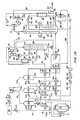
- a natural gas feed stream of high pressure 69 to 138 bar (1000 to 2000 psia) can be processed in the flow scheme shown in this drawing.
- a typical feed at 98.7 bar (1431 psia) consists of methane 93%, ethane 4%, propane 0.6%, butane 0.3%, isobutane 0.1%, nitrogen 0.8% wnd trace amounts of higher hydrocarbons and water.
- the feed stream in line 10 is initially cooled to -37°C (-34°F) through a series of cascade heat exchangers 14, 16 and 18 which are cooled by a closed circuit refrigerant system.
- the refrigerant is generally a single component hydrocarbon such as C 2 , C 3 or C 4 paraffin hydrocarbons.
- Propane is the preferred single component refrigerant used in this first closed cycle refrigeration system because of its refrigeration duty at the operational temperature and pressure and because it can be provided from the separated natural gas liquids for makeup.
- This closed circuit refrigeration system constitutes a high level refrigerant because it is at a relatively warm temperature for a process involving the liquefaction of natural gas. In light of its relatively warm temperature, high level refrigerant is relatively less expensive to use than lower level refrigerants.
- the precooled high pressure feed is introduced by way of line 20 into an expander turbine 44 where it is reduced in pressure to 50 bar (725 psia) at -67°C (-88°F) while producing mechanical energy.
- the expanded feed containing vapor and liquid in line 46 is introduced into the top of the scrub column 28.
- the feed to the top of the scrub column provides for sufficient fractionation of the methane-rich fraction from the heavier hydrocarbon fraction of the feedstock to provide makeup refrigerant.
- the scrub column 28 is operated at approximately 50 bar (725 psia).
- the heavier hydrocarbons are removed from the scrub column 28 in line 48 and a portion of the heavier hydrocarbons are recycled through reboiling heat exchanger 50 in order to provide reboil for the column.
- NGL natural gas liquids.
- the composition of the heavier hydrocarbons consist of 34.7% ethane, 17.8% propane, 13.5% butane, 4% isobutane, and residual amounts of pentane, isopentane and heptane.
- a methane-rich gas stream is removed as an overhead from the scrub column 28 in line 52.
- This overhead stream is at a temperature of -66°C (-87°F).
- the overhead stream is directed to a compressor 54 which is driven by the expander 44. In this manner, the energy derived from reducing the pressure of the feed stream is preserved and utilized for the compression of product stream from the scrub column 28.
- the overhead stream is compressed from a pressure of approximately 50 bar (725 psia) at the inlet of the compressor to a pressure of 77.6 bar (1037 psia) at the exit of the compressor 54. At this point the overhead stream in line 56 is also at a temperature of -44°C (-47°F).
- the methane-rich stream which can contain appreciably heavier hydrocarbons despite partial removal in the scrub column 28, is now introduced into the main heat exchanger 60 where it is cooled, liquefied and subcooled in order to be removed and stored or transported as LNG or liquid natural gas.
- the methane-rich stream is first cooled in bundle 62 of a coil wound heat exchanger 60 utilizing a multicomponent hydrocarbon refrigerant.
- This multicomponent hydrocarbon refrigerant constitues a second closed circuit refrigeration system which operates at a low level because it must be at a sufficiently low temperature to liquefy and subcool natural gas.
- Such low level refrigeration is expensive to use because it requires a considerable power input to maintain the refrigerant at the low temperature necessary for liquefaction, -157°C (-250°F).
- the stream is liquefied in this first bundle and is removed from the heat exchanger 60 to be expanded through valve 64 wherein the temperature of the stream is approximately -129°C (-200°F) and is reduced in pressure to 20.7 bar (300 psia).
- the liquid stream is then conducted through the second bundle 66 for further cooling against the multicomponent refrigerant wherein it exits the heat exchanger 60 in line 68 at approximately -157°C (-250°F) and 18.6 bar (270 psia).
- the stream is expanded through valve 70 in order to remove a small amount of vaporous methane in the phase separator 72 to provide plant fuel.
- Approximately 3% of the flow into vessel 72 is removed as plant fuel gas in line 80.
- the remaining stream is removed as product liquid from the bottom of vessel 72 and is pumped by pumping means 74 to storage 76.
- the product liquid natural gas can then be removed for export in line 78.
- Vapor phase methane which develops during storage of the natural gas product is removed and compressed by compressor 84 for inclusion as plant fuel.
- the main fuel stream in line 80 is warmed in heat exchanger 82 against multi- component refrigerant.
- the combined plant fuel from line 80 and pump 84 is compressed in compressor 88 and exported in line 90 to power utilization for the plant.
- the refrigerant for the liquefaction of the methane-rich stream consists of multiple hydrocarbon components, generally nitrogen, methane, ethane and propane.
- the specific multi- component refrigerant utilized in this embodiment comprises ethane 47%, methane 41%, propane 8.9% and nitrogen 2.9%.
- Makeup multiple component refrigerant may be introduced into the liquefaction refrigeration cycle through line 198 which is controlled by a valve.
- Makeup refrigerant and recycle refrigerant in line 196 are compressed in compressor 152 and aftercooled in a cold water heat exchanger 154. A second level of compression is produced by compressor 156 and again is followed by aftercooling with cold water heat exchanger 158.
- the multicomponent refrigerant is phase separated in vessel 170. Approximately 25% of the flow is removed as vapor in line 182 and the remaining 75% of the refrigerant flow is removed as liquid in line 172.
- the liquid refrigerant enters bundle tube circuit 176 of the main heat exchanger 60 and is cooled to -129°C (-200°F) before being removed from the heat exchanger and reduced in pressure through valve 178. The reduced pressure liquid is then sprayed upon the lower tier of bundles in the heat exchanger 60 through spray head 180.
- the vapor from the multicomponent refrigerant phase separator 170 is removed in line 182 and a slipstream is further removed from that stream in line 184.
- the bulk of the vapor phase refrigerant in line 182 is directed through line 188 into the warm end of the heat exchanger 60.
- the vaporized refrigerant is cooled and liquefied to .approximately -157°C (-250°F) in bundle tube circuit 190 before being removed and reduced in pressure through valve 192.
- the slipstream in line 184 is cooled and liquefied to a temperature of approximately -157°C (-250°F) by heat exchange with the product fuel for the plant in intercooling heat exchanger 82 before being reduced in pressure through valve 186 and joining the vapor stream liquefied in the main heat exchanger 60.
- the co-mingled streams are then sprayed over the internal bundle of the heat exchanger through spray heads 194.
- the refrigerants are then recycled by removal from the bottom of the heat exchanger 60 in line 196.
- This multicomponent refrigerant which is used to liquefy the natural gas is cooled itself by a combination of heat exchange with the initial single component refrigeration cycle and the reduction in pressure which occurs in the main heat exchanger 60.
- the heat exchange against the single component refrigerant occurs in a cascade series of exchanges as outlined above. This refrigeration cycle for the initial single component refrigerant will now be set forth.
- the single component refrigerant which is preferably propane, is compressed in a series of stages in compressor 92 to a pressure of approximately 13.8 bar (200 psia).
- the compressed single component refrigerant is then aftercooled and totally condensed in cold water heat exchangers 94 and 96 before being delivered to liquid reservoir 98.
- the liquid refrigerant is further sub-cooled in cold water heat exchanger 100 before being passed to refrigeration duty through line 102.
- the refrigerant is expanded through valve 104 and delivered to a supply-suction drum 108.
- the refrigerant in the vapor phase in drum 108 is removed for recompression in line 110.
- the liquid phase of the refrigerant in drum 108 is removed in line 118 and split into stream 120 which is split once again at line 122.
- the remaining stream in line 118 is expanded in valve. 126 before being introduced into supply-suction drum 128.
- the split stream in line 122 is heat exchanged against the feed in evaporative heat exchanger 14.
- the residual stream in line 120 is heat exchanged in evaporative heat exchanger 162 against the second refrigeration system containing multiple component refrigerant. This is the first of three cascade refrigerating heat exchanges between the initial single component refrigerant and the second multicomponent refrigerant, both cycles of which are closed and are heat exchanged only indirectly in these exchangers.
- the vaporized single component refrigerant now in line 124 is mixed with the vaporized single component refrigerant introduced in line 122 and returned to the first supply-suction drum 108 through line 116.
- the single component refrigerant in supply-suction drum 128 is separated into a vapor and liquid phase.
- the vapor phase is removed in line 130 for recompression in compressor 92.
- the liquid phase is removed in line 132 wherein the stream is split into line 134 and a residual stream which is expanded in valve 140 before being introduced into supply-suction drum 142.
- the liquid refrigerant stream in line 134 is further split into line 136 which cools the feed in the second cascade evaporative heat exchanger 16.
- the remaining stream in line 134 is used to cool the second refrigerant, consisting of a multi- component refrigerant, in the second of a series of three cascade evaporative heat exchangers, specifically in this case exchanger 164.
- the now vaporized single component refrigerant in line 138 is mixed with the now vaporized refrigerant introduced in line 136 and returned to supply-suction drum 128.
- the single component refrigerant delivered to supply-suction drum 142 through line 132 and valve 140 is also separated into a vapor phase and a liquid phase.
- the vapor phase is supplied to the compressor 92 for recompression through line 144.
- the liquid phase refrigerant is directed through line 146 for further heat exchange duty.
- a side stream 148 is removed wherein the refrigerant further cools the feed stream in the third cascade evaporative heat exchanger 18 while being vaporized.
- the residual single component refrigerant in line 146 cools the second refrigeration circuit containing a multi- component refrigerant in evaporative heat exchanger 166. In this manner, the ' single component refrigerant is used to cool the methane feed to the scrub column 28.
- the single component refrigerant is vaporized as it leaves exchangers 18 and 166 and the combined vapor streams are returned to supply-suction drum 142.
- the process circuit of the present invention has several advantages over the prior art as set forth in U.S. Patent 4,065,278.
- One of the most important advantages of the present invention is the reduction in the number of bundles in the main heat exchanger 60 from the three bundle configuration shown in the prior art patent including bundle 36 to a two bundle configuration as shown in Fig. 1A in heat exchanger 60 of the present application.
- Another advantage of the embodiment of Fig. 1A is that the entire feed is introduced into the column 28 at a point near the top of said column. This allows the single feed to supply all of the liquid reflux for the column.
- Fig. 1A is specifically adapted for processing feedstock where little if any heavy hydrocarbon removal is desired or such hydrocarbons do not exist.
- the alternate embodiment of the process of Fig. 1 A can be used in which additional processing advantages are realized. This alternate or second embodiment is shown in Fig. 1B.
- Fig. 1B shows the following preferred mode of operation.
- the process of Fig. 1 B can operate on medium pressure feeds 41.4 to 75.9 bar (600 to 1100 psia).
- a feed at 885 psia consists of methane 83%, ethane 10.5%, propane 3.7%, butane 1%, isobutane -0.65%, nitrogen 0.35% and trace amounts of higher hydrocarbons and water.
- Fig. 1B shows an initial separation of water from the feed in line 10, if this is necessary. Water separation is accomplished by cooling in heat exchanger 12 and then passage through a knock-out drum 11 and switching absorbent beds 13. Carbon dioxide can also be removed in such process treatment.
- Fig. 1B is specifically designed for heavy hydrocarbon removal and the feed stream to the scrub column differs markedly from Fig. 1A for this purpose.
- the feed natural gas is at a relatively medium pressure level, the feed may be phased separated several times before going to fractionation, which improves such fractionation processing.
- the feed in line 20 is introduced into a phase separator 22 wherein the liquid phase, constituting 18.5% of the feed, is removed as a bottom stream in line 26 and reduced in pressure in valve 24 from 59.3 to 36.6 bar (860 psi to 530 psi) before being introduced into a scrub column 28 as liquid feed at -53°C (-64°F).
- the vapor overhead from the vessel 22 is removed in line 30 wherein it is cooled in intercooling heat exchanger 32 to -54°C (-65°F) with the overhead from said scrub column 28.
- the further cooled overhead in line 34 is introduced into a second phase separator 36.
- the liquid phase constituting 16% of the stream 34, is removed as a bottom stream in line 38 and expanded in valve 40 before being introduced as a second liquid feed stream into the scrub column 28 at -73°C (-99°F).
- the vapor phase from the vessel 36 is introduced by way of line 42 into the expander turbine 44, where it is reduced in pressure while producing mechanical energy.
- the expanded feed containing vapor and liquid in line 46 is introduced into the top of the scrub column 28.
- the overhead, in line 52, is introduced into the intercooling heat exchanger 32 in order to precool a portion of the feed to the scrub column 28 and to recover a portion of the refrigeration value of the overhead stream.
- the overhead stream leaves the heat exchanger 32 at approximately -40°C (-40°F) and is directed to the compressor 54, which is driven by the expander 44.
- the compressed methane-rich stream is then cooled by heat exchange in evaporative heat exchanger 58 against the single component refrigerant of the first refrigeration circuit.
- the stream exits the heat exchanger 58 at -37°C (-35°F).
- the methane-rich stream from the exchanger 58 of Fig. 1 B is then cooled, liquefied and subcooled as in the scheme illustrated in Fig. 1A and discussed above.
- This second embodiment, Fig. 1 B also has the advantage of reducing the three bundle configuration of the prior art to a two bundle heat exchanger 60 with attendant cost savings.
- the second embodiment provides other advantages when NGL is being removed.
- the compressed overhead stream from the scrub column 28 in the present invention after intercooling and expansion, is cooled in a simple evaporative heat exchanger 58 against high level (relatively warm) single component refrigerant rather than the more expensive low level (relatively cold) multicomponent refrigerant which also required an expensive third bundle fabrication in the main heat exchanger of the prior art.
- Another advantage of the present invention shown in Fig. 1 B over the prior art is the heat exchange of the reflux feed to the scrub column against the methane-rich overhead stream from the column.
- Fig. 1A and 1B provide improved economic operation of a separation and liquefaction system for natural gas being converted to liquefied natural gas. Because of these improvements in the present invention over the process of the prior art, the present invention achieves an increase greater than 3% efficiency by reduced total compressor horse power requirements needed for operation for a similar capacity of production of LNG.
- the surface area of the main heat exchanger 60 of the present invention is reduced 41 % from the prior art, such as U.S. Patent 4,065,278.
- Such heat exchanger surface area is an important determination with respect to the cost of fabricating the apparatus for an LNG process. Therefore, with this surface area reduction, the present invention in the embodiment shown in Fig. 1 provides a main exchanger cost reduction of 47% over the stated prior art above.
- the second embodiment discussed above is appropriate for what is termed medium pressure feeds, such as 41.4 to 75.9 bar (600 to 1,100 psia).
- medium pressure feeds such as 41.4 to 75.9 bar (600 to 1,100 psia).
- natural gas streams are available at 69 to 138 bar (1,000 to 2,000 psia) and are referred to herein as high pressure streams, such as those designated to be processed the first embodiment of Fig. 1A. Because these streams are available at such pressures, it is beneficial to process the streams at those pressures rather than losing the inherent energy of the high pressure in order to process the stream through a medium pressure system. Therefore, a second version of the second embodiment of the present invention will now be described with reference to Fig.
- the system is specifically designed for a high pressure feed stream and NGL recovery, that is a stream at 69 to 138 bar (1,000 to 2,000 psia) and preferably a stream at 110.4 bar (1,600 psia) with heavy hydrocarbons which are to be recovered.
- a methane containing feedstock such as natural gas, is introduced into line 200 at a temperature of 8°C (46°F) and a pressure of 112 bar (1,624 psia).
- the stream flow is at a rate of 24,720 pound moles per hour consisting of 75% methane, 11.5% ethane, 8.5% propane, 2% butane, 1% isobutane and residual amounts of other C s to C 7 hydrocarbons.
- the feed stream in line 200 is initially cooled in a three step series of heat exchanges with a single component refrigerant in evaporative heat exchangers 202, 204 and 206. During this initial cooling, the feed stream is reduced in temperature to -37°C (-34°F).
- the cooled stream now in line 208, is further cooled in intercooling heat exchanger 210 against the overhead stream from the scrub column 216.
- the intercooling between streams reduces the feed stream to a temperature of -50°C (-59°F).
- the further cooled stream is then reduced in pressure by expanding the stream through an expander turbine 212 which further reduces the temperature to -70°C (-94°F) and reduces the pressure of the stream to 41.4 bar (600 psia).
- the feed stream is introduced into the scrub column 216 as its sole reflux stream.
- the column 216 operates at 41.4 bar (600 psia) and fractionates the methane-rich components of the feed stream from the heavier hydrocarbons, generally referred to as NGL or natural gas liquids.
- the NGL fraction is removed in line 218 wherein a portion of the NGL is recirculated by way of a heat exchanger 220.
- Approximately 21.4% of the feed to the column is removed in line 218, while 78.6% of the feed is removed as methane-rich product in line 222 as an overhead stream.
- the overhead stream as stated above, is passed through an intercooling heat exchanger where it is warmed in order to cool the feed to the column.
- the overhead stream after warming in exchanger 210 is at a temperature of -40°C (-40°F) in line 224.
- This methane-rich stream is then compressed in a compressor 226 which is mechanically joined to the expander 212 in order that the energy produced from expansion may be utilized efficiently in the recompression of the methane-rich gas stream.
- the compression of the methane-rich gas stream increases its temperature to -23°C (-10°F) and increases its pressure to 51.5 bar (747 psia).
- the methane-rich gas stream in line 228 is then cooled once more against the single component refrigerant in the first refrigeration cycle in evaporative heat exchanger 230 where the stream is reduced in temperature to -37°C (-34°F).
- the stream is then introduced into the main heat exchanger 232 wherein it will be cooled, liquefied and subcooled to form liquefied natural gas or LNG.
- the methane-rich stream in line 228 is introduced into the main heat exchanger 232 in the first stage bundle 234 wherein it is cooled and liquefied to -129°C (-200°F) against a second multicomponent refrigerant in a second and separate refrigeration cycle from that of the first single component refrigeration cycle.
- the liquefied stream is then reduced in pressure by passage through a valve which expands the stream to a pressure of 20.7 bar (300 psia) before the stream is introduced into the second heat exchanger bundle 236 wherein the methane-rich stream is subcooled against additional multi- component refrigerant and exits the man heat exchanger 232 at a temperature of -153°C (-244°F) and a pressure of 18.6 bar (270 psia).
- the subcooled stream is then reduced in pressure through an expander valve to a pressure of 18 psia and a temperature of -159°C (-255°F).
- a two phase stream is produced by this expansion and the phases are separated in phase separator vessel 238.
- a multicomponent refrigerant consisting of predominantly methane and ethane and lesser amounts of propane and nitrogen are used to liquefy the natural gas in the heat exchanger 232.
- This multicomponent refrigerant is recycled, but a portion of makeup refrigerant can be added just prior to the initial compression of the refrigerant in compressor 294.
- the refrigerant is aftercooled against cold water and further compressed in compressor 296 with subsequent aftercooling against cold water to arrive at a pressure of 42.2 bar (612 psia) at 18°C (55°F).
- the multicomponent refrigerant is heat exchanged against the single component refrigerant in line 298 in a series of cascade heat exchangers 260, 276 and 290 wherein the multicomponent refrigerant is partially liquefied and cooled to a temperature of -37°C (-34°F).
- the refrigerant is then phase separated in phase separator vessel 300, wherein 77% of the refrigerant is removed as a liquid stream in line 302 and 23% is removed in line 316 as a vapor phase.
- the liquid refrigerant enters main heat exchanger 232 in bundle tube circuit 306 wherein it is cooled to -129°C (-200°F) before a portion of the refrigerant is split out and the remaining refrigerant is expanded in a valve in line 308, after which the refrigerant is sprayed over the warm bundle (first stage) of the heat exchanger 232 from spray nozzles in line 308.
- the split stream is expanded and provides refrigeration to the stream in line 314 in heat exchanger 310. This provides refrigeration for the fractionation of NGL in downstream equipment not deemed to be a part of the present invention.
- the multicomponent refrigerant now in line 312 is further expanded and rejoins the recycling refrigerant from the base of the heat exchanger 232.
- a portion of the vaporous refrigerant from phase separator vessel 300 in line 318 is cooled through the entire course of the main heat exchanger 232, while the remaining portion of the vaporous refrigerant from the overhead of phase separator 300 in line 304 is cooled against vaporous LNG product in intercooling heat exchanger 242 before being expanded and rejoining the stream in line 318 to be introduced into the head of the exchanger 232 and sprayed on the cold bundle (second stage) of the main heat exchanger.
- the single component refrigerant which initially cools the feed stream and also supplies a portion of the cooling for the second multi- component refrigerant in evaporative heat exchangers 260, 276 and 290 is compressed in compressor 250 which consists of a three stage compressor.
- the single component refrigerant which is preferably propane, is now at a pressure of 8.97 bar (130 psia) and a temperature of 41°C (105°F).
- the refrigerant is aftercooled and totally condensed in a series of cold water heat exchangers and supplied to a reservoir tank 252. Refrigerant is removed from the tank 252 and further cooled in a cold water heat exchanger before being expanded and supplied to the suction-supply drum 254.
- Liquid refrigerant is removed from the bottom of the drum 254 in line 258, a portion of which is directed in line 266 to a second suction-supply drum 268.
- the remaining refrigerant in line 258 is again split in order that a portion of the refrigerant will be used to cool the feed stream 200 in evaporative heat exchanger 202 before being returned to the drum 254 in line 264 as vapor.
- the last portion of the refrigerant in line 258 is used to cool the second multi- component refrigerant in evaporative heat exchanger 260 before being returned in line 262 as vapor to be mixed with the vaporized refrigerant in line 264 and together returned to the drum 254. This vapor is then returned in line 256 for compression.
- a liquid propane refrigerant is removed from the base of drum 268 and is split into three streams, in which refrigerant in line 280 is supplied to a third suction-supply drum 282, a portion is utilized as a refrigerant in evaporative heat exchanger 204 and returned to drum 268 in line 278 while the remaining refrigerant in line 272 is directed in line 274 to further cool the second multicomponent refrigerant in evaporative heat exchanger 276 before the vapor is returned to line 278 and drum 268 to be collected and directed in line 270 for recompression.
- the refrigerant supplied in line 280 to suction-supply drum 282 is utilized in line 286 for refrigeration of the feed stream in evaporative heat exchanger 206 and also for refrigeration of the second, multi- component refrigerant in evaporative heat exchanger 290 and aftercooling of the separated methane-rich stream from the scrub column 216 in heat exchanger 230.
- the vaporized refrigerants from these heat exchangers are collected in line 292 and returned to drum 282 wherein the vapor is removed from the overhead of the drum and supplied through line 284 to the compressor for combined recompression with the other vapor streams from the other drums.
- This second high pressure version of the present invention provides improved production efficiencies over the prior art similar to the efficiencies calculated for the second embodiment shown in Fig. 1B and discussed above with respect to a medium pressure feed stream.
- the second version has the advantage of reduced capital costs with the reduction in the number of bundles in the main heat exchanger from the closest prior art, namely U.S. Patent 4,065,278.
- This second version also has reduced overall compressor horse power requirements in comparison to the medium pressure prior art processes when adjustment is made for the fact that this embodiment operates on a high pressure feed, whereas the closest prior art operates on medium pressure feeds.
- the system illustrated in Fig. 2 has a 3.3% efficiency over U.S. Patent 4,065,278.
- This reduction in horse power in conjunction with the reduction in capital costs of fabricating the main heat exchanger provides an attractive advantage of the present process over prior art processes for extracting NGL's and for liquefaction of natural gas streams.
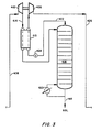
- FIG. 3 An alternate embodiment for performing the separation of a high pressure natural gas feed such as was demonstrated in Fig. 2 above, is shown in Fig. 3.
- the precooling with a single component refrigerant is the same as in the second embodiment illustrated in Fig. 2 as well as the liquefaction processing downstream of the separation in the main heat exchanger. Therefore, this alternate embodiment is shown only in the feed to the scrub column 316 where the process variation from Fig. 2 exists.
- the feed natural gas at high pressure is initially cooled against a single component refrigerant in three cascade evaporative heat exchangers as shown in Fig. 2.
- the precooled feed in line 408 is at a temperature of -37°C (-34°F) and a pressure of 110.4 bar (1,600 psia).
- the feed is reduced in pressure by expansion through an expander 412, wherein the temperature is further reduced to -65°C (-84°F) and the pressure is reduced to 41.4 bar (600 psia).
- the expanded stream is then cooled by heat exchange with the overhead from the scrub column in a directly opposite sequence from that flow scheme illustrated in Fig. 2.
- the expanded stream in line 414 is cooled to -67°C (-89°F) by heat exchange in the intercooling heat exchanger 410.
- the stream is then introduced into the scrub column 416 which operates at approximately 41.4 bar (600 psia). Heavier hydrocarbons such as ethane, propane, butane and other multiple hydrocarbons are removed as natural gas liquids (NGL) in line 418. A portion of the stream is removed for recirculation through reboiling heat exchanger 420.
- a methane-rich stream is withdrawn from the scrub column 416 in line 422 as an overhead fraction containing 95% methane with residual portions of ethane and lesser amounts of other heavier hydrocarbons.
- This stream 422 is reduced in pressure through valve 424 to 450 psia with an attendent reduction in temperature to -76°C (-105°F).
- the stream is warmed against the incoming feed to the column in the intercooling heat exchanger 410 and exits that exchanger at -69°C (-91°F).
- the methane-rich stream is then compressed in compressor 426, which utilizes the mechanical energy derived from expansion in the expander 412.
- the pressure of the overhead stream 422 is then elevated to 43.3 bar (627 psia) by this compression before being sent to the main heat exchanger for cooling, liquefaction and subcooling to liquefied natural gas, LNG as described in Fig. 2 above.
- This alternate embodiment shown in Fig. 3 achieves similar efficiencies for the separation of NGL's and the liquefaction of natural gas when compared against the prior art, such as U.S. Patent 4,065,278.
- This embodiment utilizes the same two bundle liquefying heat exchanger with its attendant reduction in capital costs as described above.
- the Fig. 3 cycle also achieves greater cooling of the methane-rich stream coming from the overhead of the scrub column and therefore does not need the evaporative heat exchanger 230 shown in Fig. 2. Therefore with this greater reduction in temperature of the methane-rich stream in the embodiment shown in Fig. 3, capital costs may be saved over that flowpath shown in Fig. 2.
- This change in conjunction with the alteration in sequence of intercooling and expansion of the feed to the scrub column are the only distinctions between these two high pressure feed versions of the present invention as illustrated in Fig. 2 and Fig. 3.
- the improved high pressure cycle shown in Figs. 2 and 3 incorporate the same refrigeration recovery device consisting of an intercooling heat exchanger as shown in the medium pressure cycle of Fig. 1B.
- This refrigeration recovery is used to either further cool the expander outlet, Fig. 3, or to precool the expander inlet, Fig. 2.
- the scrub column overhead 422 When it is used to cool the expander outlet, the scrub column overhead 422 must be reduced in pressure to provide a lower temperature and positive cold end temperature difference for the refrigeration recovery in heat exchanger 410.
- the column overhead precools the expander inlet, Fig.
- the resulting compressor outlet temperature in line 228 is somewhat warmer and thus the additional evaporative heat exchanger is used to recool the methane-rich feed to -37°C (-34°F) prior to introduction into the main heat exchanger for liquefaction.
- This evaporative heat exchanger 230 was not required in the system of Fig. 3 since the compressor outlet stream in line 428 was cooled to -45°C (-49°F), well below the lowest single component refrigerant temperature.
- the scrub column may be designed to recover only sufficient C 2 and C 3 for refrigerant makeup. Heavy hydrocarbons such as benzene may also have to be removed to prevent freeze-up in the main exchanger. Both refrigerant recovery and heavies removal impose less load on the scrub column. Consequently, the scrub column may be operated at a higher pressure and temperature than required for NGL recovery. As less heavies need to be recovered, the scrub column may be operated at higher pressures resulting in the scrub column overhead being recompressed and returned to the main exchanger at higher pressure for liquefaction.
- the present invention eliminates the need for low level refrigeration from the low level refrigeration circuit for cooling of the column feed and reduces the main heat exchanger cost by eliminating a tubing bundle. This is accomplished by expanding the high level refrigerant precooled feed and delivering it directly to the top of the scrub column to provide all of the liquid or reflux necessary in the column for the desired amount of separation of heavy hydrocarbons from methane in methane-containing feed streams.
- the expansion is energy efficient because the energy provided by the expansion is recovered in the compressor which recompresses the methane-rich overhead for efficient liquefaction of the methane against low level refrigeration. It is contemplated that any of the methane liquefaction processes set forth in the patents identified above should benefit and be more energy efficient with the improvement constituting the present invention.
Landscapes
- Engineering & Computer Science (AREA)
- General Engineering & Computer Science (AREA)
- Physics & Mathematics (AREA)
- Mechanical Engineering (AREA)
- Thermal Sciences (AREA)
- Oil, Petroleum & Natural Gas (AREA)
- Chemical & Material Sciences (AREA)
- Chemical Kinetics & Catalysis (AREA)
- General Chemical & Material Sciences (AREA)
- Separation By Low-Temperature Treatments (AREA)
- Medicines Containing Plant Substances (AREA)
- Tea And Coffee (AREA)
- Fats And Perfumes (AREA)
Applications Claiming Priority (2)
| Application Number | Priority Date | Filing Date | Title |
|---|---|---|---|
| US412686 | 1982-08-30 | ||
| US06/412,686 US4445916A (en) | 1982-08-30 | 1982-08-30 | Process for liquefying methane |
Publications (3)
| Publication Number | Publication Date |
|---|---|
| EP0102087A2 EP0102087A2 (en) | 1984-03-07 |
| EP0102087A3 EP0102087A3 (en) | 1985-01-16 |
| EP0102087B1 true EP0102087B1 (en) | 1986-12-30 |
Family
ID=23634028
Family Applications (1)
| Application Number | Title | Priority Date | Filing Date |
|---|---|---|---|
| EP83108546A Expired EP0102087B1 (en) | 1982-08-30 | 1983-08-30 | Process for liquefying methane |
Country Status (11)
| Country | Link |
|---|---|
| US (1) | US4445916A (cg-RX-API-DMAC10.html) |
| EP (1) | EP0102087B1 (cg-RX-API-DMAC10.html) |
| JP (1) | JPS5981483A (cg-RX-API-DMAC10.html) |
| AR (1) | AR231349A1 (cg-RX-API-DMAC10.html) |
| AU (1) | AU553598B2 (cg-RX-API-DMAC10.html) |
| CA (1) | CA1200191A (cg-RX-API-DMAC10.html) |
| DE (1) | DE3368758D1 (cg-RX-API-DMAC10.html) |
| ES (1) | ES525205A0 (cg-RX-API-DMAC10.html) |
| MX (1) | MX163352A (cg-RX-API-DMAC10.html) |
| MY (1) | MY101002A (cg-RX-API-DMAC10.html) |
| NO (1) | NO160600C (cg-RX-API-DMAC10.html) |
Cited By (4)
| Publication number | Priority date | Publication date | Assignee | Title |
|---|---|---|---|---|
| WO2004065869A1 (en) * | 2003-01-22 | 2004-08-05 | Lng International Pty Ltd | A refrigeration process and the production of liquefied natural gas |
| US7375973B2 (en) | 2000-12-29 | 2008-05-20 | Vertu Limited | Casing for a communication device |
| US7693557B2 (en) | 2000-12-29 | 2010-04-06 | Nokia Corporation | Method of producing a telephone device |
| US7830671B2 (en) | 2000-12-29 | 2010-11-09 | Vertu Limited | Casing |
Families Citing this family (73)
| Publication number | Priority date | Publication date | Assignee | Title |
|---|---|---|---|---|
| DE3531307A1 (de) * | 1985-09-02 | 1987-03-05 | Linde Ag | Verfahren zur abtrennung von c(pfeil abwaerts)2(pfeil abwaerts)(pfeil abwaerts)+(pfeil abwaerts)-kohlenwasserstoffen aus erdgas |
| US4970867A (en) * | 1989-08-21 | 1990-11-20 | Air Products And Chemicals, Inc. | Liquefaction of natural gas using process-loaded expanders |
| US5325673A (en) * | 1993-02-23 | 1994-07-05 | The M. W. Kellogg Company | Natural gas liquefaction pretreatment process |
| FR2714722B1 (fr) * | 1993-12-30 | 1997-11-21 | Inst Francais Du Petrole | Procédé et appareil de liquéfaction d'un gaz naturel. |
| DE69523437T2 (de) * | 1994-12-09 | 2002-06-20 | Kabushiki Kaisha Kobe Seiko Sho (Kobe Steel, Ltd.) | Anlage und Verfahren zur Gasverflüssigung |
| WO1997036139A1 (en) * | 1996-03-26 | 1997-10-02 | Phillips Petroleum Company | Aromatics and/or heavies removal from a methane-based feed by condensation and stripping |
| US5755114A (en) * | 1997-01-06 | 1998-05-26 | Abb Randall Corporation | Use of a turboexpander cycle in liquefied natural gas process |
| TW366411B (en) * | 1997-06-20 | 1999-08-11 | Exxon Production Research Co | Improved process for liquefaction of natural gas |
| TW368596B (en) * | 1997-06-20 | 1999-09-01 | Exxon Production Research Co | Improved multi-component refrigeration process for liquefaction of natural gas |
| DZ2534A1 (fr) * | 1997-06-20 | 2003-02-08 | Exxon Production Research Co | Procédé perfectionné de réfrigération en cascade pour la liquéfaction du gaz naturel. |
| TW366409B (en) * | 1997-07-01 | 1999-08-11 | Exxon Production Research Co | Process for liquefying a natural gas stream containing at least one freezable component |
| FR2772896B1 (fr) * | 1997-12-22 | 2000-01-28 | Inst Francais Du Petrole | Procede de liquefaction d'un gaz notamment un gaz naturel ou air comportant une purge a moyenne pression et son application |
| GB9911021D0 (en) * | 1999-05-13 | 1999-07-14 | Kvaerner Oil & Gas As | Process for treating and liquefying gaseous mixtures as natural gases |
| US6347532B1 (en) | 1999-10-12 | 2002-02-19 | Air Products And Chemicals, Inc. | Gas liquefaction process with partial condensation of mixed refrigerant at intermediate temperatures |
| US6401486B1 (en) | 2000-05-18 | 2002-06-11 | Rong-Jwyn Lee | Enhanced NGL recovery utilizing refrigeration and reflux from LNG plants |
| US6367286B1 (en) * | 2000-11-01 | 2002-04-09 | Black & Veatch Pritchard, Inc. | System and process for liquefying high pressure natural gas |
| US6526777B1 (en) * | 2001-04-20 | 2003-03-04 | Elcor Corporation | LNG production in cryogenic natural gas processing plants |
| US6742358B2 (en) * | 2001-06-08 | 2004-06-01 | Elkcorp | Natural gas liquefaction |
| UA76750C2 (uk) * | 2001-06-08 | 2006-09-15 | Елккорп | Спосіб зрідження природного газу (варіанти) |
| MXPA03011495A (es) * | 2001-06-29 | 2004-03-19 | Exxonmobil Upstream Res Co | Proceso para recuperar etano e hidrocarburos mas pesados de una mezcla liquida presurizada rica en metano. |
| US7078008B2 (en) * | 2002-10-01 | 2006-07-18 | Conocophillips Company | Process for converting alkanes to carbon filaments |
| US6658890B1 (en) * | 2002-11-13 | 2003-12-09 | Conocophillips Company | Enhanced methane flash system for natural gas liquefaction |
| US6662589B1 (en) | 2003-04-16 | 2003-12-16 | Air Products And Chemicals, Inc. | Integrated high pressure NGL recovery in the production of liquefied natural gas |
| US6925837B2 (en) * | 2003-10-28 | 2005-08-09 | Conocophillips Company | Enhanced operation of LNG facility equipped with refluxed heavies removal column |
| JP4447639B2 (ja) * | 2004-07-01 | 2010-04-07 | オートロフ・エンジニアーズ・リミテッド | 液化天然ガスの処理 |
| EP1792130B1 (en) * | 2004-08-06 | 2017-04-05 | BP Corporation North America Inc. | Natural gas liquefaction process |
| US7607310B2 (en) * | 2004-08-26 | 2009-10-27 | Seaone Maritime Corp. | Storage of natural gas in liquid solvents and methods to absorb and segregate natural gas into and out of liquid solvents |
| KR20070111531A (ko) * | 2005-02-17 | 2007-11-21 | 쉘 인터내셔날 리써취 마트샤피지 비.브이. | 천연 가스 액화 설비 및 액화 방법 |
| MY142263A (en) * | 2005-04-12 | 2010-11-15 | Shell Int Research | Method and apparatus for liquefying a natural gas stream |
| US20070157663A1 (en) * | 2005-07-07 | 2007-07-12 | Fluor Technologies Corporation | Configurations and methods of integrated NGL recovery and LNG liquefaction |
| DE102006021620B4 (de) | 2006-05-09 | 2019-04-11 | Linde Ag | Vorbehandlung eines zu verflüssigenden Erdgasstromes |
| MX2008013462A (es) * | 2006-06-02 | 2008-10-29 | Ortloff Engineers Ltd | Procesamiento de gas natural licuado. |
| US20080016910A1 (en) * | 2006-07-21 | 2008-01-24 | Adam Adrian Brostow | Integrated NGL recovery in the production of liquefied natural gas |
| AU2007285734B2 (en) * | 2006-08-17 | 2010-07-08 | Shell Internationale Research Maatschappij B.V. | Method and apparatus for liquefying a hydrocarbon-containing feed stream |
| RU2443952C2 (ru) * | 2006-09-22 | 2012-02-27 | Шелл Интернэшнл Рисерч Маатсхаппий Б.В. | Способ и устройство для сжижения потока углеводородов |
| JP4942451B2 (ja) * | 2006-10-25 | 2012-05-30 | 東芝テック株式会社 | セルフチェックアウト端末 |
| DE102007007097A1 (de) * | 2007-02-13 | 2008-08-14 | Linde Ag | Verfahren zum Verflüssigen eines Kohlenwasserstoff-reichen Stromes |
| DE102007010032A1 (de) * | 2007-03-01 | 2008-09-04 | Linde Ag | Verfahren zum Abtrennen von Stickstoff aus verflüssigtem Erdgas |
| US9869510B2 (en) * | 2007-05-17 | 2018-01-16 | Ortloff Engineers, Ltd. | Liquefied natural gas processing |
| NO329177B1 (no) * | 2007-06-22 | 2010-09-06 | Kanfa Aragon As | Fremgangsmåte og system til dannelse av flytende LNG |
| US8020406B2 (en) | 2007-11-05 | 2011-09-20 | David Vandor | Method and system for the small-scale production of liquified natural gas (LNG) from low-pressure gas |
| BRPI0820028B1 (pt) * | 2007-12-10 | 2020-09-24 | Conocophillips Company | Processo para liquefazer uma corrente de gás natural |
| US20090151391A1 (en) * | 2007-12-12 | 2009-06-18 | Conocophillips Company | Lng facility employing a heavies enriching stream |
| US8534094B2 (en) * | 2008-04-09 | 2013-09-17 | Shell Oil Company | Method and apparatus for liquefying a hydrocarbon stream |
| US20090282865A1 (en) | 2008-05-16 | 2009-11-19 | Ortloff Engineers, Ltd. | Liquefied Natural Gas and Hydrocarbon Gas Processing |
| US20100147024A1 (en) * | 2008-12-12 | 2010-06-17 | Air Products And Chemicals, Inc. | Alternative pre-cooling arrangement |
| US20100287982A1 (en) | 2009-05-15 | 2010-11-18 | Ortloff Engineers, Ltd. | Liquefied Natural Gas and Hydrocarbon Gas Processing |
| US8434325B2 (en) | 2009-05-15 | 2013-05-07 | Ortloff Engineers, Ltd. | Liquefied natural gas and hydrocarbon gas processing |
| WO2012001001A2 (en) * | 2010-06-30 | 2012-01-05 | Shell Internationale Research Maatschappij B.V. | Method of treating a hydrocarbon stream comprising methane, and an apparatus therefor |
| AP2014007424A0 (en) | 2011-08-10 | 2014-02-28 | Conocophillips Co | Liquefied natural gas plant with ethylene independent heavies recovery system |
| JP2015506454A (ja) * | 2011-12-20 | 2015-03-02 | コノコフィリップス カンパニー | 動き環境下での天然ガスの液化 |
| EP2642228A1 (en) * | 2012-03-20 | 2013-09-25 | Shell Internationale Research Maatschappij B.V. | Method of preparing a cooled hydrocarbon stream and an apparatus therefor. |
| JP6225049B2 (ja) * | 2013-12-26 | 2017-11-01 | 千代田化工建設株式会社 | 天然ガスの液化システム及び液化方法 |
| JP6517251B2 (ja) * | 2013-12-26 | 2019-05-22 | 千代田化工建設株式会社 | 天然ガスの液化システム及び液化方法 |
| US20160061517A1 (en) * | 2014-08-29 | 2016-03-03 | Black & Veatch Holding Company | Dual mixed refrigerant system |
| DE102015002443A1 (de) * | 2015-02-26 | 2016-09-01 | Linde Aktiengesellschaft | Verfahren zum Verflüssigen von Erdgas |
| TWI707115B (zh) | 2015-04-10 | 2020-10-11 | 美商圖表能源與化學有限公司 | 混合製冷劑液化系統和方法 |
| US10619918B2 (en) | 2015-04-10 | 2020-04-14 | Chart Energy & Chemicals, Inc. | System and method for removing freezing components from a feed gas |
| AR105277A1 (es) | 2015-07-08 | 2017-09-20 | Chart Energy & Chemicals Inc | Sistema y método de refrigeración mixta |
| FR3039080B1 (fr) * | 2015-07-23 | 2019-05-17 | L'air Liquide, Societe Anonyme Pour L'etude Et L'exploitation Des Procedes Georges Claude | Methode de purification d'un gaz riche en hydrocarbures |
| US10551119B2 (en) | 2016-08-26 | 2020-02-04 | Ortloff Engineers, Ltd. | Hydrocarbon gas processing |
| US10551118B2 (en) | 2016-08-26 | 2020-02-04 | Ortloff Engineers, Ltd. | Hydrocarbon gas processing |
| US10533794B2 (en) | 2016-08-26 | 2020-01-14 | Ortloff Engineers, Ltd. | Hydrocarbon gas processing |
| CN106871576B (zh) * | 2017-01-25 | 2019-08-09 | 北京三泰天洁气体净化技术有限公司 | 工业合成气低温前脱甲烷方法及系统 |
| CN106679332A (zh) * | 2017-02-17 | 2017-05-17 | 查都(上海)科技有限公司 | 一种提高甲烷深冷分离lng收率的系统 |
| US11543180B2 (en) | 2017-06-01 | 2023-01-03 | Uop Llc | Hydrocarbon gas processing |
| US11428465B2 (en) | 2017-06-01 | 2022-08-30 | Uop Llc | Hydrocarbon gas processing |
| FR3086373B1 (fr) * | 2018-09-20 | 2020-12-11 | Air Liquide | Installation et procede d'epuration et de liquefaction de gaz naturel |
| EP3980483A4 (en) * | 2019-06-05 | 2023-06-21 | ConocoPhillips Company | TWO-STAGE HEAVY COMPONENTS REMOVAL IN LNG PROCESSING |
| JP7246285B2 (ja) * | 2019-08-28 | 2023-03-27 | 東洋エンジニアリング株式会社 | リーンlngの処理方法及び装置 |
| TW202309456A (zh) | 2021-05-14 | 2023-03-01 | 美商圖表能源與化學有限公司 | 側抽回流重烴去除系統和方法 |
| WO2023288162A1 (en) | 2021-07-16 | 2023-01-19 | Exxonmobil Upstream Research Company | Methods for operating hydrocarbon removal systems from natural gas streams |
| JP2024136765A (ja) * | 2023-03-24 | 2024-10-04 | エア・ウォーター株式会社 | 液化メタンの製造方法および液化メタンの製造装置 |
Family Cites Families (7)
| Publication number | Priority date | Publication date | Assignee | Title |
|---|---|---|---|---|
| US3292380A (en) * | 1964-04-28 | 1966-12-20 | Coastal States Gas Producing C | Method and equipment for treating hydrocarbon gases for pressure reduction and condensate recovery |
| US4004430A (en) * | 1974-09-30 | 1977-01-25 | The Lummus Company | Process and apparatus for treating natural gas |
| CA1021254A (en) * | 1974-10-22 | 1977-11-22 | Ortloff Corporation (The) | Natural gas processing |
| US4065278A (en) * | 1976-04-02 | 1977-12-27 | Air Products And Chemicals, Inc. | Process for manufacturing liquefied methane |
| JPS5472203A (en) * | 1977-11-21 | 1979-06-09 | Air Prod & Chem | Production of liquefied methane |
| US4203741A (en) * | 1978-06-14 | 1980-05-20 | Phillips Petroleum Company | Separate feed entry to separator-contactor in gas separation |
| US4225687A (en) * | 1979-07-23 | 1980-09-30 | General Electric Company | Novel halobisphenolethylene polycarbonate-polyetheramide-imide blends |
-
1982
- 1982-08-30 US US06/412,686 patent/US4445916A/en not_active Expired - Lifetime
-
1983
- 1983-08-23 CA CA000435183A patent/CA1200191A/en not_active Expired
- 1983-08-29 AR AR294035A patent/AR231349A1/es active
- 1983-08-29 NO NO833100A patent/NO160600C/no not_active IP Right Cessation
- 1983-08-29 ES ES525205A patent/ES525205A0/es active Granted
- 1983-08-30 MX MX198542A patent/MX163352A/es unknown
- 1983-08-30 DE DE8383108546T patent/DE3368758D1/de not_active Expired
- 1983-08-30 EP EP83108546A patent/EP0102087B1/en not_active Expired
- 1983-08-30 JP JP58158934A patent/JPS5981483A/ja active Granted
- 1983-09-05 AU AU18692/83A patent/AU553598B2/en not_active Ceased
-
1987
- 1987-07-29 MY MYPI87001173A patent/MY101002A/en unknown
Cited By (4)
| Publication number | Priority date | Publication date | Assignee | Title |
|---|---|---|---|---|
| US7375973B2 (en) | 2000-12-29 | 2008-05-20 | Vertu Limited | Casing for a communication device |
| US7693557B2 (en) | 2000-12-29 | 2010-04-06 | Nokia Corporation | Method of producing a telephone device |
| US7830671B2 (en) | 2000-12-29 | 2010-11-09 | Vertu Limited | Casing |
| WO2004065869A1 (en) * | 2003-01-22 | 2004-08-05 | Lng International Pty Ltd | A refrigeration process and the production of liquefied natural gas |
Also Published As
| Publication number | Publication date |
|---|---|
| AU1869283A (en) | 1984-03-08 |
| MX163352A (es) | 1992-04-28 |
| AU553598B2 (en) | 1986-07-24 |
| MY101002A (en) | 1991-06-29 |
| ES8507441A1 (es) | 1985-09-01 |
| NO160600C (no) | 1989-05-03 |
| AR231349A1 (es) | 1984-10-31 |
| EP0102087A2 (en) | 1984-03-07 |
| EP0102087A3 (en) | 1985-01-16 |
| US4445916A (en) | 1984-05-01 |
| DE3368758D1 (en) | 1987-02-05 |
| JPH049987B2 (cg-RX-API-DMAC10.html) | 1992-02-21 |
| CA1200191A (en) | 1986-02-04 |
| ES525205A0 (es) | 1985-09-01 |
| JPS5981483A (ja) | 1984-05-11 |
| NO160600B (no) | 1989-01-23 |
| NO833100L (no) | 1984-03-01 |
Similar Documents
| Publication | Publication Date | Title |
|---|---|---|
| EP0102087B1 (en) | Process for liquefying methane | |
| AU2002210701B2 (en) | A system and process for liquefying high pressure natural gas | |
| EP0143267B1 (en) | Dual mixed refrigerant natural gas liquefaction | |
| CA2291415C (en) | Dual mixed refrigerant cycle for gas liquefaction | |
| US6526777B1 (en) | LNG production in cryogenic natural gas processing plants | |
| EP0414107B1 (en) | Liquefaction of natural gas using process-loaded expanders | |
| US5755114A (en) | Use of a turboexpander cycle in liquefied natural gas process | |
| EP2564139B1 (en) | Process and apparatus for the liquefaction of natural gas | |
| AU2009235461B2 (en) | Method and apparatus for liquefying a hydrocarbon stream | |
| US20100175423A1 (en) | Methods and apparatus for liquefaction of natural gas and products therefrom | |
| US20130061632A1 (en) | Integrated NGL Recovery In the Production Of Liquefied Natural Gas | |
| KR20020066331A (ko) | 팽창 냉각에 의한 천연 가스의 액화방법 | |
| AU2002307315A1 (en) | LNG production in cryogenic natural gas processing plants | |
| AU2002210701A1 (en) | A system and process for liquefying high pressure natural gas | |
| EP1490639A1 (en) | Process for producing a pressurized liquefied gas product | |
| MX2007015604A (es) | Configuraciones y metodos integrados de recuperacion de liquidos de gas natural y de licuefaccion de gas natural licuado. | |
| WO1998059205A2 (en) | Improved process for liquefaction of natural gas | |
| EP0993585A1 (en) | Process for liquefying a natural gas stream containing at least one freezable component |
Legal Events
| Date | Code | Title | Description |
|---|---|---|---|
| PUAI | Public reference made under article 153(3) epc to a published international application that has entered the european phase |
Free format text: ORIGINAL CODE: 0009012 |
|
| AK | Designated contracting states |
Designated state(s): BE DE FR GB IT NL SE |
|
| PUAL | Search report despatched |
Free format text: ORIGINAL CODE: 0009013 |
|
| AK | Designated contracting states |
Designated state(s): BE DE FR GB IT NL SE |
|
| 17P | Request for examination filed |
Effective date: 19850412 |
|
| GRAA | (expected) grant |
Free format text: ORIGINAL CODE: 0009210 |
|
| ITF | It: translation for a ep patent filed | ||
| AK | Designated contracting states |
Kind code of ref document: B1 Designated state(s): BE DE FR GB IT NL SE |
|
| REF | Corresponds to: |
Ref document number: 3368758 Country of ref document: DE Date of ref document: 19870205 |
|
| ET | Fr: translation filed | ||
| PLBE | No opposition filed within time limit |
Free format text: ORIGINAL CODE: 0009261 |
|
| STAA | Information on the status of an ep patent application or granted ep patent |
Free format text: STATUS: NO OPPOSITION FILED WITHIN TIME LIMIT |
|
| 26N | No opposition filed | ||
| PG25 | Lapsed in a contracting state [announced via postgrant information from national office to epo] |
Ref country code: SE Effective date: 19880831 |
|
| ITTA | It: last paid annual fee | ||
| EUG | Se: european patent has lapsed |
Ref document number: 83108546.9 Effective date: 19890510 |
|
| PGFP | Annual fee paid to national office [announced via postgrant information from national office to epo] |
Ref country code: BE Payment date: 20000915 Year of fee payment: 18 |
|
| PG25 | Lapsed in a contracting state [announced via postgrant information from national office to epo] |
Ref country code: BE Free format text: LAPSE BECAUSE OF NON-PAYMENT OF DUE FEES Effective date: 20010831 |
|
| REG | Reference to a national code |
Ref country code: GB Ref legal event code: IF02 |
|
| BERE | Be: lapsed |
Owner name: AIR PRODUCTS AND CHEMICALS INC. Effective date: 20010831 |
|
| PGFP | Annual fee paid to national office [announced via postgrant information from national office to epo] |
Ref country code: NL Payment date: 20020618 Year of fee payment: 20 |
|
| PGFP | Annual fee paid to national office [announced via postgrant information from national office to epo] |
Ref country code: GB Payment date: 20020626 Year of fee payment: 20 |
|
| PGFP | Annual fee paid to national office [announced via postgrant information from national office to epo] |
Ref country code: FR Payment date: 20020805 Year of fee payment: 20 |
|
| PGFP | Annual fee paid to national office [announced via postgrant information from national office to epo] |
Ref country code: DE Payment date: 20020830 Year of fee payment: 20 |
|
| PG25 | Lapsed in a contracting state [announced via postgrant information from national office to epo] |
Ref country code: GB Free format text: LAPSE BECAUSE OF EXPIRATION OF PROTECTION Effective date: 20030829 |
|
| PG25 | Lapsed in a contracting state [announced via postgrant information from national office to epo] |
Ref country code: NL Free format text: LAPSE BECAUSE OF EXPIRATION OF PROTECTION Effective date: 20030830 |
|
| REG | Reference to a national code |
Ref country code: GB Ref legal event code: PE20 |
|
| NLV7 | Nl: ceased due to reaching the maximum lifetime of a patent |
Effective date: 20030830 |