EP0102011A2 - Fireplace-heater with recovery of heat from the combustion gases - Google Patents
Fireplace-heater with recovery of heat from the combustion gases Download PDFInfo
- Publication number
- EP0102011A2 EP0102011A2 EP83107979A EP83107979A EP0102011A2 EP 0102011 A2 EP0102011 A2 EP 0102011A2 EP 83107979 A EP83107979 A EP 83107979A EP 83107979 A EP83107979 A EP 83107979A EP 0102011 A2 EP0102011 A2 EP 0102011A2
- Authority
- EP
- European Patent Office
- Prior art keywords
- chamber
- fireplace
- heater according
- hearth
- ambient
- Prior art date
- Legal status (The legal status is an assumption and is not a legal conclusion. Google has not performed a legal analysis and makes no representation as to the accuracy of the status listed.)
- Granted
Links
- 238000011084 recovery Methods 0.000 title claims abstract description 5
- 239000000567 combustion gas Substances 0.000 title 1
- 239000003546 flue gas Substances 0.000 claims abstract description 30
- 239000012080 ambient air Substances 0.000 claims abstract description 16
- UGFAIRIUMAVXCW-UHFFFAOYSA-N Carbon monoxide Chemical compound [O+]#[C-] UGFAIRIUMAVXCW-UHFFFAOYSA-N 0.000 claims abstract description 12
- 239000003570 air Substances 0.000 claims abstract description 12
- 239000000779 smoke Substances 0.000 claims description 4
- 230000000694 effects Effects 0.000 claims description 2
- 230000002093 peripheral effect Effects 0.000 claims description 2
- 238000002485 combustion reaction Methods 0.000 description 6
- 238000005192 partition Methods 0.000 description 3
- 229910001018 Cast iron Inorganic materials 0.000 description 2
- 239000011521 glass Substances 0.000 description 2
- 238000009423 ventilation Methods 0.000 description 2
- 239000000919 ceramic Substances 0.000 description 1
- 239000004020 conductor Substances 0.000 description 1
- 238000010586 diagram Methods 0.000 description 1
- 239000007789 gas Substances 0.000 description 1
- 239000002184 metal Substances 0.000 description 1
- 229910052751 metal Inorganic materials 0.000 description 1
- 239000007769 metal material Substances 0.000 description 1
- 238000012986 modification Methods 0.000 description 1
- 230000004048 modification Effects 0.000 description 1
- 238000000926 separation method Methods 0.000 description 1
Images

Classifications
-
- F—MECHANICAL ENGINEERING; LIGHTING; HEATING; WEAPONS; BLASTING
- F24—HEATING; RANGES; VENTILATING
- F24B—DOMESTIC STOVES OR RANGES FOR SOLID FUELS; IMPLEMENTS FOR USE IN CONNECTION WITH STOVES OR RANGES
- F24B7/00—Stoves, ranges or flue-gas ducts, with additional provisions for convection heating
- F24B7/02—Stoves, ranges or flue-gas ducts, with additional provisions for convection heating with external air ducts
-
- F—MECHANICAL ENGINEERING; LIGHTING; HEATING; WEAPONS; BLASTING
- F24—HEATING; RANGES; VENTILATING
- F24B—DOMESTIC STOVES OR RANGES FOR SOLID FUELS; IMPLEMENTS FOR USE IN CONNECTION WITH STOVES OR RANGES
- F24B5/00—Combustion-air or flue-gas circulation in or around stoves or ranges
- F24B5/02—Combustion-air or flue-gas circulation in or around stoves or ranges in or around stoves
-
- F—MECHANICAL ENGINEERING; LIGHTING; HEATING; WEAPONS; BLASTING
- F24—HEATING; RANGES; VENTILATING
- F24H—FLUID HEATERS, e.g. WATER OR AIR HEATERS, HAVING HEAT-GENERATING MEANS, e.g. HEAT PUMPS, IN GENERAL
- F24H3/00—Air heaters
- F24H3/02—Air heaters with forced circulation
- F24H3/06—Air heaters with forced circulation the air being kept separate from the heating medium, e.g. using forced circulation of air over radiators
- F24H3/067—Air heaters with forced circulation the air being kept separate from the heating medium, e.g. using forced circulation of air over radiators using solid fuel
Definitions
- This invention relates to a fireplace-heater with full recovery of hot air.
- a consequent important object is to provide a structure wherein the flue gases, prior to being exhausted, are obliged to follow definite paths through exchange chambers.
- a further object is that of providing a simple modular structure which can fit fireplaces with different outward shapes.
- a fireplace-heater with full recovery of hot air comprising a hearth and at least one smoke chamber, characterized in that it has a plurality of smoke chambers serially arranged on the exterior of said hearth, said chambers being in turn enclosed in an outer ambient air circulation chamber for recovering heat from the flue gases by thermal exchange at wall members, a means being also provided to force said circulation of ambient air.
- a space heater comprises an outer enclosing body of glazed ceramic, indicated at 1 and enclosing a metal structure, specifically a cast iron one, which comprises a brazier 2 closed at the front by a door 3 having a glass window 31 and being fed with combustion air through a slotted grid 4 located on the front wall of the outer body 1, under the door 3 and above an ash collecting tray 5.
- Said brazier forms the bottom portion of a combustion chamber or hearth 6 defined laterally by first vertical sidewalls 7 and at the top by a substantially horizontal ceiling 8.
- Said first walls 7 extend at the bottom from the brazier 2 but end short of the ceiling 8 to leave a top side opening 49 for the passage of the flue gases.
- the ceiling 8 is connected laterally to second vertical walls 9 arranged parallel outside of the walls 7 and forming therewith a first chamber 50 swept by flue gases in a downward direction, as shown by the arrow 10. Additional sidewalls 15, located outside of the walls 9, form with the latter a second chamber 51 swept by flue gases in an upward direction, as shown by the arrow 11. If desired, to reverse the flue gas flow direction, there may be provided a baffle 12 located at a distance away from the bottom edges of the walls 9 so as to create a bottom side opening 52 and force the flue gases to reverse their direction as shown by the arrow 13.
- a chamber 53 whereinto the flue gases from the chamber 51 are directed and which is connected directly to a chimney union 14.
- an air passage vertical chamber 17 which is connected at the top to an interspace 18 the base 19 whereof provides separation from the upper flue gas chamber 53, the interspace 18 being in communication at the top with the ambient air through a grid 20.
- the vertical chamber 17 is connected at the bottom to an intake chamber 21 which is connected to the suction side of a ventilating unit 22 the delivery side whereof opens, through flexible hoses 23, to grids 24 located in the lower portion of the outer enclosing body 1.
- the path of the ambient air forced by the ventilation unit 22 is shown by the intake arrows 25 which are continued by the downward flow arrows 26 and hot air ejection arrows 27.
- the hot flue gases generated by the combustion on the brazier 2 rise toward the upper portion of the combustion chamber 6 and flow downwards along a first downward flow path, to then flow again upwardly toward the chimney, thus delivering their heat to the wall assembly, which are all formed from good heat conducting materials, such as cast iron.
- the ambient air is instead picked up from above and sweeps the walls heated by the flue gases in countercurrent relationship to then exhaust downwardly back. to the ambient.
- Figures 3 and 4 show a second embodiment of the invention which incorporates modifications to the flue gas circulation and ambient air chambers.
- the invention comprises here a hearth 101 forming the combustion chamber and having a substantially box-like shape with side and rear walls 102, a glass front access door 103, hearth bottom with a grid 104, and top flue gas exhaust opening 105.
- Said top opening 105 communicates with a first inverted-U chamber 106 which is closed at the bottom by a partition 107, whereat it has a peripheral opening 108 communicating with a second enveloping chamber 109 open to the outside at its lowermost portion.
- the partition 107 spans partially also said second chamber 109 to form a baffle.
- said second chamber 109 has an opening 111 which communicates with a third chamber 112 in communication with the chimney 113.
- the assembly formed by said three chambers 106, 109 and 112 is contained within an outer chamber 114 provided at the top with a grid 115 and at the bottom with a connection 116 with a forced ventilation unit 117.
- baffle 107 which spans partly the chamber allows the outside air indicated by the dash line arrows to become mixed with the flue gases from said first chamber 106.
- the baffle 107 by narrowing the section of the chamber 109 creates a Venturi effect which accelerates the flue gas speed of upflow, said gases, on leaving through the opening 111, flowing into the third chamber 112 and hence out through the chimney 113.
- the ambient air indicated by the dash-and-dot arrows is sucked in countercurrent relationship through the openings 150 and sweeps the hot chamber exteriors to be returned to the ambient by the ventilating unit 117.
- the lengthened flue gas path enables the achievement of the highest rate of heat exchange, thereby the flue gases will reach the chimney at a significantly low temperature but sufficient to ensure their ejection to the outside.
- the ambient air sucked in in countercurrent relationship from above is heated, thus recovering a large amount of heat which is then returned to the ambient.
Landscapes
- Engineering & Computer Science (AREA)
- Combustion & Propulsion (AREA)
- Chemical & Material Sciences (AREA)
- General Engineering & Computer Science (AREA)
- Mechanical Engineering (AREA)
- Thermal Sciences (AREA)
- Physics & Mathematics (AREA)
- Air Supply (AREA)
- Heat-Exchange Devices With Radiators And Conduit Assemblies (AREA)
- Incineration Of Waste (AREA)
- Resistance Heating (AREA)
- Furnace Details (AREA)
- Gas Burners (AREA)
- Glass Compositions (AREA)
- Apparatus For Radiation Diagnosis (AREA)
Abstract
Description
- This invention relates to a fireplace-heater with full recovery of hot air.
- It is an object of the invention to provide a fireplace or heater which can recover the largest possible amount of heat which would otherwise be lost with the flue gases.
- A consequent important object is to provide a structure wherein the flue gases, prior to being exhausted, are obliged to follow definite paths through exchange chambers.
- A further object is that of providing a simple modular structure which can fit fireplaces with different outward shapes.
- These and other objects, such as will be apparent hereinafter, are achieved by a fireplace-heater with full recovery of hot air, comprising a hearth and at least one smoke chamber, characterized in that it has a plurality of smoke chambers serially arranged on the exterior of said hearth, said chambers being in turn enclosed in an outer ambient air circulation chamber for recovering heat from the flue gases by thermal exchange at wall members, a means being also provided to force said circulation of ambient air.
- Further features of the invention will be more clearly apparent from the following description of an embodiment thereof with reference to the accompanying illustrative drawings, where:
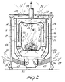
- Figure 1 is a partly sectional perspective view - of a space heater according to the invention;
- Figure 2 is a midsection view schematically illustrating the circulation path of the flue gases relatively to the space heater of Figure 1;
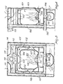
- Figure 3 shows a second diagram of the flue gas circulation path in a modified embodiment with respect to the heater of Figures 1 and 2, the view being taken on a front midplane of the heater; and
- Figure 4 shows a sectional view of the heater of Figure 3, as taken on a parallel plane to the side face thereof.
- Making reference to the drawing figures, a space heater according to the invention comprises an outer enclosing body of glazed ceramic, indicated at 1 and enclosing a metal structure, specifically a cast iron one, which comprises a brazier 2 closed at the front by a
door 3 having aglass window 31 and being fed with combustion air through a slotted grid 4 located on the front wall of theouter body 1, under thedoor 3 and above anash collecting tray 5. Said brazier forms the bottom portion of a combustion chamber orhearth 6 defined laterally by first vertical sidewalls 7 and at the top by a substantiallyhorizontal ceiling 8. Said first walls 7 extend at the bottom from the brazier 2 but end short of theceiling 8 to leave a top side opening 49 for the passage of the flue gases. - The
ceiling 8 is connected laterally to second vertical walls 9 arranged parallel outside of the walls 7 and forming therewith afirst chamber 50 swept by flue gases in a downward direction, as shown by thearrow 10.Additional sidewalls 15, located outside of the walls 9, form with the latter asecond chamber 51 swept by flue gases in an upward direction, as shown by thearrow 11. If desired, to reverse the flue gas flow direction, there may be provided abaffle 12 located at a distance away from the bottom edges of the walls 9 so as to create a bottom side opening 52 and force the flue gases to reverse their direction as shown by thearrow 13. - Provided above the
ceiling 8 is achamber 53 whereinto the flue gases from thechamber 51 are directed and which is connected directly to achimney union 14. - Externally to the
walls 15, there is formed, by means of aparallel sector 16, an air passagevertical chamber 17 which is connected at the top to aninterspace 18 thebase 19 whereof provides separation from the upperflue gas chamber 53, theinterspace 18 being in communication at the top with the ambient air through agrid 20. - The
vertical chamber 17 is connected at the bottom to anintake chamber 21 which is connected to the suction side of aventilating unit 22 the delivery side whereof opens, throughflexible hoses 23, togrids 24 located in the lower portion of the outer enclosingbody 1. - The path of the ambient air forced by the
ventilation unit 22 is shown by theintake arrows 25 which are continued by thedownward flow arrows 26 and hotair ejection arrows 27. - In practice, the hot flue gases generated by the combustion on the brazier 2 rise toward the upper portion of the
combustion chamber 6 and flow downwards along a first downward flow path, to then flow again upwardly toward the chimney, thus delivering their heat to the wall assembly, which are all formed from good heat conducting materials, such as cast iron. - The ambient air is instead picked up from above and sweeps the walls heated by the flue gases in countercurrent relationship to then exhaust downwardly back. to the ambient.
- Figures 3 and 4 show a second embodiment of the invention which incorporates modifications to the flue gas circulation and ambient air chambers.
- With reference to the latter figures, the invention comprises here a
hearth 101 forming the combustion chamber and having a substantially box-like shape with side andrear walls 102, a glassfront access door 103, hearth bottom with agrid 104, and top fluegas exhaust opening 105. - Said top opening 105 communicates with a first inverted-
U chamber 106 which is closed at the bottom by apartition 107, whereat it has aperipheral opening 108 communicating with asecond enveloping chamber 109 open to the outside at its lowermost portion. - The
partition 107 spans partially also saidsecond chamber 109 to form a baffle. - In its upper portion, said
second chamber 109 has anopening 111 which communicates with athird chamber 112 in communication with thechimney 113. - The assembly formed by said three
chambers outer chamber 114 provided at the top with agrid 115 and at the bottom with aconnection 116 with a forcedventilation unit 117. - The
flue gases 118 generated by the combustion supported byoutside air 119 as indicated by the dashed arrows and in turn indicated by full line arrows move upwards toward thetop opening 105, whence they flow down into thefirst chamber 106 as far as thepartition 107, whereat they reverse their direction to flow up into thesecond chamber 109. - The provision of the
baffle 107 which spans partly the chamber allows the outside air indicated by the dash line arrows to become mixed with the flue gases from saidfirst chamber 106. Thebaffle 107, by narrowing the section of thechamber 109 creates a Venturi effect which accelerates the flue gas speed of upflow, said gases, on leaving through theopening 111, flowing into thethird chamber 112 and hence out through thechimney 113. - The ambient air indicated by the dash-and-dot arrows is sucked in countercurrent relationship through the
openings 150 and sweeps the hot chamber exteriors to be returned to the ambient by theventilating unit 117. - The walls of the various chambers 106,109 and 112, which are formed from good heat conductive metal materials, provide a means for transferring the heat from the flue gases to the outer chamber which receives the ambient air.
- The lengthened flue gas path enables the achievement of the highest rate of heat exchange, thereby the flue gases will reach the chimney at a significantly low temperature but sufficient to ensure their ejection to the outside.
- The ambient air sucked in in countercurrent relationship from above is heated, thus recovering a large amount of heat which is then returned to the ambient.
Claims (11)
Priority Applications (1)
| Application Number | Priority Date | Filing Date | Title |
|---|---|---|---|
| AT83107979T ATE24960T1 (en) | 1982-08-27 | 1983-08-12 | STOVE WITH HEAT RECOVERY FROM EXHAUST FUMES. |
Applications Claiming Priority (2)
| Application Number | Priority Date | Filing Date | Title |
|---|---|---|---|
| IT3078582U | 1982-08-27 | ||
| IT8230785U IT8230785V0 (en) | 1982-08-27 | 1982-08-27 | TOTAL HOT AIR RECOVERY FIREPLACE-STOVE. |
Publications (3)
| Publication Number | Publication Date |
|---|---|
| EP0102011A2 true EP0102011A2 (en) | 1984-03-07 |
| EP0102011A3 EP0102011A3 (en) | 1984-10-03 |
| EP0102011B1 EP0102011B1 (en) | 1987-01-14 |
Family
ID=11232027
Family Applications (1)
| Application Number | Title | Priority Date | Filing Date |
|---|---|---|---|
| EP83107979A Expired EP0102011B1 (en) | 1982-08-27 | 1983-08-12 | Fireplace-heater with recovery of heat from the combustion gases |
Country Status (7)
| Country | Link |
|---|---|
| US (1) | US4558688A (en) |
| EP (1) | EP0102011B1 (en) |
| AT (1) | ATE24960T1 (en) |
| CA (1) | CA1213807A (en) |
| DE (1) | DE3369184D1 (en) |
| ES (1) | ES274289Y (en) |
| IT (1) | IT8230785V0 (en) |
Cited By (4)
| Publication number | Priority date | Publication date | Assignee | Title |
|---|---|---|---|---|
| GB2276442A (en) * | 1993-03-08 | 1994-09-28 | Karl Riener | Heating device burning gaseous fuel |
| CN106091373A (en) * | 2016-07-23 | 2016-11-09 | 芜湖长启炉业有限公司 | It is provided with the hexahedro heat exchange air stove of rear wind-break panels |
| EP4001766A1 (en) | 2020-11-13 | 2022-05-25 | Haas + Sohn Ofentechnik GmbH | Method for optimizing the usage of waste heat of a combustion oven |
| DE102022125427A1 (en) | 2022-09-30 | 2024-04-04 | Westfiber Gmbh | Cereal composite articles, in particular oat composite articles, corresponding uses, method and kit |
Families Citing this family (8)
| Publication number | Priority date | Publication date | Assignee | Title |
|---|---|---|---|---|
| BE1003452A3 (en) * | 1987-11-06 | 1992-03-31 | Gerofina Sa | PERIMETRIC RECOVERY OF GASES AND FUMES EMITTED BY A HEATING BODY. |
| US5062411A (en) * | 1990-07-11 | 1991-11-05 | Majco Building Specialties, L.P. | Low pressure drop fireplace heat exchanger |
| US5320086A (en) * | 1993-02-16 | 1994-06-14 | Majco Building Specialties, L.P. | Direct vent gas appliance with vertical and horizontal venting |
| US5673683A (en) * | 1994-08-01 | 1997-10-07 | The Majestic Products Company | Induced draft fireplace |
| DE19601122B4 (en) * | 1996-01-13 | 2006-06-29 | Wodtke Gmbh | Firebox for solid fuels |
| CH694406A5 (en) * | 2000-02-15 | 2004-12-31 | Martin Frei | Fireplace hearth. |
| ES1106930Y (en) * | 2014-04-08 | 2014-07-14 | Lopez German Martinez | FIRE PROTECTION DEVICE IN METALLIC FIREPLACES WITH HEAT USE |
| EP3059503A1 (en) * | 2015-02-20 | 2016-08-24 | Bruno Lampka | Air stream rail |
Family Cites Families (9)
| Publication number | Priority date | Publication date | Assignee | Title |
|---|---|---|---|---|
| US73886A (en) * | 1868-01-28 | Improvement in stoves | ||
| US945994A (en) * | 1908-04-22 | 1910-01-11 | Godfrey Fritz | Furnace. |
| US1869228A (en) * | 1930-07-26 | 1932-07-26 | John C Suber | Furnace |
| BE589135A (en) * | 1959-03-31 | 1960-07-18 | Wilhelmus Antonius Hen Kusters | Fan heater with one or more draft channels. |
| US4010728A (en) * | 1975-06-02 | 1977-03-08 | American Standard, Inc. | Circulating fireplace system |
| US4206743A (en) * | 1977-05-20 | 1980-06-10 | Niemela W Wally | Heating apparatus |
| US4154210A (en) * | 1977-08-24 | 1979-05-15 | Jaymes John B | Wood fired furnace |
| US4217877A (en) * | 1978-09-27 | 1980-08-19 | Uhlyarik Emanuel J | Energy-saving forced-air furnace |
| DE2929715C2 (en) * | 1979-07-21 | 1982-12-23 | H. u. W. Fritzen- GmbH & Co, 4420 Coesfeld | Warm air stove for solid fuels |
-
1982
- 1982-08-27 IT IT8230785U patent/IT8230785V0/en unknown
-
1983
- 1983-08-12 EP EP83107979A patent/EP0102011B1/en not_active Expired
- 1983-08-12 AT AT83107979T patent/ATE24960T1/en not_active IP Right Cessation
- 1983-08-12 DE DE8383107979T patent/DE3369184D1/en not_active Expired
- 1983-08-15 US US06/523,488 patent/US4558688A/en not_active Expired - Lifetime
- 1983-08-26 CA CA000435458A patent/CA1213807A/en not_active Expired
- 1983-08-26 ES ES1983274289U patent/ES274289Y/en not_active Expired
Non-Patent Citations (1)
| Title |
|---|
| None |
Cited By (6)
| Publication number | Priority date | Publication date | Assignee | Title |
|---|---|---|---|---|
| GB2276442A (en) * | 1993-03-08 | 1994-09-28 | Karl Riener | Heating device burning gaseous fuel |
| US5479915A (en) * | 1993-03-08 | 1996-01-02 | Karl Riener | Heating device for gaseous fuels |
| GB2276442B (en) * | 1993-03-08 | 1996-12-04 | Karl Riener | Heating device for gaseous fuels |
| CN106091373A (en) * | 2016-07-23 | 2016-11-09 | 芜湖长启炉业有限公司 | It is provided with the hexahedro heat exchange air stove of rear wind-break panels |
| EP4001766A1 (en) | 2020-11-13 | 2022-05-25 | Haas + Sohn Ofentechnik GmbH | Method for optimizing the usage of waste heat of a combustion oven |
| DE102022125427A1 (en) | 2022-09-30 | 2024-04-04 | Westfiber Gmbh | Cereal composite articles, in particular oat composite articles, corresponding uses, method and kit |
Also Published As
| Publication number | Publication date |
|---|---|
| ES274289U (en) | 1984-01-16 |
| IT8230785V0 (en) | 1982-08-27 |
| ATE24960T1 (en) | 1987-01-15 |
| EP0102011B1 (en) | 1987-01-14 |
| US4558688A (en) | 1985-12-17 |
| CA1213807A (en) | 1986-11-12 |
| ES274289Y (en) | 1984-08-16 |
| DE3369184D1 (en) | 1987-02-19 |
| EP0102011A3 (en) | 1984-10-03 |
Similar Documents
| Publication | Publication Date | Title |
|---|---|---|
| EP0102011A2 (en) | Fireplace-heater with recovery of heat from the combustion gases | |
| US3930490A (en) | Fireplace heater | |
| EP1327825B1 (en) | Improvements in a pellet stove | |
| EP0571446B1 (en) | A solid fuel heating stove | |
| US6021775A (en) | Mobile home furnace | |
| US4042160A (en) | Fireplace form | |
| US4112915A (en) | Fireplace enclosure with heat exchanger | |
| US4386599A (en) | Fireplace stove | |
| US5062411A (en) | Low pressure drop fireplace heat exchanger | |
| US3934554A (en) | Water and room heater | |
| US4102318A (en) | Stratified combustion furnace | |
| US4223833A (en) | Forced air heating fireplace unit | |
| US4020823A (en) | Hot air heating system | |
| US4397292A (en) | Circulating air space heater | |
| CN2092063U (en) | High-efficiency horizontal hot-blast stove burning coal | |
| CN212390349U (en) | Biomass combustion furnace with downward smoke discharging on side surface | |
| CN111981680B (en) | Biomass fired water boiler | |
| US4328784A (en) | Wood and coal burning heating unit | |
| CN217604157U (en) | Wood-burning fireplace | |
| US4535751A (en) | Heat recuperator for fireplace | |
| CA1145632A (en) | Heater | |
| CN2085048U (en) | Multifunctional horizontal coal hot-blast stove | |
| RU2049964C1 (en) | Oven | |
| US4878479A (en) | Apparatus for exhausting the combustion gases of a stove fired on liquid or gaseous fuel | |
| RU2023957C1 (en) | Chimney |
Legal Events
| Date | Code | Title | Description |
|---|---|---|---|
| PUAI | Public reference made under article 153(3) epc to a published international application that has entered the european phase |
Free format text: ORIGINAL CODE: 0009012 |
|
| AK | Designated contracting states |
Designated state(s): AT BE CH DE FR GB LI LU NL |
|
| PUAL | Search report despatched |
Free format text: ORIGINAL CODE: 0009013 |
|
| AK | Designated contracting states |
Designated state(s): AT BE CH DE FR GB LI LU NL |
|
| 17P | Request for examination filed |
Effective date: 19850326 |
|
| GRAA | (expected) grant |
Free format text: ORIGINAL CODE: 0009210 |
|
| AK | Designated contracting states |
Kind code of ref document: B1 Designated state(s): AT BE CH DE FR GB LI LU NL |
|
| REF | Corresponds to: |
Ref document number: 24960 Country of ref document: AT Date of ref document: 19870115 Kind code of ref document: T |
|
| ET | Fr: translation filed | ||
| REF | Corresponds to: |
Ref document number: 3369184 Country of ref document: DE Date of ref document: 19870219 |
|
| PLBE | No opposition filed within time limit |
Free format text: ORIGINAL CODE: 0009261 |
|
| STAA | Information on the status of an ep patent application or granted ep patent |
Free format text: STATUS: NO OPPOSITION FILED WITHIN TIME LIMIT |
|
| 26N | No opposition filed | ||
| EPTA | Lu: last paid annual fee | ||
| REG | Reference to a national code |
Ref country code: GB Ref legal event code: IF02 |
|
| PGFP | Annual fee paid to national office [announced via postgrant information from national office to epo] |
Ref country code: FR Payment date: 20020723 Year of fee payment: 20 |
|
| PGFP | Annual fee paid to national office [announced via postgrant information from national office to epo] |
Ref country code: BE Payment date: 20020725 Year of fee payment: 20 |
|
| PGFP | Annual fee paid to national office [announced via postgrant information from national office to epo] |
Ref country code: DE Payment date: 20020731 Year of fee payment: 20 |
|
| PGFP | Annual fee paid to national office [announced via postgrant information from national office to epo] |
Ref country code: GB Payment date: 20020802 Year of fee payment: 20 |
|
| PGFP | Annual fee paid to national office [announced via postgrant information from national office to epo] |
Ref country code: LU Payment date: 20020828 Year of fee payment: 20 |
|
| PGFP | Annual fee paid to national office [announced via postgrant information from national office to epo] |
Ref country code: NL Payment date: 20020830 Year of fee payment: 20 Ref country code: AT Payment date: 20020830 Year of fee payment: 20 |
|
| PGFP | Annual fee paid to national office [announced via postgrant information from national office to epo] |
Ref country code: CH Payment date: 20020927 Year of fee payment: 20 |
|
| PG25 | Lapsed in a contracting state [announced via postgrant information from national office to epo] |
Ref country code: LI Free format text: LAPSE BECAUSE OF EXPIRATION OF PROTECTION Effective date: 20030811 Ref country code: GB Free format text: LAPSE BECAUSE OF EXPIRATION OF PROTECTION Effective date: 20030811 Ref country code: CH Free format text: LAPSE BECAUSE OF EXPIRATION OF PROTECTION Effective date: 20030811 |
|
| PG25 | Lapsed in a contracting state [announced via postgrant information from national office to epo] |
Ref country code: NL Free format text: LAPSE BECAUSE OF EXPIRATION OF PROTECTION Effective date: 20030812 Ref country code: LU Free format text: LAPSE BECAUSE OF EXPIRATION OF PROTECTION Effective date: 20030812 Ref country code: AT Free format text: LAPSE BECAUSE OF EXPIRATION OF PROTECTION Effective date: 20030812 |
|
| REG | Reference to a national code |
Ref country code: GB Ref legal event code: PE20 |
|
| REG | Reference to a national code |
Ref country code: CH Ref legal event code: PL |
|
| NLV7 | Nl: ceased due to reaching the maximum lifetime of a patent |
Effective date: 20030812 |