EP0101302B1 - System zur Lagesteuerung eines Raumfahrzeugs - Google Patents
System zur Lagesteuerung eines Raumfahrzeugs Download PDFInfo
- Publication number
- EP0101302B1 EP0101302B1 EP83304644A EP83304644A EP0101302B1 EP 0101302 B1 EP0101302 B1 EP 0101302B1 EP 83304644 A EP83304644 A EP 83304644A EP 83304644 A EP83304644 A EP 83304644A EP 0101302 B1 EP0101302 B1 EP 0101302B1
- Authority
- EP
- European Patent Office
- Prior art keywords
- spacecraft
- output
- axis
- filter
- pwpf
- Prior art date
- Legal status (The legal status is an assumption and is not a legal conclusion. Google has not performed a legal analysis and makes no representation as to the accuracy of the status listed.)
- Expired
Links
Images
Classifications
-
- B—PERFORMING OPERATIONS; TRANSPORTING
- B64—AIRCRAFT; AVIATION; COSMONAUTICS
- B64G—COSMONAUTICS; VEHICLES OR EQUIPMENT THEREFOR
- B64G1/00—Cosmonautic vehicles
- B64G1/22—Parts of, or equipment specially adapted for fitting in or to, cosmonautic vehicles
- B64G1/24—Guiding or controlling apparatus, e.g. for attitude control
- B64G1/28—Guiding or controlling apparatus, e.g. for attitude control using inertia or gyro effect
- B64G1/285—Guiding or controlling apparatus, e.g. for attitude control using inertia or gyro effect using momentum wheels
-
- B—PERFORMING OPERATIONS; TRANSPORTING
- B64—AIRCRAFT; AVIATION; COSMONAUTICS
- B64G—COSMONAUTICS; VEHICLES OR EQUIPMENT THEREFOR
- B64G1/00—Cosmonautic vehicles
- B64G1/22—Parts of, or equipment specially adapted for fitting in or to, cosmonautic vehicles
- B64G1/24—Guiding or controlling apparatus, e.g. for attitude control
- B64G1/244—Spacecraft control systems
-
- B—PERFORMING OPERATIONS; TRANSPORTING
- B64—AIRCRAFT; AVIATION; COSMONAUTICS
- B64G—COSMONAUTICS; VEHICLES OR EQUIPMENT THEREFOR
- B64G1/00—Cosmonautic vehicles
- B64G1/22—Parts of, or equipment specially adapted for fitting in or to, cosmonautic vehicles
- B64G1/24—Guiding or controlling apparatus, e.g. for attitude control
- B64G1/36—Guiding or controlling apparatus, e.g. for attitude control using sensors, e.g. sun-sensors, horizon sensors
Definitions
- This invention relates to the field of controlling the attitude of a spacecraft with respect to a set of three orthogonal axes (roll, pitch and yaw).
- EP-A-046 151 relates to a device for the positional stabilisation of vehicles with slightly dampened structural vibrations and intermittent positioning manoeuvres.
- Each axis of the vehicle e.g. a spacecraft, is equipped with a tracking system of at most the third order, a conditional control, and a modulator circuit with relay characteristics.
- the commonly used modulator network with internal modulator return is eliminated and a feedback loop from the output of the modulator takes over the function of these two modulator elements.
- an apparatus for controlling the attitude of a spacecraft with respect to each of three orthogonal reference axes comprising means for imparting angular velocity to the spacecraft about each of three orthogonal spacecraft axes that are fixed with respect to the spacecraft, means for measuring the angular deviation between each spacecraft axis and a corresponding one of the reference axes and for measuring the angular velocity of the spacecraft about each of the spacecraft axes, and means for periodically observing output signals produced by the measuring means and creating in response thereto a digital pulsetrain signature for each spacecraft axis for aligning said spacecraft axis with its corresponding reference axis; wherein each pulsetrain signature is generated by PWPF means situated within said observing and creating means and comprising a filter for smoothing out high frequency transients on the signals produced by the measuring means; and a hysteresis circuit having an input coupled to an output of the filter, wherein the filter's output is subjected to a hystere
- the invention provides a digital system for controlling the attitude of a spacecraft with respect to three orthogonal axes.
- the digital implementation offers the following advantages.
- the digital processor can be shared with other spacecraft functions, saving weight and power.
- long time constant compensation can be represented as preprogrammed elements in a digital computer, saving the weight associated with heavy discrete inductors and capacitors.
- the present invention can be used advantageously during all phases of the launch of spacecraft, e.g., in the case of a satellite, the invention can be used during the parking orbit as an automatic nutation controller; during initial transfer orbit manoeuvres, including sun acquisition, earth acquisition, and apogee motor firing; and during all phases of attitude control in final operational orbit, including station-keeping maneuvers and momentum wheel unloading.
- the invention can be used whether or not spacecraft utilises momentum wheels for stiffening momentum about one or more of the orthogonal axes.
- momentum wheels part of the present circuit can be used for momentum dumping in the momentum wheel control mode.
- the present invention achieves better resolution of attitude control than prior art systems.
- this is attributable to the PWPF apparatus comprising the processor, filters, limiter circuits, hysteresis circuits, and data registers.
- a PWPF loop for each axis is actuated once for each thruster command period T2 (there are preferably several T2's per processed error cycle period T1, to improve resolution).
- T2 a thruster pulse train signature for instructing each thruster whether and when to fire during the next T1.
- a thruster pulse train signature is a sophisticated sequence of a variable number of logical plus one pulses, minus one pulses, and zero level pulses, each having variable width.
- a set of pulse train signatures is loaded into shift registers each T1 and outputted to the spacecraft thruster coils each T3, where T3 is preferably less than T2 to minimize the impact of synchronization errors.
- Data extenders are serially connected to shift registers and ensure that there is continuity between each T1's series of pulses so that the thruster valves do not unnecessarily open and close.
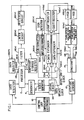
- spacecraft 14 which can be a missile but for the purposes of this discussion is assumed to be a satellite, must be stabilized about three orthogonal axes commonly designated roll, pitch, and yaw.
- Attitude sensors 12 measure the angular deviation of spacecraft 14 with respect to the desired orientation of each of the three axes, e.g., by means of earth sensors and sun sensors. Sensors 12 further measure the angular velocity of spacecraft 14 about each of the three axes, e.g., by means of rate gyros.
- These six signals are fed by attitude sensors 12 into control loop compensation electronics 10, which weights the angular deviation and the angular velocity signals according to their relative importance in attitude control according to control laws.
- Compensation electronics 10 also contains circuitry to insure that the frequency of thruster firings on board spacecraft 14 does not interact with the structural frequencies of spacecraft 14 to cause instability.
- Sequencer 4 is a controller such as a programmed digital computer which bidirectionally communicates with processor 2. Every T1, sequencer 4 sends a first signal informing gating circuit 36 that a processed error cycle has ended, and sends a second signal to processor 2 instructing it to accept new data from register 8 and commence actuation of a new round of PWPF loops. Said first signal could also be sent directly from clock generator 34 to gating circuit 36. Sequencer 4 also acts as a time sharing interface so that other functions (not illustrated here) associated with controlling spacecraft 14, such as TT&C, magnetic control torquer loops, etc., can also use the services of processor 2 on a time shared basis. As mentioned above, this is a major advantage of employing this digital attitude control system because it enables an overall savings of weight and power on board spacecraft 14.
- Processor 2 is essentially a microprocessor arithmetic logic unit. It communicates bidirectionally with temporary storage register 6, typically a RAM scratchpad memory used for making calculations and for storing, for each of the three axes, the output of the last PWPF loop of each processed error cycle for use in the first PWPF loop for the next processed error cycle.
- temporary storage register 6 typically a RAM scratchpad memory used for making calculations and for storing, for each of the three axes, the output of the last PWPF loop of each processed error cycle for use in the first PWPF loop for the next processed error cycle.
- the PWPF apparatus which performs PWPF loops for all three axes, comprises processor 2, three filters 16 (one for each axis), three limiter circuits 20 (one for each axis), three hysteresis circuits 22 (one for each axis), and three data registers 24 (one for each axis).
- Fig. 1 illustrates just one each of items 16, 20, 22, and 24 using the letter n in parenthesis to indicate that the item illustrated is but one of three siblings.
- n means one of 1, 2, and 3, representing roll, pitch, and yaw, respectively.
- Wires 18 connect processor 2 with filters 16; wires 26 connect registers 24 with processor 2.
- n 1,2,3, the output of filter 16(n) is connected to the input of limiter circuit 20(n), the output of which is connected to the input of hysteresis circuit 22(n), the output of which is connected to the input of data register 24(n).
- the amount of time assigned to the output of each PWPF loop for each axis is designated the thruster command period T2. It is desirable that T2 be smaller than T1 to improve thruster command signal resolution, although T2 could equal T1.
- T1 4T2, i.e., T2 is 16 milliseconds.
- a PWPF loop for each axis is actuated four times during each T1.
- the output of each of these twelve negative feedback loops is either a logical +1, -1, or 0. +1 indicates that the positive thruster for that axis, but not the negative thruster, should be fired.
- -1 indicates that the negative thruster for that axis, but not the positive thruster, should be fired.
- T1/T2 outputs of each PWPF loop constitute one T1's-worth of the thruster pulsetrain signature for the thruster associated with that axis.
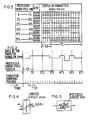
- a typical pulsetrain signature is show in Fig. 2 over a time of 6T1.
- spacecraft 14 has six thrusters (or other angular velocity imparting means) positioned to impart angular velocity to spacecraft 14 about each of the three axes in each of a positive rotational sense and an opposite negative rotational sense.
- the thrusters impart motion to spacecraft 14 pursuant to Newtonian laws of physics, typically by firing a gas. The firing may be actuated by electrically charging a coil associated with the selected thruster.
- sign detector 28(n) determines the sign of each output of the PWPF loop (typically stored as the most significant bit of the data word presented to the input of 28(n)) and gates the sign information to sign formatter 30(n).
- sign formatter 30(n) Each of the three formatters 30/32 stores the pulsetrain signature for one of the axes and breaks it up into smaller bits.
- a minus sign is represented as a logical one and a plus sign is represented as a logical zero within sign formatter 30(n).
- Sign detector 28(n) also extracts the amplitude information from the output of each PWPF loop (typically the least significant bit of the data word presented at the input of 28(n)) and gates this information, either a logical one or a logical zero, to amplitude formatter 32(n).
- Formatters 30/32 are each typically serial-in parallel-out shift registers in combination with data splitters.
- the input shift register portion of each formatter has T1/T2 columns, one for each of the PWPF loop outputs produced each T1. In the example discussed herein, the number of columns is 4.
- the data splitter portion of each formatter 30, 32 can be, e.g., simply a set of wires to split each data bit into T2/T3 clone data bits, where T3 is the period of the Output Shift Clock used to output data from shift registers 44 and 46.
- the reason for the data splitting is to minimize the impact of synchronization discrepancies between the Output Shift Clock and the Data Update Clock used to load data into registers 44, 46; e.g., with the data splitting, an error of duration T3 would be made due to a missed clock pulse, rather than an error of duration T2.
- T3 is four milliseconds, so each thruster pulsetrain signature residing within a formatter 30 or 32 has sixteen bits for each period of time T1. Within each period of time T2, all bits are the same. This is shown in Fig. 3 for the signature depicted in Fig. 2.
- Clock generator 34 produces all the clocks necessary for timing the Fig. 1 circuit, starting with a first clock at the fastest rate needed by the circuit. In the embodiment illustrated, this fastest clock signal is 500 KHz. and is sent to gating circuit 36. This is the rate at which the Data Update Clock loads extenders 40 and 42 and registers 44 and 46 from formatters 30 and 32. Clock generator 34 divides the fastest clock into three slower clocks, e.g., by a set of flip-flops. These clocks have periods of T1, T2, and T3, respectively. The T3 clock signal is also sent to gating circuit 36 where it is subsequently used as the constantly-running Output Shift Clock. The T1 and T2 clock signals are sent to sequencer 4.
- Gating circuit 36 receives a signal from sequencer 4 (or generator 34) at the end of each T1 period, and in response to this signal, actuates T1/T3+x cycles of the Data Update Clock, causing Tl/T3+x bits from each amplitude formatter 32(n) to be read into data extenders 40(n) and 42(n) and shift registers 44(n) and 46(n).
- a bit from amplitide formatter 32(n) will be read into the combined register consisting of positive data extender 40(n) and positive shift register 44(n) if the sign of that bit, as evidenced by the corresponding bit position within sign formatter 30(n), is zero.
- a bit from amplitude formatter 32(n) will be read into the combined register consisting of negative data extender 42(n) and negative shift register 46(n) if the sign of that bit is negative, as evidenced by a logical 1 appearing in the corresponding bit position for sign formattter 30(n).
- This gating into the positive versus the negative logic is accomplished by means of gating circuitry for each axis consisting of inverter 37(n) and AND gates 38(n) and 39(n).
- the output of sign formatter 30(n) is connected to the input of inverter 37(n) and to a first input of AND gate 39(n).
- the output of amplitude formatter 32(n) is connected to the second input of AND gate 39(n) and to a first input of AND gate 38(n).
- the output of inverter 37(n) is connected to the second input of AND gate 38(n).
- the output of AND gate 38(n) is connected to the input of positive data extender 40(n) and the output of AND gate 39(n) is connected to the input of negative data extender 42(n).
- x should be at least 1. In the illustrated embodiment, x was chosen to be 2.
- 18 pulses of the Data Update Clock are activated, loading 18 bits from amplitude formatter 32(n) into data extenders 40(n), 42(n) and shift registers 44(n), 46(n).
- Shift registers 44, 46 are all serial-out shift registers whose output shifting is controlled by the Output Shift Clock and whose input loading is controlled by the Data Update Clock.
- Data extenders 40, 42 are, e,g., latches, and each imparts a delay of xT3. Extenders 40, 42 are also loaded by the Data Update Clock and shifted out by the Output Shift Clock.
- Each positive data extender 40(n) is connected in series with a positive shift register 44(n) and each negative data extender 42(n) is connected in series with a negative shift register 46(n), making composite shift registers of 18 bit positions each for the example illustrated.
- the last bit to be loaded into its associated shift register is repeated twice by the data extender. For example, if the 16th bit shifted into positive shift register 44(1) is a 1, then the two bits within positive data extender 40(1) are also 1's.
- the reason for the redundancy provided by the data extenders is to provide continuity between processed error cycles, avoiding data gaps in case, e.g., the signal to gating circuit 36 announcing the end of a processed error cycle arrives late. By this means, unwanted turn-on's and turn-off's of thrusters is avoided.
- a positive output bit from a register 44 or 46 is typically an electrical signal having a potential of 5 volts, indicating that a thruster is desired to be actuated for that time T3, which a logical zero output bit is an electrical signal having zero volts.
- the three positive high side drivers 48 and the three negative high side drivers 50 simply serve to increase the 5 volt signals to a higher level more suitable for spacecraft 14, e.g., 26 volts, to overcome noise and transients on spacecraft 14, while passing-through zero volt signals unchanged.
- the six high side drivers 48 and 50 can be voltage translators.
- a signal is fed from the positive high side driver 48(n) and the negative high side driver 50(n) to a positive thruster valve coil driver 52(n) and a negative thruster valve coil driver 54(n), respectively.
- Each driver 52, 54 typically increases the voltage for a logical one to 42 volts, applying this voltage to a thruster coil which energizes the proper thruster.
- a zero volt output from a high side driver 48, 50 results in a zero volt output from its associated coil driver 52, 54, which deactivates the associated thruster.
- Each filter 16 is typically a single-pole low pass integrating filter having a transfer function of the form K/(TS+ 1 ), where S is the integrating operator, T is a time constant, and K is proportional to the gain. Filter 16 smooths out high frequency voltage excursions on the input error signal. Filter 16 can be implemented as part of a digital computer, e.g., each filter 16 can be part of processor 2. In an analog embodiment, filter 16 might have a capacitor and an inductor. The output from each filter 16 is designated AI and becomes the input to its corresponding limiter 20, the function of which is shown is Fig. 4, wherein the input is represented as being along the X axis and the output along the Y axis.
- limiter 20 If the absolute value of A1 is less than or equal to pre-established threshold A5, A1 will pass through limiter 20 unchanged, because the slope of the limiter's curve in the vicinity of the axes' intersection is one. Positive values of A1 in excess of A5 are limited to A5, and negative values of A1 less than -A5 are limited to -A5.
- the function of limiter 20 is to lower the recovery time of the loop.
- Such limiters 20 are conventionally available in digital hardware.
- An analog example of such a filter is a pair of back-to-back Zener diodes.
- each limiter 20 is passed to the hysteresis circuit 22 for that axis, shown schematically in Fig. 5. Assume that the initial input and output for circuit 22 are each zero, and the input starts to increase. Once the input exceeds A7, the output of circuit 22 will be a 1. The output of circuit 22 will remain high as the input decreases below A7 until the input reaches -A6, whereupon the output of circuit 22 will become zero. As the input declines even further, the output of circuit 22 will remain zero until the input is less than -A7, whereupon the output of circuit 22 will be -1.
- the output of circuit 22 will remain a -1 until such time as the input exceeds A6, whereupon the output of circuit 22 will become zero. It is desirable to vertically overlap the hysteresis loop (e.g., a zero input can result in a -1, 0, or 1 output depending upon the input's history) because overlapping 'the hysteresis loop modifies its phase relationship with respect to the error signal from register 8 and improves the phase margin of the compensation.
- Each data register 24 is the recipient of the output produced by its corresponding hysteresis circuit 22. This output is fed to processor 2, is inverted, and is added to the portion of the error signal received from data register 8 for that axis for inputting to filter 16 as the error input for the next iteration of the PWPF loop for that axis. This negative feedback via register 24 is used even when said next PWPF loop iteration occurs during the next T1 interval, i.e.. the data from register 8 has been updated.
- PROM programmable read-only memory
- Line 11 of the program embodies the operation of filter 16(n) with constants supplied by sequencer 4.
- Lines 13 and 14 embody the function of limiter circuit 20(n)
- lines 15 through 18 embody the functioning of hysteresis circuit 22, and lines 20-22 embody formatting and sign assignment.
- This one PROM program embodies the PWPF loops for all three axes; the individual constants for each loop are fed into the PROM by sequencer 4.
- Sequencer 4 could command processor 2 to perform the PWPF loops in any order.
- the twelve PWPF loops are separated axis-wise so that the four roll loops are first performed, followed by the four pitch loops, then the four yaw loops.
- Each of the PWPF loop outputs corresponds to the 16 milliseconds of the thruster command period, while the execution of each loop takes just one millisecond of processor 2 time. The remaining processor 2 time is used to perform other spacecraft 14 functions, as described above.
Landscapes
- Engineering & Computer Science (AREA)
- Remote Sensing (AREA)
- Chemical & Material Sciences (AREA)
- Combustion & Propulsion (AREA)
- Radar, Positioning & Navigation (AREA)
- Aviation & Aerospace Engineering (AREA)
- Automation & Control Theory (AREA)
- Control Of Position, Course, Altitude, Or Attitude Of Moving Bodies (AREA)
Claims (5)
wobei jedes Impulsfolgenkennsignal durch in den besagten Beobachtungs- und Erzeugungsmitteln (2, 16, 20, 30, 32) befindliche PWPF-Mittel erzeugt wird sowie:
Applications Claiming Priority (2)
| Application Number | Priority Date | Filing Date | Title |
|---|---|---|---|
| US06/407,196 US4599697A (en) | 1982-08-11 | 1982-08-11 | Digital PWPF three axis spacecraft attitude control |
| US407196 | 1995-03-20 |
Publications (3)
| Publication Number | Publication Date |
|---|---|
| EP0101302A2 EP0101302A2 (de) | 1984-02-22 |
| EP0101302A3 EP0101302A3 (en) | 1985-07-31 |
| EP0101302B1 true EP0101302B1 (de) | 1989-09-27 |
Family
ID=23611032
Family Applications (1)
| Application Number | Title | Priority Date | Filing Date |
|---|---|---|---|
| EP83304644A Expired EP0101302B1 (de) | 1982-08-11 | 1983-08-11 | System zur Lagesteuerung eines Raumfahrzeugs |
Country Status (5)
| Country | Link |
|---|---|
| US (1) | US4599697A (de) |
| EP (1) | EP0101302B1 (de) |
| JP (2) | JPS5984700A (de) |
| CA (1) | CA1196075A (de) |
| DE (1) | DE3380641D1 (de) |
Families Citing this family (40)
| Publication number | Priority date | Publication date | Assignee | Title |
|---|---|---|---|---|
| US4537375A (en) * | 1983-04-21 | 1985-08-27 | Ford Aerospace & Communications Corporation | Method and apparatus for thruster transient control |
| US4758957A (en) * | 1985-05-17 | 1988-07-19 | General Electric Company | Spacecraft stabilization system and method |
| US4725024A (en) * | 1985-11-15 | 1988-02-16 | Ford Aerospace & Communications Corporation | Method for spinning up a three-axis controlled spacecraft |
| WO1989002622A1 (fr) * | 1987-09-16 | 1989-03-23 | Messerschmitt-Bölkow-Blohm Gesellschaft Mit Beschr | Dispositif de regulation de valeur de consigne et/ou de stabilisation de corps librement en mouvement a giration latente |
| US4931942A (en) * | 1988-05-26 | 1990-06-05 | Ford Aerospace Corporation | Transition control system for spacecraft attitude control |
| US4961551A (en) * | 1988-11-18 | 1990-10-09 | Hughes Aircraft Company | Stabilization of a spinning spacecraft of arbitary shape |
| US4949922A (en) * | 1988-12-09 | 1990-08-21 | Hughes Aircraft Company | Satellite control system |
| US5124925A (en) * | 1990-01-16 | 1992-06-23 | Space Systems/Loral, Inc. | Method for controlling east/west motion of a geostationary satellite |
| US5130931A (en) * | 1990-07-13 | 1992-07-14 | General Electric Company | Spacecraft attitude and velocity control system |
| EP0496879B1 (de) * | 1990-08-22 | 1995-04-26 | Microcosm, Inc. | Vorrichtung zum halten eines satelliten auf seiner umlaufbahn |
| US5140525A (en) * | 1991-07-31 | 1992-08-18 | General Electric Company | Unified spacecraft attitude control system |
| CA2076894C (en) * | 1991-11-27 | 1998-11-03 | John F. Yocum | Three axis thruster modulation |
| US5311435A (en) * | 1991-11-27 | 1994-05-10 | Hughes Aircraft Company | Method for station keeping control of flexible spacecraft using onboard gain scheduling scheme |
| DE4210966C2 (de) * | 1992-04-02 | 1994-06-23 | Deutsche Aerospace | Verfahren zur digitalen Modulation |
| US5687084A (en) * | 1992-05-26 | 1997-11-11 | Microcosm, Inc. | Satellite orbit maintenance system |
| US5335179A (en) * | 1992-12-24 | 1994-08-02 | General Electric Co. | Unified spacecraft attitude control system with pseudo-complementary paired thrusters |
| US5456429A (en) * | 1993-08-02 | 1995-10-10 | Loral Corp. | Thrust maneuver system |
| US5459669A (en) * | 1994-02-14 | 1995-10-17 | Space Systems/Loral, Inc. | Control system and method for spacecraft attitude control |
| US5646847A (en) * | 1995-08-25 | 1997-07-08 | Martin Marietta Corp. | Universal thruster selection logic for spacecraft attitude control |
| US5810295A (en) * | 1996-07-10 | 1998-09-22 | Hughes Electronics Corporation | Method and apparatus for a satellite station keeping |
| US6023291A (en) * | 1996-10-16 | 2000-02-08 | Space Systems/Loral, Inc. | Satellite camera attitude determination and image navigation by means of earth edge and landmark measurement |
| US6000661A (en) * | 1996-10-16 | 1999-12-14 | Space Systems/Loral, Inc. | Autonomous spacecraft payload base motion estimation and correction |
| US5996942A (en) * | 1996-10-16 | 1999-12-07 | Space Systems/Loral, Inc. | Autonomous solar torque management |
| US6068217A (en) * | 1996-10-16 | 2000-05-30 | Space Systems/Loral, Inc. | Method to reorient a spacecraft using only initial single axis attitude knowledge |
| WO1998032657A1 (en) | 1997-01-27 | 1998-07-30 | Space Systems/Loral, Inc. | Spacecraft attitude control system using low thrust thrusters |
| US5957411A (en) * | 1997-01-31 | 1999-09-28 | Space Systems/Loral, Inc. | Method using double thruster firings to deadbeat flexible solar array structural oscillations |
| WO1998033704A2 (en) | 1997-02-04 | 1998-08-06 | Belbruno Edward A | Computer implemented procedure for ballistic capture transfer |
| US6097997A (en) * | 1997-03-25 | 2000-08-01 | Galaxy Development, Llc | Low energy method for changing the inclinations of orbiting satellites using weak stability boundaries and a computer process for implementing same |
| AU7357198A (en) | 1997-03-25 | 1998-10-20 | Edward A. Belbruno | Low energy method for changing the inclinations of orbiting satellites using weak stability boundaries and a computer process for implementing same |
| EA002665B1 (ru) * | 1997-04-24 | 2002-08-29 | Галакси Девелопмент, Ллс | Способ изменения наклонения и высоты орбиты космического летательного аппарата с использованием границ области малой устойчивости |
| US6125310A (en) * | 1997-07-18 | 2000-09-26 | Space Systems/Loral, Inc. | Thruster on time signaling with flexure compensation avoidance |
| US6385512B1 (en) | 1999-04-16 | 2002-05-07 | Galaxy Development Llc | System and method of a ballistic capture transfer to L4, L5 |
| US6191728B1 (en) * | 1999-07-07 | 2001-02-20 | Honeywell International Inc. | Agile satellite targeting |
| GB2384313A (en) * | 2002-01-18 | 2003-07-23 | Qinetiq Ltd | An attitude sensor |
| JP4463287B2 (ja) * | 2007-02-07 | 2010-05-19 | Nec東芝スペースシステム株式会社 | 姿勢変更制御方法、姿勢変更制御システム、姿勢変更制御プログラムおよびプログラム記録媒体 |
| US20090039202A1 (en) * | 2007-02-07 | 2009-02-12 | Keita Ogo | Attitude Change Control Method, Attitude Change Control System, Attitude Change Control Program and Program Recording Medium |
| CN101513939B (zh) * | 2009-04-03 | 2011-01-05 | 北京航空航天大学 | 一种合成孔径雷达卫星的二维姿态控制系统 |
| RU2568527C1 (ru) * | 2014-10-17 | 2015-11-20 | Федеральное государственное унитарное предприятие "Научно-производственное объединение им. С.А. Лавочкина" | Система стабилизации космического аппарата |
| US10404239B2 (en) | 2016-06-03 | 2019-09-03 | Caterpillar Inc. | Control system for controlling operation of a machine by imposing shaped hysterisis |
| CN109739262B (zh) * | 2019-01-25 | 2022-04-19 | 上海微小卫星工程中心 | 一种快速自主转移轨道控制方法 |
Family Cites Families (15)
| Publication number | Priority date | Publication date | Assignee | Title |
|---|---|---|---|---|
| US3206141A (en) * | 1961-09-29 | 1965-09-14 | Hugh L Dryden | Space vehicle attitude control |
| US3547381A (en) * | 1967-12-29 | 1970-12-15 | Ball Brothers Res Corp | Three-axis orientation system |
| US3636411A (en) * | 1968-05-28 | 1972-01-18 | Bendix Corp | Control logic switching for an on-off controller |
| US3643897A (en) * | 1968-10-18 | 1972-02-22 | Communications Satellite Corp | Nutation correction system for spin-stabilized satellite |
| US3578957A (en) * | 1969-05-29 | 1971-05-18 | Nasa | Sampled data controller |
| US3866025A (en) * | 1972-03-17 | 1975-02-11 | Rca Corp | Spacecraft attitude control system |
| US3944172A (en) * | 1972-04-14 | 1976-03-16 | Erno Raumfahrttechnik Gmbh | Attitude control for space vehicle |
| US4012018A (en) * | 1973-10-04 | 1977-03-15 | The United States Of America As Represented By The Administrator Of The National Aeronautics And Space Administration | All sky pointing attitude control system |
| US3937423A (en) * | 1974-01-25 | 1976-02-10 | Hughes Aircraft Company | Nutation and roll error angle correction means |
| US4071211A (en) * | 1976-09-23 | 1978-01-31 | Rca Corporation | Momentum biased active three-axis satellite attitude control system |
| DE2732201C2 (de) * | 1977-07-16 | 1983-01-13 | Messerschmitt-Bölkow-Blohm GmbH, 8000 München | Regler für die Lagestabilisierung eines Satelliten |
| DE2749868C3 (de) * | 1977-11-08 | 1980-05-22 | Messerschmitt-Boelkow-Blohm Gmbh, 8000 Muenchen | Sonnen- und Erderfassungsverfahren für Satelliten |
| US4161780A (en) * | 1978-06-23 | 1979-07-17 | The United States Of America As Represented By The Secretary Of The Navy | Spin rate timing system |
| EP0046151B1 (de) * | 1980-08-19 | 1985-11-21 | Messerschmitt-Bölkow-Blohm Gesellschaft mit beschränkter Haftung | Vorrichtung zur Lagestabilisierung von elastischen Fahrzeugen |
| US4396878A (en) * | 1981-07-13 | 1983-08-02 | General Dynamics, Pomona Division | Body referenced gimballed sensor system |
-
1982
- 1982-08-11 US US06/407,196 patent/US4599697A/en not_active Expired - Fee Related
-
1983
- 1983-07-25 CA CA000433068A patent/CA1196075A/en not_active Expired
- 1983-08-11 EP EP83304644A patent/EP0101302B1/de not_active Expired
- 1983-08-11 DE DE8383304644T patent/DE3380641D1/de not_active Expired
- 1983-08-11 JP JP58145815A patent/JPS5984700A/ja active Pending
-
1992
- 1992-07-02 JP JP1992052059U patent/JP2542390Y2/ja not_active Expired - Lifetime
Also Published As
| Publication number | Publication date |
|---|---|
| JP2542390Y2 (ja) | 1997-07-23 |
| EP0101302A3 (en) | 1985-07-31 |
| EP0101302A2 (de) | 1984-02-22 |
| JPH0575099U (ja) | 1993-10-12 |
| CA1196075A (en) | 1985-10-29 |
| JPS5984700A (ja) | 1984-05-16 |
| DE3380641D1 (en) | 1989-11-02 |
| US4599697A (en) | 1986-07-08 |
Similar Documents
| Publication | Publication Date | Title |
|---|---|---|
| EP0101302B1 (de) | System zur Lagesteuerung eines Raumfahrzeugs | |
| EP0071445B1 (de) | Elektronische Steuerung der Roll- und Gierbewegungen von Satelliten in einer Umlaufbahn | |
| JP2914998B2 (ja) | 宇宙機姿勢制御装置用遷移制御システム | |
| US5400033A (en) | Tracking system for tracking targets with a spacecraft | |
| GB2040513A (en) | Active nutation control system for space vehicle | |
| JPH06227498A (ja) | 宇宙飛行体の南北定置操縦間の東西軌道制御装置 | |
| US5957411A (en) | Method using double thruster firings to deadbeat flexible solar array structural oscillations | |
| DE69120515T2 (de) | Aktive Steuerung der Drallachse für drallstabilisierte Raumfahrzeuge | |
| US5860625A (en) | Aircraft frequency adaptive modal suppression system | |
| EP0772108B1 (de) | Verfahren und System zur Steuerung der Lage oder der Orientierung eines Raumfahrzeuges | |
| DE69721370T2 (de) | Drallvektorsteuerung für Satellit mit Drallsensor | |
| Grasshoff | An onboard, closed-loop, nutation control system for a spin-stabilized spacecraft. | |
| Martin | Closed-loop near-optimum/steering for a class of space missions. | |
| Ih et al. | Experiments in multivariable adaptive control of a large flexible structure | |
| Gupta et al. | Development of navigation guidance and control technology for Indian launch vehicles | |
| Vaeth | Compatibility of impulse modulation techniques with attitude sensor noise and spacecraft maneuvering | |
| Lebsock | High pointing accuracy with a momentum bias attitude control system | |
| Henson et al. | Digital simulation by partitioning and uncoupling the system model | |
| DE2539457C2 (de) | Verfahren und Steuersystem zum Eliminieren der Nutation eines Raumflugkörpers | |
| Chilton | Apollo spacecraft control systems | |
| Miller | Targeting an optimal lunar transfer trajectory using ballistic capture | |
| Deyst | A survey of structural flexibility effects on spacecraft control systems | |
| Singh | Effect of damping on the structure of the time-optimal control profile | |
| SCHROER | DESIGN OF A STANDARD LAUNCH VEHICLE CONTROL SYSTEM | |
| Sullivan et al. | A new satellite attitude control system |
Legal Events
| Date | Code | Title | Description |
|---|---|---|---|
| PUAI | Public reference made under article 153(3) epc to a published international application that has entered the european phase |
Free format text: ORIGINAL CODE: 0009012 |
|
| AK | Designated contracting states |
Designated state(s): DE FR GB |
|
| PUAL | Search report despatched |
Free format text: ORIGINAL CODE: 0009013 |
|
| AK | Designated contracting states |
Designated state(s): DE FR GB |
|
| 17P | Request for examination filed |
Effective date: 19860127 |
|
| 17Q | First examination report despatched |
Effective date: 19870928 |
|
| GRAA | (expected) grant |
Free format text: ORIGINAL CODE: 0009210 |
|
| AK | Designated contracting states |
Kind code of ref document: B1 Designated state(s): DE FR GB |
|
| REF | Corresponds to: |
Ref document number: 3380641 Country of ref document: DE Date of ref document: 19891102 |
|
| ET | Fr: translation filed | ||
| PLBE | No opposition filed within time limit |
Free format text: ORIGINAL CODE: 0009261 |
|
| STAA | Information on the status of an ep patent application or granted ep patent |
Free format text: STATUS: NO OPPOSITION FILED WITHIN TIME LIMIT |
|
| 26N | No opposition filed | ||
| REG | Reference to a national code |
Ref country code: GB Ref legal event code: 732E |
|
| REG | Reference to a national code |
Ref country code: FR Ref legal event code: TP |
|
| PGFP | Annual fee paid to national office [announced via postgrant information from national office to epo] |
Ref country code: FR Payment date: 19970721 Year of fee payment: 15 |
|
| PGFP | Annual fee paid to national office [announced via postgrant information from national office to epo] |
Ref country code: DE Payment date: 19970722 Year of fee payment: 15 |
|
| PGFP | Annual fee paid to national office [announced via postgrant information from national office to epo] |
Ref country code: GB Payment date: 19970728 Year of fee payment: 15 |
|
| PG25 | Lapsed in a contracting state [announced via postgrant information from national office to epo] |
Ref country code: GB Free format text: LAPSE BECAUSE OF NON-PAYMENT OF DUE FEES Effective date: 19980811 |
|
| GBPC | Gb: european patent ceased through non-payment of renewal fee |
Effective date: 19980811 |
|
| PG25 | Lapsed in a contracting state [announced via postgrant information from national office to epo] |
Ref country code: FR Free format text: LAPSE BECAUSE OF NON-PAYMENT OF DUE FEES Effective date: 19990430 |
|
| PG25 | Lapsed in a contracting state [announced via postgrant information from national office to epo] |
Ref country code: DE Free format text: LAPSE BECAUSE OF NON-PAYMENT OF DUE FEES Effective date: 19990601 |
|
| REG | Reference to a national code |
Ref country code: FR Ref legal event code: ST |