EP0101192A2 - Modul für ein klinisches Analysiergerät - Google Patents
Modul für ein klinisches Analysiergerät Download PDFInfo
- Publication number
- EP0101192A2 EP0101192A2 EP83304116A EP83304116A EP0101192A2 EP 0101192 A2 EP0101192 A2 EP 0101192A2 EP 83304116 A EP83304116 A EP 83304116A EP 83304116 A EP83304116 A EP 83304116A EP 0101192 A2 EP0101192 A2 EP 0101192A2
- Authority
- EP
- European Patent Office
- Prior art keywords
- test module
- serum
- cup
- dilution
- valve
- Prior art date
- Legal status (The legal status is an assumption and is not a legal conclusion. Google has not performed a legal analysis and makes no representation as to the accuracy of the status listed.)
- Granted
Links
- 238000012360 testing method Methods 0.000 title claims abstract description 73
- 239000000523 sample Substances 0.000 claims abstract description 73
- 210000002966 serum Anatomy 0.000 claims abstract description 63
- 239000012895 dilution Substances 0.000 claims abstract description 52
- 238000010790 dilution Methods 0.000 claims abstract description 52
- 239000000463 material Substances 0.000 claims abstract description 38
- 239000003153 chemical reaction reagent Substances 0.000 claims abstract description 37
- 238000006243 chemical reaction Methods 0.000 claims abstract description 32
- 239000007788 liquid Substances 0.000 claims abstract description 25
- 238000002835 absorbance Methods 0.000 claims description 3
- 238000010438 heat treatment Methods 0.000 claims 1
- 238000003556 assay Methods 0.000 abstract description 9
- 238000003018 immunoassay Methods 0.000 abstract description 4
- 230000008878 coupling Effects 0.000 description 13
- 238000010168 coupling process Methods 0.000 description 13
- 238000005859 coupling reaction Methods 0.000 description 13
- 238000004458 analytical method Methods 0.000 description 7
- GNBHRKFJIUUOQI-UHFFFAOYSA-N fluorescein Chemical compound O1C(=O)C2=CC=CC=C2C21C1=CC=C(O)C=C1OC1=CC(O)=CC=C21 GNBHRKFJIUUOQI-UHFFFAOYSA-N 0.000 description 5
- 238000010998 test method Methods 0.000 description 5
- 102000004190 Enzymes Human genes 0.000 description 4
- 108090000790 Enzymes Proteins 0.000 description 4
- 239000003814 drug Substances 0.000 description 4
- 229940079593 drug Drugs 0.000 description 4
- 238000011534 incubation Methods 0.000 description 4
- 239000000203 mixture Substances 0.000 description 4
- 239000002184 metal Substances 0.000 description 3
- 230000000295 complement effect Effects 0.000 description 2
- 239000012530 fluid Substances 0.000 description 2
- 238000000034 method Methods 0.000 description 2
- 238000012986 modification Methods 0.000 description 2
- 230000004048 modification Effects 0.000 description 2
- 230000002441 reversible effect Effects 0.000 description 2
- 230000000007 visual effect Effects 0.000 description 2
- 239000004677 Nylon Substances 0.000 description 1
- 238000010521 absorption reaction Methods 0.000 description 1
- 238000013096 assay test Methods 0.000 description 1
- 238000010276 construction Methods 0.000 description 1
- 238000013461 design Methods 0.000 description 1
- 239000012470 diluted sample Substances 0.000 description 1
- 239000012153 distilled water Substances 0.000 description 1
- 230000005284 excitation Effects 0.000 description 1
- 239000011344 liquid material Substances 0.000 description 1
- 238000000691 measurement method Methods 0.000 description 1
- 229920001778 nylon Polymers 0.000 description 1
- 239000004033 plastic Substances 0.000 description 1
- 102000004169 proteins and genes Human genes 0.000 description 1
- 108090000623 proteins and genes Proteins 0.000 description 1
- 238000004611 spectroscopical analysis Methods 0.000 description 1
- 239000002699 waste material Substances 0.000 description 1
- XLYOFNOQVPJJNP-UHFFFAOYSA-N water Chemical compound O XLYOFNOQVPJJNP-UHFFFAOYSA-N 0.000 description 1
Images
Classifications
-
- G—PHYSICS
- G01—MEASURING; TESTING
- G01N—INVESTIGATING OR ANALYSING MATERIALS BY DETERMINING THEIR CHEMICAL OR PHYSICAL PROPERTIES
- G01N35/00—Automatic analysis not limited to methods or materials provided for in any single one of groups G01N1/00 - G01N33/00; Handling materials therefor
- G01N35/10—Devices for transferring samples or any liquids to, in, or from, the analysis apparatus, e.g. suction devices, injection devices
- G01N35/1081—Devices for transferring samples or any liquids to, in, or from, the analysis apparatus, e.g. suction devices, injection devices characterised by the means for relatively moving the transfer device and the containers in an horizontal plane
- G01N35/1083—Devices for transferring samples or any liquids to, in, or from, the analysis apparatus, e.g. suction devices, injection devices characterised by the means for relatively moving the transfer device and the containers in an horizontal plane with one horizontal degree of freedom
Definitions
- a test module for use with a clinical analyzer instrument for measuring the absorbance and/or fluorescence of a liquid blood serum sample or the like, said instrument having transport means for carrying a reaction cup or vessel adapted to contain a serum test sample from a reaction station to a test or reading station and a dispense probe and microprocessor control means for controllably dispensing a serum sample, serum dilution material and reagent liquids selectively into and out of a serum cup vessel, a serum dilution cup or vessel and said reaction cup or vessel;
- the test module comprising control valve means, means for connecting a source of serum dilution liquid to said valve means, means for connecting at least one liquid reagent source to said valve means separate from said source of serum dilution liquid, means connecting said valve means to said probe, said probe being movable into a serum cup or vessel associated with a particular dilution cup and reaction cup and operable to withdraw a serum sample therefrom, and means for actuating said valve means for serial
- An open top serum cups is disposed in each hole of the innermost series of holes h 1 and is intended to accept a human serum sample which is to be analyzed.
- a dilution cup d is disposed in each hole of the intermediate series of holes h 2 , being thus radially spaced outwardly on its associated radius line from the serum cup s at said test position "1", "2", etc., and is intended to accommodate therein a predetermined portion of the serum sample taken from the serum cup at said position and which is dispensed therein along with a dilution material effective to provide therein a dilution of the said serum sample.
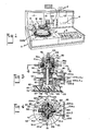
- the turret valve assembly as best seen in FIG. 3, comprises a valve plug member 35 which is of truncated conical shape mounted on the upper end of shaft member 36. It is contemplated that plug member 35 and shaft member 36 may be made in one piece. Plug member 35, as best seen in FIG. 3 is provided with an internal channel 39 which is L-shaped in cross-section formed of connecting channel legs 39a and 39b. Plug member 35 is disposed centrally within a complementary cavity 40 formed in turret housing 41 which is basically of square cross-section as viewed in FIG. 2.
- a coil spring 75 disposed on shaft member 36 has its upper end engaging the underside of plug member 35 and its lower end disposed within retainer nut 77 suitably secured to the shaft member 36, being thus effective to urge the plug member 35 into pressure engagement with the complementary wall of housing cavity 40 and thereby provide a substantially liquid-light relation therebetween.
- a flanged nut 102 formed in its present configuration of a suitable plastic such as nylon, has one end of a flexible tube 103 projecting centrally therethrough and terminating in a flared end 104.
- a plug 105 is slidably disposed over the flared end 104 of said tube and is provided with stem portion 105a of reduced diameter to define annular shoulder 106 upon which seats one end of coil spring 107, the other end of said spring seating within the externally threaded boss 109 of said flanged nut 102.
- the flared end 104 of tube 103 is placed into entry port 47 and engages seat 112 provided at the inner end of said port.
- the coil spring 107 Upon threading the nut 102 into said port, the coil spring 107 provides suitable pressure against said flared end to provide a liquid-tight seal between it and seat 112.
- Buffer fluid is manipulated for aspirating and dispensing by an automatic pipette/dilutor or reversably actuatable syringe of the analyzer which is effective to aspirate diluted serum out of a dilution cup and thence subsequently to dispense said diluted serum and a selected reagent material into a reaction cup carried on turntable or transport T.
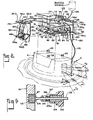
- each said clip is intended to be swung downwardly about its ends to permit the placement of a reagent bottle or the like, as identified at 154, 154a and 154b to capture the bottle between the coupling and the clip.
- a length of tubing 163 has one end attached to one end of a short tube 164, the opposite end of which is connectable to coupling member 146a and communicates via said coupling with the tubing 160.
- the opposite end of tubing 163 is connected to inlet port 42 in the side wall 41b of turret housing 41 preferably by the same termination assembly as previously described to connect the heated buffer material via flexible tube 103 to entry port 47.
- the bottle 154d connecting with the remaining coupling member 146d in housing side wall 41d may be utilized as a waste position for certain test procedures whereby said bottle may alternately be connectable to one of the ports of the valve and positioned to collect the reaction sample at the completion of its analysis.
- the aforementioned encoding plate 54 carried on coupling 50 is provided with four slots, each having a particular configuration as identified at 190-193, respectively, each of said slots being spaced 90° about the perimeter of said plate from its adjacent slot, as best seen im FIG. 4.
- this position is also referred to as the "home position” or “dispenser probe” position in which position, as is more fully described below, the probe C is operable to aspirate the test sample out of a sample cup and dispense said sample and one or more buffer materials into the dilution cup.
- the dispenser probe C is operable to aspirate a predetermined volume of diluted serum out of a dilution cup and thereafter to dispense the diluted serum along with one or more reagent materials serially into a reaction cup.
- Encoding plate slot 191 is of inverted L shape with one leg 191a projecting radially into the plate 54 from its periphery and located 90° from the stem portion of T-shaped slot 190.
- the slot leg 191a connects at its inner end with the other leg 191b which extends perpendicularly and to the left as viewed in FIG. 4.
- Slot 191 is dimensioned such that when it is centred between the plates 200a and 200b of sensor head 200 only sensor pairs 204b, 206b and 204c, 206c are activated and sensor pair 204a, 206a is deactivated.
- the instrument when slot 191 is centred within sensor head 200 the instrument is programmed to provide a suitable antibody enzyme to the probe C preparatory to dispensing the same into a reaction cup.
- Slot 192 is of rectangular configuration being spaced 90° from slot 191 on said plate 54 and projecting radially into the same from its periphery. Slot 192 is dimensioned such that when it is centred within the sensor head 200 both pairs (204a, 206a and 204b, 206b) of the aforesaid sensors are inactivated, while pair 204c, 206c is activated.
- Slot 193 is of reverse L-shaped configuration with one leg 193a projecting radially inwardly into the plate 54 from its periphery, being located clockwise 90° from the rectangular slot 192.
- the slot leg 193a connects at its inner end with the other leg 193b which projects perpendicularly and to the left therefrom.
- Slot 193 is dimensioned such that when it is centred within the sensor head 200 only the sensor pairs 204a, 206a and 204c, 206c are activated, and the instrument is programmed to provide for aspirating a fluorescein drug reagant material preparatory to dispensing the same into a reaction cup.
- the Impact 400 type of instrument is a microprocessor controlled clinical chemistry analyzer in which the operator uses the instrument keyboard to program and preselect the test analysis to be undertaken by said instrument.
- the microprocessor is interconnected with the module in a manner as is understood in the art whereby the buffer heater 118 is connected into the microprocessor circuitry and controlled thereby so as to maintain the dilution liquid material passing therethrough at a temperature in the range of 35°C to 45°C.
- the stepping motor 80 is connected to said instrument control circuitry so as to be periodically actuatable to step the valve plug member 35 and sensor plate 54 selectively to one of its four positions during a sample test procedure.
- the reversable syringe of said instrument is then actuated to aspirate or withdraw a suitable volume of serum, as for example approximately 8 microlitres, from said cup and up into the tubing 176 connecting with valve port 45.
- the probe C moves out over the dilution cup d at said test position 1 whereat the withdrawn serum sample and a suitable quantity of heated dilution material, for example approximately 400 microlitres, from the dilution source are dispensed serially into said dilution cup to provide an approximate 50:1 dilution.
- the probe C is then raised, the stepping motor 80 actuated to rotate the valve plug 35 and encoding plate 90° clockwise as viewed in FIG. 4 whereby the fluorescein drug reagent material in bottle 154b is connected to the valve plug member 35 and upon programmable actuation of the reversible syringe a predetermined volume (for example 20 microlitres) of said reagent material is sucked into tubing 103.
- a predetermined volume for example 20 microlitres
- the turntable transport T is stepped clockwise as viewed in FIG. 2 to bring the last preceding test position 2 under the probe C.
- the probe C is then lowered into the reaction cup r at the test position 2 and concurrently stepping motor is actuated to rotate valve plug 35 and encoding plate 90° counterclockwise.
- the fluorescein drug reagent material is then dispensed into said reaction cup through tubing 103 and 176 along with a predetermined volume of dilution material from said dilution source to begin the incubation period for the diluted test serum sample in said reaction cup of test position 2.
- the probe C is again raised, and the turntable transport T is reversibly stepped counterclockwise as viewed in FIG. 2 to again locate said probe C over test position 1.
- the valve plug member 35 and encoding plate 54 are stepped by the actuation of stepping motor 80 90° counterclockwise as seen in FIGURE 4 to locate encoding slot 191 between the plates of the sensor 200.
- Antibody enzyme in reagent bottle 154c is then drawn by the instrument syringe out of said bottle and into tubing 103.
- valve plug member 35 and encoding plate 54 are then stepped by stepping motor 80 clockwise 90° as viewed in FIG. 4 to return the encoding slot 190 between the plates of the sensor 200 or to the "home position".
- the probe C is then extended into the dilution cup d at test position 1 whereat a predetermined volume of the diluted serum sample in said dilution cup is aspirated or sucked out thereof and into tubing 176.
- the probe C is then extended out over the reaction cup r at said test position 1, the probe lowered into said cup and the diluted serum sample is dispensed into said reaction cup r serially with the antibody-enzyme from tubing 103 and a suitable volume of dilution material.
- the probe C is again raised out of the reaction cup at test position 1 and the turntable transport T is stepped counterclockwise as viewed in FIGURE 2 to locate the probe C at the next test position 0 at which the cycle just described is repeated.
- each reaction cup carrying the sample test mixture i.e. serum sample, dilution material, antibody enzyme and fluorescein reagent material is moved individually by the turntable transport T to the reading station R whereat a predetermined volume of said mixture is aspirated out of said cup and presented to the spectrophotometer of said instrument wherein its absorption and/or fluorescent analysis is undertaken.
- sample test mixture i.e. serum sample, dilution material, antibody enzyme and fluorescein reagent material
- test module or reagent handling device of the present invention relates to a preferred embodiment of test module or reagent handling device of the present invention and the manner in which it is used with a typical clinical analyzer for performing a plurality of biochemistry assays and immunoassays, it will be realized that various modifications may be made within the scope of the invention.
Landscapes
- Physics & Mathematics (AREA)
- Health & Medical Sciences (AREA)
- Life Sciences & Earth Sciences (AREA)
- Chemical & Material Sciences (AREA)
- Analytical Chemistry (AREA)
- Biochemistry (AREA)
- General Health & Medical Sciences (AREA)
- General Physics & Mathematics (AREA)
- Immunology (AREA)
- Pathology (AREA)
- Automatic Analysis And Handling Materials Therefor (AREA)
- Investigating Or Analysing Biological Materials (AREA)
Applications Claiming Priority (2)
| Application Number | Priority Date | Filing Date | Title |
|---|---|---|---|
| US06/405,764 US4737342A (en) | 1982-08-06 | 1982-08-06 | Test module |
| US405764 | 1982-08-06 |
Publications (3)
| Publication Number | Publication Date |
|---|---|
| EP0101192A2 true EP0101192A2 (de) | 1984-02-22 |
| EP0101192A3 EP0101192A3 (en) | 1984-05-23 |
| EP0101192B1 EP0101192B1 (de) | 1987-05-27 |
Family
ID=23605130
Family Applications (1)
| Application Number | Title | Priority Date | Filing Date |
|---|---|---|---|
| EP83304116A Expired EP0101192B1 (de) | 1982-08-06 | 1983-07-15 | Modul für ein klinisches Analysiergerät |
Country Status (4)
| Country | Link |
|---|---|
| US (1) | US4737342A (de) |
| EP (1) | EP0101192B1 (de) |
| JP (1) | JPS5944662A (de) |
| DE (1) | DE3371816D1 (de) |
Cited By (1)
| Publication number | Priority date | Publication date | Assignee | Title |
|---|---|---|---|---|
| EP0286536A1 (de) * | 1987-04-09 | 1988-10-12 | Compagnie Generale Des Matieres Nucleaires (Cogema) | Schrittweise fortschreitende rotierende Transportvorrichtung und mit einer solchen Vorrichtung ausgestattetes Probenentnahmesystem |
Families Citing this family (27)
| Publication number | Priority date | Publication date | Assignee | Title |
|---|---|---|---|---|
| AT391213B (de) * | 1987-05-12 | 1990-09-10 | Avl Verbrennungskraft Messtech | Einrichtung zur wahlweisen beschickung eines analysengeraetes |
| US6436349B1 (en) | 1991-03-04 | 2002-08-20 | Bayer Corporation | Fluid handling apparatus for an automated analyzer |
| US20060013729A1 (en) * | 1991-02-14 | 2006-01-19 | Glen Carey | Fluid handling apparatus for an automated analyzer |
| US6498037B1 (en) * | 1991-03-04 | 2002-12-24 | Bayer Corporation | Method of handling reagents in a random access protocol |
| CA2384519C (en) * | 1991-03-04 | 2006-08-15 | Bayer Corporation | Automated analyzer |
| US5540890A (en) * | 1992-03-27 | 1996-07-30 | Abbott Laboratories | Capped-closure for a container |
| US5376313A (en) * | 1992-03-27 | 1994-12-27 | Abbott Laboratories | Injection molding a plastic assay cuvette having low birefringence |
| US5960160A (en) * | 1992-03-27 | 1999-09-28 | Abbott Laboratories | Liquid heater assembly with a pair temperature controlled electric heating elements and a coiled tube therebetween |
| US5605665A (en) * | 1992-03-27 | 1997-02-25 | Abbott Laboratories | Reaction vessel |
| US5575978A (en) * | 1992-03-27 | 1996-11-19 | Abbott Laboratories | Sample container segment assembly |
| US6190617B1 (en) | 1992-03-27 | 2001-02-20 | Abbott Laboratories | Sample container segment assembly |
| US5627522A (en) * | 1992-03-27 | 1997-05-06 | Abbott Laboratories | Automated liquid level sensing system |
| US5610069A (en) * | 1992-03-27 | 1997-03-11 | Abbott Laboratories | Apparatus and method for washing clinical apparatus |
| US5646049A (en) * | 1992-03-27 | 1997-07-08 | Abbott Laboratories | Scheduling operation of an automated analytical system |
| US5507410A (en) * | 1992-03-27 | 1996-04-16 | Abbott Laboratories | Meia cartridge feeder |
| US5635364A (en) * | 1992-03-27 | 1997-06-03 | Abbott Laboratories | Assay verification control for an automated analytical system |
| US5578494A (en) * | 1992-03-27 | 1996-11-26 | Abbott Laboratories | Cap actuator for opening and closing a container |
| US5536471A (en) * | 1992-03-27 | 1996-07-16 | Abbott Laboratories | Syringe with bubble flushing |
| USD349861S (en) | 1992-07-20 | 1994-08-23 | Abbott Laboratories | Automated analytical instrument |
| JP3786724B2 (ja) * | 1994-08-11 | 2006-06-14 | エスアイアイ・ナノテクノロジー株式会社 | 誘導結合プラズマ分析装置およびその試料導入装置 |
| US5599501A (en) * | 1994-11-10 | 1997-02-04 | Ciba Corning Diagnostics Corp. | Incubation chamber |
| US5856194A (en) | 1996-09-19 | 1999-01-05 | Abbott Laboratories | Method for determination of item of interest in a sample |
| US5795784A (en) | 1996-09-19 | 1998-08-18 | Abbott Laboratories | Method of performing a process for determining an item of interest in a sample |
| US6063634A (en) * | 1998-04-01 | 2000-05-16 | Abbott Laboratories | Fluid assembly and method for diagnostic instrument |
| WO2001006429A1 (en) * | 1999-07-15 | 2001-01-25 | Shea Robert S | Method of sequencing chronic disease testing, reporting and evaluation |
| US7250303B2 (en) * | 2001-07-20 | 2007-07-31 | Ortho-Clinical Diagnostics, Inc. | Chemistry system for a clinical analyzer |
| JP4251627B2 (ja) * | 2003-09-19 | 2009-04-08 | 株式会社東芝 | 化学分析装置及びその分注方法 |
Family Cites Families (14)
| Publication number | Priority date | Publication date | Assignee | Title |
|---|---|---|---|---|
| US3449959A (en) * | 1966-06-27 | 1969-06-17 | Bausch & Lomb | Sample container for automatic sampling apparatus |
| US3536450A (en) * | 1969-06-11 | 1970-10-27 | Univ California | System for analyzing compounds |
| CA950703A (en) * | 1970-04-03 | 1974-07-09 | Manuel C. Sanz | Automatic test tube transporter and sample dispenser |
| US3802782A (en) * | 1970-08-19 | 1974-04-09 | Rohe Scientific Corp | Chemical analyzer performing sequential analysis of samples |
| US3788816A (en) * | 1972-03-02 | 1974-01-29 | Beckman Instruments Inc | Chemical analysis rotary module |
| US3912456A (en) * | 1974-03-04 | 1975-10-14 | Anatronics Corp | Apparatus and method for automatic chemical analysis |
| US3901084A (en) * | 1974-07-19 | 1975-08-26 | Harrison D Brailsford | Vacuum-operated sampler and distributor for multiple sampling operation |
| JPS5916667B2 (ja) * | 1975-02-28 | 1984-04-17 | トウアイヨウデンシ カブシキガイシヤ | 自動血液分析装置 |
| US4058367A (en) * | 1976-05-19 | 1977-11-15 | Gilford Instrument Laboratories Inc. | Automatic asynchronous fluid processing apparatus |
| US4155978A (en) * | 1977-04-27 | 1979-05-22 | Nihon Denshi Kabushiki Kaisha | Automatic chemical analyzer |
| IT1155827B (it) * | 1978-02-15 | 1987-01-28 | Welch Henry H | Apparecchio automatico multicanale per effettuare analisi su fluidi, in particolare analisi chimico-cliniche su liquidi biologici |
| US4156437A (en) * | 1978-02-21 | 1979-05-29 | The Perkin-Elmer Corporation | Computer controllable multi-port valve |
| JPS55144550A (en) * | 1979-04-28 | 1980-11-11 | Olympus Optical Co Ltd | Automatic analyzer |
| US4322216A (en) * | 1981-02-26 | 1982-03-30 | Beckman Instruments, Inc. | Method and apparatus for positioning cars in a sample handling apparatus |
-
1982
- 1982-08-06 US US06/405,764 patent/US4737342A/en not_active Expired - Fee Related
-
1983
- 1983-07-15 DE DE8383304116T patent/DE3371816D1/de not_active Expired
- 1983-07-15 EP EP83304116A patent/EP0101192B1/de not_active Expired
- 1983-08-01 JP JP58139522A patent/JPS5944662A/ja active Pending
Cited By (3)
| Publication number | Priority date | Publication date | Assignee | Title |
|---|---|---|---|---|
| EP0286536A1 (de) * | 1987-04-09 | 1988-10-12 | Compagnie Generale Des Matieres Nucleaires (Cogema) | Schrittweise fortschreitende rotierende Transportvorrichtung und mit einer solchen Vorrichtung ausgestattetes Probenentnahmesystem |
| FR2613704A1 (fr) * | 1987-04-09 | 1988-10-14 | Cogema | Transporteur rotatif a avance pas a pas et installation de prelevement d'echantillons liquides comportant un tel transporteur |
| US4854355A (en) * | 1987-04-09 | 1989-08-08 | Cogema-Compagnie Generale Des Matieres Nucleaires | Stepwise advancing rotary conveyor and installation for taking liquid samples incorporating such a conveyor |
Also Published As
| Publication number | Publication date |
|---|---|
| EP0101192B1 (de) | 1987-05-27 |
| EP0101192A3 (en) | 1984-05-23 |
| DE3371816D1 (en) | 1987-07-02 |
| US4737342A (en) | 1988-04-12 |
| JPS5944662A (ja) | 1984-03-13 |
Similar Documents
| Publication | Publication Date | Title |
|---|---|---|
| EP0101192B1 (de) | Modul für ein klinisches Analysiergerät | |
| US7855084B2 (en) | Chemistry system for clinical analyzer | |
| US4933147A (en) | Unitized reagent containment system for clinical analyzer | |
| JP3214895B2 (ja) | 免疫学的検定用試薬パック | |
| CA1335345C (en) | Test card for performing assays | |
| KR100920652B1 (ko) | 생화학 측정기를 위한 계량 시스템의 자동 정렬 방법 | |
| JP3677298B2 (ja) | 自動化学分析装置 | |
| CA1296403C (en) | Automated patient sample analysis instrument | |
| AU636568B2 (en) | Reaction cartridge and carousel for biological sample analyzer | |
| CA1335383C (en) | Apparatus and method for providing assay calibration data | |
| US4346056A (en) | Automatic analyzing apparatus | |
| EP1906187B1 (de) | Zusatz-Zuführsystem für Proben in einem klinischen Analysegerät | |
| CN106226541B (zh) | 一种新型低交叉污染的全自动生化分析仪 | |
| US6299839B1 (en) | System and methods for performing rotor assays | |
| AU596799B2 (en) | Unitized reagent containment system for clinical analyzer | |
| JP2008532048A (ja) | 自動分析器 | |
| AU636571B2 (en) | Biological sample analyzer | |
| EP0336309A2 (de) | Analysegerät zur Durchführung klinisch-chemischer Analysen und immunologischer Tests mit selektivem oder sequentiellem Zugriff | |
| JPH03285168A (ja) | 試料分注装置 |
Legal Events
| Date | Code | Title | Description |
|---|---|---|---|
| PUAI | Public reference made under article 153(3) epc to a published international application that has entered the european phase |
Free format text: ORIGINAL CODE: 0009012 |
|
| AK | Designated contracting states |
Designated state(s): DE FR GB |
|
| PUAL | Search report despatched |
Free format text: ORIGINAL CODE: 0009013 |
|
| AK | Designated contracting states |
Designated state(s): DE FR GB |
|
| 17P | Request for examination filed |
Effective date: 19841018 |
|
| 17Q | First examination report despatched |
Effective date: 19860320 |
|
| GRAA | (expected) grant |
Free format text: ORIGINAL CODE: 0009210 |
|
| AK | Designated contracting states |
Kind code of ref document: B1 Designated state(s): DE FR GB |
|
| REF | Corresponds to: |
Ref document number: 3371816 Country of ref document: DE Date of ref document: 19870702 |
|
| ET | Fr: translation filed | ||
| PLBE | No opposition filed within time limit |
Free format text: ORIGINAL CODE: 0009261 |
|
| STAA | Information on the status of an ep patent application or granted ep patent |
Free format text: STATUS: NO OPPOSITION FILED WITHIN TIME LIMIT |
|
| 26N | No opposition filed | ||
| PGFP | Annual fee paid to national office [announced via postgrant information from national office to epo] |
Ref country code: GB Payment date: 19890630 Year of fee payment: 7 |
|
| PGFP | Annual fee paid to national office [announced via postgrant information from national office to epo] |
Ref country code: FR Payment date: 19890719 Year of fee payment: 7 |
|
| PGFP | Annual fee paid to national office [announced via postgrant information from national office to epo] |
Ref country code: DE Payment date: 19890727 Year of fee payment: 7 |
|
| PG25 | Lapsed in a contracting state [announced via postgrant information from national office to epo] |
Ref country code: GB Effective date: 19900715 |
|
| GBPC | Gb: european patent ceased through non-payment of renewal fee | ||
| PG25 | Lapsed in a contracting state [announced via postgrant information from national office to epo] |
Ref country code: FR Effective date: 19910329 |
|
| PG25 | Lapsed in a contracting state [announced via postgrant information from national office to epo] |
Ref country code: DE Effective date: 19910403 |
|
| REG | Reference to a national code |
Ref country code: FR Ref legal event code: ST |