EP0100702B1 - Igniting device for oxygen cutting lances - Google Patents
Igniting device for oxygen cutting lances Download PDFInfo
- Publication number
- EP0100702B1 EP0100702B1 EP83401353A EP83401353A EP0100702B1 EP 0100702 B1 EP0100702 B1 EP 0100702B1 EP 83401353 A EP83401353 A EP 83401353A EP 83401353 A EP83401353 A EP 83401353A EP 0100702 B1 EP0100702 B1 EP 0100702B1
- Authority
- EP
- European Patent Office
- Prior art keywords
- reservoir
- lance
- container
- synthetic material
- oxygen
- Prior art date
- Legal status (The legal status is an assumption and is not a legal conclusion. Google has not performed a legal analysis and makes no representation as to the accuracy of the status listed.)
- Expired
Links
- QVGXLLKOCUKJST-UHFFFAOYSA-N atomic oxygen Chemical compound [O] QVGXLLKOCUKJST-UHFFFAOYSA-N 0.000 title claims abstract description 84
- 239000001301 oxygen Substances 0.000 title claims abstract description 84
- 229910052760 oxygen Inorganic materials 0.000 title claims abstract description 84
- 150000001875 compounds Chemical class 0.000 claims abstract description 32
- 239000000446 fuel Substances 0.000 claims abstract description 6
- 229920002994 synthetic fiber Polymers 0.000 claims description 26
- 230000001590 oxidative effect Effects 0.000 claims description 13
- 239000000843 powder Substances 0.000 claims description 10
- LYCAIKOWRPUZTN-UHFFFAOYSA-N Ethylene glycol Chemical compound OCCO LYCAIKOWRPUZTN-UHFFFAOYSA-N 0.000 claims description 9
- 239000003054 catalyst Substances 0.000 claims description 7
- 238000002485 combustion reaction Methods 0.000 claims description 7
- 229920005862 polyol Polymers 0.000 claims description 3
- 150000003077 polyols Chemical class 0.000 claims description 3
- 239000012286 potassium permanganate Substances 0.000 claims description 3
- 239000007800 oxidant agent Substances 0.000 claims description 2
- 229910052788 barium Inorganic materials 0.000 claims 1
- DSAJWYNOEDNPEQ-UHFFFAOYSA-N barium atom Chemical group [Ba] DSAJWYNOEDNPEQ-UHFFFAOYSA-N 0.000 claims 1
- 230000001737 promoting effect Effects 0.000 claims 1
- ZZUFCTLCJUWOSV-UHFFFAOYSA-N furosemide Chemical compound C1=C(Cl)C(S(=O)(=O)N)=CC(C(O)=O)=C1NCC1=CC=CO1 ZZUFCTLCJUWOSV-UHFFFAOYSA-N 0.000 description 11
- XEEYBQQBJWHFJM-UHFFFAOYSA-N Iron Chemical compound [Fe] XEEYBQQBJWHFJM-UHFFFAOYSA-N 0.000 description 8
- 238000007789 sealing Methods 0.000 description 8
- 239000007788 liquid Substances 0.000 description 7
- 238000000034 method Methods 0.000 description 7
- 229910052742 iron Inorganic materials 0.000 description 4
- 238000009527 percussion Methods 0.000 description 4
- XLYOFNOQVPJJNP-UHFFFAOYSA-N water Substances O XLYOFNOQVPJJNP-UHFFFAOYSA-N 0.000 description 4
- 229940125810 compound 20 Drugs 0.000 description 3
- 229940126540 compound 41 Drugs 0.000 description 3
- 238000006073 displacement reaction Methods 0.000 description 3
- PEDCQBHIVMGVHV-UHFFFAOYSA-N Glycerine Chemical compound OCC(O)CO PEDCQBHIVMGVHV-UHFFFAOYSA-N 0.000 description 2
- 206010061218 Inflammation Diseases 0.000 description 2
- 229910000831 Steel Inorganic materials 0.000 description 2
- 239000000853 adhesive Substances 0.000 description 2
- 238000004026 adhesive bonding Methods 0.000 description 2
- 230000001070 adhesive effect Effects 0.000 description 2
- ZJRXSAYFZMGQFP-UHFFFAOYSA-N barium peroxide Chemical group [Ba+2].[O-][O-] ZJRXSAYFZMGQFP-UHFFFAOYSA-N 0.000 description 2
- 238000006243 chemical reaction Methods 0.000 description 2
- HQWPLXHWEZZGKY-UHFFFAOYSA-N diethylzinc Chemical compound CC[Zn]CC HQWPLXHWEZZGKY-UHFFFAOYSA-N 0.000 description 2
- 230000004927 fusion Effects 0.000 description 2
- 239000007789 gas Substances 0.000 description 2
- 230000004054 inflammatory process Effects 0.000 description 2
- 239000010959 steel Substances 0.000 description 2
- 239000000126 substance Substances 0.000 description 2
- SBASXUCJHJRPEV-UHFFFAOYSA-N 2-(2-methoxyethoxy)ethanol Chemical compound COCCOCCO SBASXUCJHJRPEV-UHFFFAOYSA-N 0.000 description 1
- ZNQVEEAIQZEUHB-UHFFFAOYSA-N 2-ethoxyethanol Chemical compound CCOCCO ZNQVEEAIQZEUHB-UHFFFAOYSA-N 0.000 description 1
- DOPZLYNWNJHAOS-UHFFFAOYSA-N 2-methyl-1,2-butanediol Chemical compound CCC(C)(O)CO DOPZLYNWNJHAOS-UHFFFAOYSA-N 0.000 description 1
- 208000031968 Cadaver Diseases 0.000 description 1
- FYYHWMGAXLPEAU-UHFFFAOYSA-N Magnesium Chemical compound [Mg] FYYHWMGAXLPEAU-UHFFFAOYSA-N 0.000 description 1
- 239000003610 charcoal Substances 0.000 description 1
- 230000006835 compression Effects 0.000 description 1
- 238000007906 compression Methods 0.000 description 1
- 230000003247 decreasing effect Effects 0.000 description 1
- XXJWXESWEXIICW-UHFFFAOYSA-N diethylene glycol monoethyl ether Chemical compound CCOCCOCCO XXJWXESWEXIICW-UHFFFAOYSA-N 0.000 description 1
- 229940075557 diethylene glycol monoethyl ether Drugs 0.000 description 1
- 238000009792 diffusion process Methods 0.000 description 1
- 230000000694 effects Effects 0.000 description 1
- 229920001971 elastomer Polymers 0.000 description 1
- 239000000806 elastomer Substances 0.000 description 1
- -1 ethylene glycol Chemical class 0.000 description 1
- 235000011187 glycerol Nutrition 0.000 description 1
- 238000010438 heat treatment Methods 0.000 description 1
- 229910052749 magnesium Inorganic materials 0.000 description 1
- 239000011777 magnesium Substances 0.000 description 1
- 229910052751 metal Inorganic materials 0.000 description 1
- 239000002184 metal Substances 0.000 description 1
- 150000002739 metals Chemical class 0.000 description 1
- 239000002245 particle Substances 0.000 description 1
- 230000035515 penetration Effects 0.000 description 1
- 230000002093 peripheral effect Effects 0.000 description 1
- 239000011150 reinforced concrete Substances 0.000 description 1
- 238000011160 research Methods 0.000 description 1
- 239000011435 rock Substances 0.000 description 1
- 238000010008 shearing Methods 0.000 description 1
- 239000007787 solid Substances 0.000 description 1
- 239000010902 straw Substances 0.000 description 1
- 210000002268 wool Anatomy 0.000 description 1
Images

Classifications
-
- B—PERFORMING OPERATIONS; TRANSPORTING
- B23—MACHINE TOOLS; METAL-WORKING NOT OTHERWISE PROVIDED FOR
- B23K—SOLDERING OR UNSOLDERING; WELDING; CLADDING OR PLATING BY SOLDERING OR WELDING; CUTTING BY APPLYING HEAT LOCALLY, e.g. FLAME CUTTING; WORKING BY LASER BEAM
- B23K7/00—Cutting, scarfing, or desurfacing by applying flames
- B23K7/10—Auxiliary devices, e.g. for guiding or supporting the torch
-
- B—PERFORMING OPERATIONS; TRANSPORTING
- B23—MACHINE TOOLS; METAL-WORKING NOT OTHERWISE PROVIDED FOR
- B23K—SOLDERING OR UNSOLDERING; WELDING; CLADDING OR PLATING BY SOLDERING OR WELDING; CUTTING BY APPLYING HEAT LOCALLY, e.g. FLAME CUTTING; WORKING BY LASER BEAM
- B23K7/00—Cutting, scarfing, or desurfacing by applying flames
- B23K7/08—Cutting, scarfing, or desurfacing by applying flames by applying additional compounds or means favouring the cutting, scarfing, or desurfacing procedure
-
- E—FIXED CONSTRUCTIONS
- E21—EARTH OR ROCK DRILLING; MINING
- E21B—EARTH OR ROCK DRILLING; OBTAINING OIL, GAS, WATER, SOLUBLE OR MELTABLE MATERIALS OR A SLURRY OF MINERALS FROM WELLS
- E21B7/00—Special methods or apparatus for drilling
- E21B7/14—Drilling by use of heat, e.g. flame drilling
- E21B7/143—Drilling by use of heat, e.g. flame drilling underwater
-
- E—FIXED CONSTRUCTIONS
- E21—EARTH OR ROCK DRILLING; MINING
- E21B—EARTH OR ROCK DRILLING; OBTAINING OIL, GAS, WATER, SOLUBLE OR MELTABLE MATERIALS OR A SLURRY OF MINERALS FROM WELLS
- E21B7/00—Special methods or apparatus for drilling
- E21B7/14—Drilling by use of heat, e.g. flame drilling
- E21B7/146—Thermal lances
Definitions
- the present invention relates to the ignition of oxygen lances.
- the present invention relates more precisely to an improved device for the ignition of oxygen lances.
- the oxygen lances consist of a steel or iron tube, partially filled with solid steel or iron wires or rods, fitted into the lance.
- Oxygen is supplied to the lance at one end of the lance, so a jet of pressurized oxygen carried inside the tube is brought to the other end of the tube on an object which one wishes for example to pierce or cut, the combustion of the tube and rods in oxygen releasing a quantity of heat, used for example to cause the fusion of metals, reinforced concrete or not, and rocks, especially underwater.
- the fusion products are expelled by the oxygen jet.
- the ignition of the oxygen lances was carried out, originally by heating the lance at its front end, located near the object to be worked, using, for example, an oxyhydric torch, at the same time as 'Oxygen is brought to the level of said end of the tube.
- an oxyhydric torch it is known to light the oxygen lances, by bringing the end of these in contact with glowing charcoal or embers.
- an ignition process is inconvenient to implement and relatively long. This process cannot therefore be satisfactory, especially when the oxygen lance must be lit relatively often.
- such a process requires, when it is to be carried out under water, the use of an electrode or a special torch.
- the present invention comes to propose a new device for igniting an oxygen lance, of the type formed by a body having one end capable of opening to be threaded onto the end of the lance and which comprises a combustible element and means capable of causing, 'ignition of the fuel element;
- the device according to the present invention more specifically comprises a container housed axially in the body and closed in leaktight manner at its two ends, to contain a first chemical compound, a sealed reservoir containing a second chemical compound capable of reacting with the first, in producing an inflammation, when it comes into contact therewith, and a perforating member capable of axial translation relative to the container and / or reservoir and capable of perforating a wall of the container and of said sealed reservoir, in order to bring into contact the first and second chemical compounds, during displacement, and in particular when the oxygen lance
- one of the chemical compounds is an oxidant; and more precisely the first chemical compound is an oxidizing powder.
- the container or tank further contain a catalyst to promote the combustion of said chemical compounds and accelerate the ignition of the oxygen lance.
- the container is closed, on the side opposite the end of the body by which the lance is engaged, by a cape of synthetic material, which also closes the corresponding end of the body, on the other side , by a disc integral with the perforating member, the latter having a portion which extends axially in the container and ends in a bevel in the vicinity of said cape of synthetic material.
- the reservoir consists of a separate member adapted to be screwed onto the body facing the cape of synthetic material, and the adjacent end of the reservoir, in the assembled position, to this cape in synthetic material, consists of a plastic cap preferably provided with a cutting primer.
- the perforation member constitutes a perforation piston displaceable in the body.
- the reservoir is produced in the body, opposite the opening-capable end and is closed, on the interior side of the body, by a plastic cap, while the container is mounted movable. in the body and is closed by a plastic cap at its end adjacent to the tank, and that the perforating member is carried fixed in the tank.
- the oxidizing chemical compound is preferably potassium permanganate.
- the catalyst is preferably barium dioxide.
- the second chemical compound is preferably a polyol, such as ethylene glycol.
- the end of the body through which the oxygen lance is introduced is initially closed using a removable waterproof plug.
- the end of the body by which the oxygen lance is introduced is provided with a lance fixing ring whose internal diameter is adapted to the external diameter of the lance.
- the device for igniting an oxygen lance consists of a generally cylindrical body 10, initially closed at one of its ends, by which the lance oxygen 100 is intended to be introduced, using a removable obturator referenced 80, the body 10 being closed at its other end, at which it is intended to receive a reservoir 40 (as shown in the Figure 1), by a cape of synthetic material.
- the body 10 consists of a generally cylindrical envelope 11 having an internal diameter greater than the external diameter of the oxygen lances 100 with which the device is intended to cooperate, such so that the envelope 11 is threaded on the end of these.
- the envelope 11 is threaded on the end of these.
- the axis of the cylindrical envelope has been referenced 0-0 in FIG. 1.
- the cylindrical envelope 11 has on its outer periphery, on the side of the end by which the oxygen lances 100 are intended to be introduced, an annular rib 12 intended to receive a removable shutter 80 as will be described in more detail in the continuation of the description.
- the cylindrical casing 11 is extended by a coaxial cylindrical section 13, of smaller diameter, internally threaded.
- annular rib 14 serving as a bearing surface for the cape of synthetic material 70, as appears on the Figure 1.
- an inner cylindrical jacket 15 which is coaxial with it, and which is connected to the latter at the level of the annu laire 14 above.
- Said inner cylindrical jacket 15 has a length substantially equal to half that of the cylindrical envelope 11.
- a cap made of synthetic material 70 in the form of a bowl, is arranged in the bottom of said inner cylindrical jacket 15, bearing against the annular rib 14. More precisely, the cap 70 made of synthetic material bowl-shaped, consists of a disc 71, which bears against said annular rib 14, and a cylindrical rim 72, projecting perpendicularly on this disc, and whose outer surface is supported on the inner periphery of the inner cylindrical liner 15, matching the shape thereof. It will be understood that thus said cape of synthetic material 70 sealingly seals one of the ends of the cylindrical jacket 15.
- the perforation piston 50 consists of a disc 51 perpendicular to the axis 0-0, of the body 10 of the device.
- the disc 51 has an outside diameter substantially equal to the inside diameter of the cylindrical jacket 15.
- the disc 51 is provided on its periphery with a cylinder 52 which comes into sealing contact against the internal peripheral surface of the cylindrical jacket 15.
- the disc 51 of the perforating piston 50 is disposed inside the jacket 15, opposite the cap of the aforementioned synthetic material 70, so that it is defined, inside the cylindrical jacket 15 , and between the cape of synthetic material 70 and the disc 51, a perfectly sealed container or volume intended to contain a first chemical compound 20 schematically represented in FIG. 1.
- the disc 51 of the perforating piston 50 is provided on the side of the annular rib 12, with a hollow cylindrical section 53, of smaller diameter, coaxial with the axis 0-0 of the device and on the end of which is intended to come in support the oxygen lance 100, as shown in Figure 1.
- the disc 51 of the perforating piston 50 is provided with a second section 54 also cylindrical and of smaller diameter and coaxial with the axis 0-0 of the device, and which ends in a bevel.
- this section 54 is provided with a plurality of orifices provided in its wall, intended to subsequently facilitate the bringing into contact of the first and second chemical compounds.
- the length of this section 54 is determined so that, in the storage position, as shown in FIG. 1, the beveled end of this section 54 is located in the vicinity of said plastic cap 70, without to be in contact with it.
- the cylinder 52 disposed on the outside of the disc 51 of the perforating piston 50 is preferably provided with four lugs 55, projecting outwards, and regularly distributed around its periphery , on the side of the first section 53.
- the four pins 55 are intended to come into abutment against the end of the inner cylindrical jacket 15, so as to prevent in the storage position, for example during an accidental fall, penetration of the perforating piston 50, inside said jacket 15, which would inevitably cause the perforation of the cap of synthetic material 70, thanks to the beveled end of the second section 54 of the piston, and thereby flow of the chemical compound 20 contained in the jacket 15.
- the body 10 containing a first chemical compound, and the reservoir 40 containing a second chemical compound 41 capable of reacting with the first producing an inflammation, when it comes into contact with the latter are stored separately. There is thus shown in Figure 4, the separate tank 40.
- the reservoir 40 consists of a hollow cylindrical plug. More precisely, the hollow cylindrical plug 40 consists of a disc wall 42, and a cylindrical wall connected perpendicularly thereto. This cylindrical wall has, on the side opposite to the discoid wall 42, a section 43 of smaller diameter, externally threaded. In addition, this same section 43 is internally threaded over a part of its length, so that a cap 44 made of synthetic material can be screwed onto the reservoir 40, at the level of the internal thread thereof, so as to thus define a sealed volume or tank containing the second chemical compound 41.
- the assembly of the reservoir 40 on the body 10, and of the plastic cap 44 on the reservoir 40 can be done by any other suitable conventional means.
- the plastic plug 44 assembled on the reservoir 40 is provided with a cutting primer.
- the envelope 11 is provided with an oxygen passage orifice 16 which is initially blocked with the aid of an adhesive sealing disc 17 placed on the outside of the cylindrical casing 11.
- the cylindrical envelope 11 is closed off, initially on the side of the annular rib 12, using a flexible sleeve 81 fitted with a sealing plug 82.
- the flexible sleeve 81 consists of a crown 83 connected to a cylindrical skirt 84, which itself extends by a frustoconical skirt 85, the latter narrowing away from the crown 83.
- this crown 83 is provided, on its outer periphery with a flange 86 which is intended (as shown in Figure 2) to overlap the annular rib 12 provided on the envelope cylindrical loppe 11, so as to immobilize the flexible sleeve 81 thereon.
- the sealing plug 82 is composed of a disc wall 87, extended by a cylindrical wall 88 having an outside diameter substantially greater than the inside diameter of the above-mentioned cylindrical skirt 84.
- the device according to the present invention can cooperate with oxygen lances 100 having different diameters.
- FIG. 3 Another embodiment of the shutter 80 is shown in FIG. 3.
- the shutter consists of a crown 93 connected to a cylindrical skirt 94, itself connected opposite the crown 93, two cylindrical skirts 95 and 96 of decreasing diameter.
- the cylindrical skirt 96 of smaller diameter is closed at its end opposite to the crown 93, by a discoid transverse end wall 97.
- the crown 93 of the shutter shown in the Figure 3 is provided on its outer periphery with a flange 98 intended to overlap the annular rib 12 provided on the cylindrical casing 11, to ensure the immobilization of the shutter 80 on the body 10 of the device.
- all of the components of the device according to the present invention are made of synthetic materials, so that these can be consumed at least partially when the oxygen lance is ignited.
- the mechanical and thermal characteristics of the flexible sleeve 81 shown in Figure 2, or of the shutter 80 shown in Figure 3, are preferably determined so that it maintains the ignition device on the end of the oxygen lamp 100 for about twenty seconds, and this for an oxygen inlet pressure of the order of 8 bars.
- the first chemical compound 20 contained in the cylindrical jacket 15 is preferably an oxidizing powder
- the second chemical compound 41 contained in the reservoir 40 is a reactive liquid capable of reacting with said oxidizing powder 20.
- the oxidizing powder 20 is formed of potassium permanganate
- the reactive liquid 41 is a polyol, such as ethylene glycol, or any other similar product such as glycerin , or methylethylethyleneglycol or diethylene glycol monoethyl ether or diethylene glycol monomethyl ether or ethoxyethanol
- the catalyst is barium dioxide, housed with the reactive liquid inside the tank 40.
- the arrangement of the oxidizing powder and the reactive liquid can be reversed, and likewise, the catalyst can be stored with the oxidizing powder and not just with the reactive liquid.
- the oxygen lance 100 is then introduced into the flexible sleeve 81 after removal of the sealing plug 82 (FIG. 2) or into the obturator after cutting of the latter (FIG. 3), depending on the embodiment adopted. As shown in Figure 1, the end of the oxygen lance 100 is thus brought into contact with the first section 53 of the perforating piston 50. Safety, during the introduction of the lance is ensured using four lugs 55, arranged on the periphery of the perforating piston 50. The oxygen supply is then opened, and the pressure adjusted to around 1.5 bar.
- a device for igniting an oxygen lance in accordance with the present invention made it possible to ensure ignition in a few seconds, instead of a few minutes as was the case with the devices previously existing.
- the orifice 16 of the oxygen passage allows the exhaust of gases brought to high temperature.
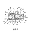
- the device for igniting an oxygen lance consists of a generally cylindrical body 110, the envelope 111 of which has two coaxial sections 112 and 113.
- the first section 112 through one end of which is intended to be introduced the oxygen lance (not shown in FIG. 6) is provided with an orifice 116 for passage of oxygen, which is initially obstructed using an adhesive sealing disc 117 placed on the outside of the cylindrical envelope 111.
- Said first section 112 extends opposite its end by which the oxygen lance is introduced, by a second section 113 of smaller diameter. This last section 113 is closed, opposite the first section 112 by a transverse wall 114 of generally discoid shape.
- said second section 113 and the wall 114 above delimit in combination with a plug 144 preferably made of synthetic material, said sealed reservoir 140 capable of containing the second chemical compound 141.
- the plug 144 consists of a disc wall 145, which extends substantially perpendicular to the longitudinal axis 0-0 of the device, and of a cylindrical wall 146, connected perpendicularly to the wall 145. Said wall 146 extends opposite the reservoir 140, and is applied tightly against the internal wall of the second section 113 of the casing 111, so as to seal said reservoir 140.
- the wall 145 of the plug 144 is provided with a cutting primer.
- a perforation member 150 forming a body with the aforementioned transverse wall 114, is connected perpendicularly to the latter.
- the fixed perforation member 150 consists of a cylindrical element coaxial with the ignition device, and which ends in a bevel at its free end, in the vicinity of the plug 144, without however being in contact with this one.
- the container 115 intended to contain the first chemical compound 120 consists of a cylindrical envelope of axis 0-0 closed at one of its ends (opposite to the reservoir 140) by a discoid transverse wall 118, forming a body therewith. Said container 115 is closed, at its end adjacent to the reservoir 140, by a cap of synthetic material 170, tightly connected to the envelope of the container 115 by any suitable means. As shown in Figure 6, the cap 170 can be connected to the container 115 by gluing.
- said cap 170 can also be connected to the container 115 by any other means such as by threading.
- the container 115 is associated with a system of stops 160.
- such a system of stops 160 may consist of a discoid transverse wall 161, to which a cylindrical section 162 is connected perpendicularly.
- the discoid wall 161 is provided on its outer periphery with a plurality of lugs 163 regularly distributed over its periphery.
- the pins 163 are intended to come into abutment against a radial surface formed on the internal periphery of the first section 112 of the casing 111, and directed towards the end of the latter by which the oxygen lance is intended to be introduced .
- the wall 161 is provided with orifices allowing the passage of gases.
- the container 115 being introduced into the cylindrical section 162 in contact with the discoid wall 161, and immobilized in this position by any appropriate means, such as by gluing or force fitting, it is understood that the pins 163 limit the translation of the container 115 inside the body 110, so as to prevent the cap 170 from coming unintentionally into contact with the plug 144.
- the system of stops 160 and the container 115 can be made up of a single block, the lugs 163 being formed directly on the container 115.
- the stop system 160 may consist of two rectilinear ribs, connected perpendicularly to each other and having at their ends said pins 163, as well as axial extensions, such as the elements 162 shown in FIG. 6. Again , the container 115 is intended to be introduced between the extensions 162, until it comes into contact
- the body 110 is provided on its outer periphery, at its end through which is intended to be introduced the oxygen lance, an external thread 119 adapted to receive a closure plug 185.
- said closure plug 185 consists of a crown 186 to which is connected perpendicularly, a cylindrical section 187 provided with an internal thread 188 capable of cooperating with the above-mentioned external thread 119 of the casing 111.
- the purpose of the closure plug 185 is to immobilize, between its crown 186 and the extreme radial surface of the envelope 111, a ring 193 for fixing the oxygen lance 100, the internal diameter is adapted to the external diameter of the oxygen lance 100 so as to immobilize it correctly.
- Such a fixing ring 193 can be produced for example from elastomers.
- the container 115 is stored separately from the body 110 containing the reservoir 140 filled with the second chemical compound 141.
- the envelope 111 of the body 110 can be closed initially by a shutter similar to the shutter 80 described with reference to FIGS. 1 to 3.
- the container 115 should be introduced inside the envelope 111, until the above-mentioned lugs 163 come to bear against the radial surface provided for this purpose on the internal periphery of the first section 112.
- a fixing ring 193, the diameter of which is adapted to the outside diameter of the oxygen lance 100 is then fixed to the envelope 111 by means of the closure plug 185.
- the oxygen lance is introduced into the envelope 111, in contact with the container 115. Safety, during the introduction of the lance is ensured by the pins 163.
- the oxygen supply is open and the pressure adjusted appropriately.
- the plug 144 and the cap 170 being perforated, the two chemical compounds react with each other and cause the ignition of the lance.
- the reservoir 140 is not completely filled, so that the initial compression of the air contained therein allows the displacement of the plug 144.
- the Applicant has found that when using such a device, the reactive liquid preferably contained in the reservoir 140 is subjected to a significant pressure, during percussion of the oxygen lance, which promotes its diffusion towards the oxidizing powder, and appreciably accelerates the reaction.
- all of the elements making up the device will be made of synthetic material, so that these can be consumed at least partially when the oxygen lance 100 is ignited.
Landscapes
- Engineering & Computer Science (AREA)
- Life Sciences & Earth Sciences (AREA)
- Geology (AREA)
- Mining & Mineral Resources (AREA)
- Physics & Mathematics (AREA)
- Environmental & Geological Engineering (AREA)
- Fluid Mechanics (AREA)
- General Life Sciences & Earth Sciences (AREA)
- Geochemistry & Mineralogy (AREA)
- Mechanical Engineering (AREA)
- Oxygen, Ozone, And Oxides In General (AREA)
- Scissors And Nippers (AREA)
Abstract
Description
La présente invention concerne l'allumage des lances à oxygène.The present invention relates to the ignition of oxygen lances.
La présente invention concerne plus précisément un dispositif perfectionné pour l'allumage des lances à oxygène.The present invention relates more precisely to an improved device for the ignition of oxygen lances.
De façon classique en soi, les lances à oxygène sont constituées par un tube en acier ou en fer, rempli partiellement de fils ou joncs pleins en acier ou en fer, emmanchés dans la lance. L'alimentation en oxygène de la lance, est effectuée au niveau d'une extrémité de celle-ci, ainsi un jet d'oxygène sous pression, véhicule à l'intérieur du tube est amené au niveau de l'autre extrémité du tube sur un objet que l'on désire par exemple percer ou couper, la combustion du tube et des joncs dans l'oxygène dégageant une quantité de chaleur, utilisée par exemple pour provoquer la fusion de métaux, de béton armé ou non, et de roches, notamment sous l'eau. Les produits de la fusion sont chassés par le jet d'oxygène.In a conventional manner in itself, the oxygen lances consist of a steel or iron tube, partially filled with solid steel or iron wires or rods, fitted into the lance. Oxygen is supplied to the lance at one end of the lance, so a jet of pressurized oxygen carried inside the tube is brought to the other end of the tube on an object which one wishes for example to pierce or cut, the combustion of the tube and rods in oxygen releasing a quantity of heat, used for example to cause the fusion of metals, reinforced concrete or not, and rocks, especially underwater. The fusion products are expelled by the oxygen jet.
L'allumage des lances à oxygène était effectué, à l'origine en chauffant la lance à son extrémité avant, située près de l'objet à travailler, à l'aide, par exemple, d'un chalumeau oxhydrique, en même temps qu'on fait arriver de l'oxygène au niveau de ladite extrémité du tube. De façon analogue, on sait allumer les lances à oxygène, en portant l'extrémité de celles-ci en contact avec du charbon de bois incandescent ou de la braise de bois. Il s'avère toutefois qu'un tel procédé d'allumage est incommode à mettre en oeuvre et relativement long. Ce procédé ne peut donc donner satisfaction, surtout lorsque la lance à oxygène doit être allumée relativement souvent. En outre, un tel procédé exige, lorsqu'il doit être mis en oeuvre sous l'eau, l'emploi d'une électrode ou d'un chalumeau spécial.The ignition of the oxygen lances was carried out, originally by heating the lance at its front end, located near the object to be worked, using, for example, an oxyhydric torch, at the same time as 'Oxygen is brought to the level of said end of the tube. In a similar way, it is known to light the oxygen lances, by bringing the end of these in contact with glowing charcoal or embers. However, it turns out that such an ignition process is inconvenient to implement and relatively long. This process cannot therefore be satisfactory, especially when the oxygen lance must be lit relatively often. In addition, such a process requires, when it is to be carried out under water, the use of an electrode or a special torch.
Comme cela est décrit dans le brevet Français n° 1 002 142, on a déjà proposé un dispositif allumeur pour lances à oxygène, formant une cartouche d'allumage par percussion qui comprend une cartouche centrale d'allumage mise à feu lors de la percussion d'un chapeau formant percuteur, ladite cartouche centrale d'allumage communicant le feu à un bourrage en paille de fer qui entoure la cartouche. Le courant d'oxygène amené par le tube active fortement la combustion de la paille de fer. Le dispositif décrit dans ce brevet a permis de simplifier très notablement le procédé antérieurement existant. Toutefois, il s'avère dans la pratique, que ce procédé ne donne pas pleinement satisfaction, en raison du fait notamment que l'allumage de la lance à oxygène reste trop lent. Un dispositif généralement similaire est défini dans le brevet GB-A-668 393.As described in French Patent No. 1,002,142, an igniter device for oxygen lances has already been proposed, forming a percussion ignition cartridge which comprises a central ignition cartridge ignited during percussion of a cap forming a striker, said central ignition cartridge communicating the fire to an iron straw stuffing which surrounds the cartridge. The oxygen current supplied by the tube strongly activates the combustion of the iron wool. The device described in this patent has made it possible to greatly simplify the previously existing process. However, it turns out in practice that this method is not entirely satisfactory, due in particular to the fact that the ignition of the oxygen lance remains too slow. A generally similar device is defined in patent GB-A-668,393.
Comme cela est décrit dans le brevet Français n° 2 348 900, on a proposé un autre procédé d'allumage de lances à oxygène, consistant à amener l'extrémité de la lance en contact avec un élément en combustion formé de particules de magnésium. Ce procédé permet certes d'effectuer l'allumage rapide des lances à oxygène, cependant il s'avère relativement compliqué à mettre en oeuvre, et ne peut être utilisé en aucune façon sous l'eau.As described in French Patent No. 2,348,900, another method of igniting oxygen lances has been proposed, consisting in bringing the end of the lance into contact with a burning element formed of magnesium particles. This process certainly allows for rapid ignition of oxygen lances, however it is relatively complicated to implement, and can not be used in any way underwater.
Enfin, comme cela est décrit dans la demande de brevet Européen publiée sous le n° 7 289 on a proposé différents autres types de cartouches pour l'allumage d'une lance à oxygène. En particulier, comme cela est représenté sur la figure 3 de cette demande de brevet, on a proposé de disposer à l'intérieur du corps d'une cartouche, une amorce comprenant un élément constitué par une substance qui s'enflamme spontanément en présence d'oxygène, telle que du zinc diéthyle. La substance est ainsi enfermée dans une enveloppe étanche, qui doit être perforée lors de la percussion, pour mettre le zinc diéthyle en présence de l'oxygène amené par le passage axial traversant la lance. Là encore on a constaté sur le plan pratique qu'une telle cartouche ne pouvait donner satisfaction. En particulier, il s'avère relativement difficile de régler correctement le débit d'oxygène permettant d'assurer de façon optimum, la combustion de l'élément combustible situé à proximité de l'amorce.Finally, as described in the European patent application published under No. 7,289, various other types of cartridges have been proposed for igniting an oxygen lance. In particular, as shown in FIG. 3 of this patent application, it has been proposed to place inside the body of a cartridge, a primer comprising an element consisting of a substance which ignites spontaneously in the presence of oxygen, such as diethyl zinc. The substance is thus enclosed in a sealed envelope, which must be perforated during percussion, to put the diethyl zinc in the presence of the oxygen brought in by the axial passage through the lance. Again, it has been found on the practical level that such a cartridge could not give satisfaction. In particular, it turns out to be relatively difficult to correctly regulate the oxygen flow rate ensuring optimum combustion of the fuel element located near the primer.
Pour ces raisons, malgré les nombreuses recherches effectuées dans le domaine de l'allumage des lances à oxygène, les dispositifs jusqu'ici proposés n'ont donc pas donné pleinement satisfaction.For these reasons, despite the numerous researches carried out in the field of ignition of oxygen lances, the devices hitherto proposed have therefore not been entirely satisfactory.
Le besoin se fait donc sentir, sur le marché, de posséder des dispositifs qui soient à la fois de réalisation simple, robuste et économique, qui puissent être utilisés sous l'eau, et qui permettent un allumage extrêmement rapide de la lance à oxygène.There is therefore a need, on the market, to have devices which are at the same time simple, robust and economical, which can be used underwater, and which allow an extremely rapid ignition of the oxygen lance.
Allant à l'encontre des idées préconçues qui voulaient que le courant d'oxygène amené par la lance, soit provoque directement, soit active fortement la combustion du corps combustible, dès l'initialisation de l'inflammation, la présente invention vient proposer un nouveau dispositif pour l'allumage d'une lance à oxygène, du type formé d'un corps présentant une extrémité susceptible d'ouverture pour être enfilé sur l'extrémité de la lance et qui comprend un élément combustible et des moyens aptes à provoquer, l'inflammation de l'élément combustible; le dispositif conforme à la présente invention comporte plus précisément un conteneur logé axialement dans le corps et fermé de façon étanche à ses deux extrémités, pour contenir un premier composé chimique, un réservoir étanche contenant un second composé chimique apte à réagir avec le premier, en produisant une inflammation, lorsqu'il vient en contact avec celui-ci, et un organe de perforation susceptible de translation axiale relative par rapport au conteneur et/ou réservoir et apte à perforer une paroi du conteneur et dudit réservoir étanche, pour mettre en contact les premier et second composés chimiques, lors du déplacement, et notamment lorsque la lance à oxygène recouverte du dispositif est frappée sur un obstacle.Going against the preconceived ideas which wanted that the current of oxygen brought by the lance, either causes directly, or strongly activates the combustion of the combustible body, from the initialization of the ignition, the present invention comes to propose a new device for igniting an oxygen lance, of the type formed by a body having one end capable of opening to be threaded onto the end of the lance and which comprises a combustible element and means capable of causing, 'ignition of the fuel element; the device according to the present invention more specifically comprises a container housed axially in the body and closed in leaktight manner at its two ends, to contain a first chemical compound, a sealed reservoir containing a second chemical compound capable of reacting with the first, in producing an inflammation, when it comes into contact therewith, and a perforating member capable of axial translation relative to the container and / or reservoir and capable of perforating a wall of the container and of said sealed reservoir, in order to bring into contact the first and second chemical compounds, during displacement, and in particular when the oxygen lance covered with the device is struck on an obstacle.
Selon une caractéristique de la présente invention, l'un des composés chimiques est un oxydant; et plus précisément le premier composé chimique est une poudre oxydante.According to a characteristic of the present invention, one of the chemical compounds is an oxidant; and more precisely the first chemical compound is an oxidizing powder.
Selon une caractéristique importante de la présente invention, le conteneur ou le réservoir, contiennent en outre un catalyseur pour favoriser la combustion desdits composés chimiques et accélérer l'allumage de la lance à oxygène.According to an important feature of the pre sente invention, the container or tank, further contain a catalyst to promote the combustion of said chemical compounds and accelerate the ignition of the oxygen lance.
Selon une première variante de réalisation, le conteneuer est obturé, du côté opposé à l'extrémité du corps par laquelle la lance est engagée, par une cape en matière synthétique, qui obture également l'extrémité correspondante du corps, de l'autre côté, par un disque solidaire de l'organe de perforation, ce dernier possédant une portion qui s'étend axialement dans le conteneur et se termine en biseau au voisinage de ladite cape en matière synthétique.According to a first embodiment, the container is closed, on the side opposite the end of the body by which the lance is engaged, by a cape of synthetic material, which also closes the corresponding end of the body, on the other side , by a disc integral with the perforating member, the latter having a portion which extends axially in the container and ends in a bevel in the vicinity of said cape of synthetic material.
Selon un mode de réalisation avantageux conforme à la présente invention, le réservoir est constitué d'un organe séparé adapté pour être vissé sur le corps en regard de la cape en matière synthétique, et l'extrémité du réservoir adjacente, en position assemblée, à cette cape en matière synthétique, est constituée d'un bouchon en matière synthétique muni de préférence d'une amorce de découpe.According to an advantageous embodiment in accordance with the present invention, the reservoir consists of a separate member adapted to be screwed onto the body facing the cape of synthetic material, and the adjacent end of the reservoir, in the assembled position, to this cape in synthetic material, consists of a plastic cap preferably provided with a cutting primer.
Selon la première variante de réalisation, l'organe de perforation constitue un piston de perforation déplaçable dans le corps.According to the first alternative embodiment, the perforation member constitutes a perforation piston displaceable in the body.
Selon une seconde variante de réalisation, le réservoir est réalisé dans le corps, à l'opposé de l'extrémité susceptible d'ouverture et est obturé, côté intérieur du corps, par un bouchon en matière synthétique, tandis que le conteneur est monté déplaçable dans le corps et est obturé par une cape en matière synthétique à son extrémité adjacente au réservoir, et que l'organe de perforation est porté fixe dans le réservoir.According to a second variant embodiment, the reservoir is produced in the body, opposite the opening-capable end and is closed, on the interior side of the body, by a plastic cap, while the container is mounted movable. in the body and is closed by a plastic cap at its end adjacent to the tank, and that the perforating member is carried fixed in the tank.
Le composé chimique oxydant est de préférence du Permanganate de Potassium.The oxidizing chemical compound is preferably potassium permanganate.
Le catalyseur est de préférence du Bioxyde de Baryum.The catalyst is preferably barium dioxide.
Le second composé chimique est de préférence un polyol, tel que de l'éthylène glycol.The second chemical compound is preferably a polyol, such as ethylene glycol.
Selon un mode de réalisation particulier de la présente invention, l'extrémité du corps par laquelle la lance à oxygène est introduite, est obturée initialement à l'aide d'un bouchon étanche amovible.According to a particular embodiment of the present invention, the end of the body through which the oxygen lance is introduced, is initially closed using a removable waterproof plug.
Selon un autre mode de réalisation particulier, l'extrémité du corps par laquelle la lance à oxygène est introduite, est munie d'une bague de fixation de la lance dont le diamètre interne est adapté au diamètre extérieur de la lance.According to another particular embodiment, the end of the body by which the oxygen lance is introduced, is provided with a lance fixing ring whose internal diameter is adapted to the external diameter of the lance.
D'autres caractéristiques et avantages de la présente invention apparaîtront à la lecture de la description détaillée qui va suivre, et en regard des dessins annexés donnés à titre d'exemple non limitatif, qui doivent être considérés comme incorporés à la description par la référence qui leur est faite ici, et sur lesquels:
- - la figure 1 représente une vue en coupe axiale d'une première variante de réalisation d'un dispositif conforme à la présente invention, installé sur l'extrémité d'une lance à oxygène, et prêt à être percuté,
- - la figure 2 représente une vue en coupe axiale d'un bouchon d'obturation de l'extrémité du dispositif par laquelle la lance à oxygène est introduite, selon un premier mode de réalisation conforme à la présente invention,
- - la figure 3 représente une vue en coupe axiale d'un bouchon d'obturation de l'extrémité du corps par laquelle la lance à oxygène est introduite, selon un second mode de réalisation conforme à la présente invention,
- - la figure 4 représente une vue en coupe axiale d'un réservoir conforme à la première variante de réalisation de la présente invention, représentée sur la figure 1,
- - la figure 5 représente schématiquement les étapes de mise en oeuvre du dispositif conforme à la première variante de réalisation de la présente invention, représenté sur la figure 1,
- - la figure 6 représente une vue en coupe axiale d'une seconde variante de réalisation d'un dispositif conforme à la présente invention.
- FIG. 1 represents a view in axial section of a first alternative embodiment of a device according to the present invention, installed on the end of an oxygen lance, and ready to be struck,
- FIG. 2 represents a view in axial section of a plug closing the end of the device by which the oxygen lance is introduced, according to a first embodiment in accordance with the present invention,
- FIG. 3 represents a view in axial section of a plug for closing the end of the body by which the oxygen lance is introduced, according to a second embodiment in accordance with the present invention,
- FIG. 4 represents a view in axial section of a reservoir in accordance with the first alternative embodiment of the present invention, represented in FIG. 1,
- FIG. 5 schematically represents the stages of implementation of the device according to the first alternative embodiment of the present invention, represented in FIG. 1,
- - Figure 6 shows an axial sectional view of a second alternative embodiment of a device according to the present invention.
On va décrire dans un premier temps le mode de réalisation représenté sur la figure 1.We will first describe the embodiment shown in FIG. 1.
Comme cela est représenté sur la figure 1, le dispositif pour l'allumage d'une lance à oxygène conforme à la présente invention se compose d'un corps 10 généralement cylindrique, obturé initialement à l'une de ses extrémités, par laquelle la lance à oxygène 100 est destinée à être introduite, à l'aide d'un obturateur amovible référencé 80, le corps 10 étant obturé à son autre extrémité, au niveau de laquelle il est destiné à recevoir un réservoir 40 (comme cela est représenté sur la figure 1 ), par une cape en matière synthétique.As shown in Figure 1, the device for igniting an oxygen lance according to the present invention consists of a generally
Plus précisément, comme cela est représenté sur la figure 1, le corps 10 se compose d'une enveloppe de forme générale cylindrique 11 présentant un diamètre interne supérieur au diamètre extérieur des lances à oxygène 100 avec lesquelles le dispositif est destiné à coopérer, de telle sorte que l'enveloppe 11 est enfilée sur l'extrémité de celles-ci. Comme cela apparaîtra plus clairement à la lecture de la suite de la description, on a représenté schématiquement en traits mixtes, sur la figure 1, deux extrémités de lance à oxygène 100 présentant des diamètres différents.More specifically, as shown in Figure 1, the
L'axe de l'enveloppe cylindrique a été référencé 0-0 sur la figure 1.The axis of the cylindrical envelope has been referenced 0-0 in FIG. 1.
L'enveloppe cylindrique 11 présente sur sa périphérie extérieure, du côté de l'extrémité par laquelle les lances à oxygène 100 sont destinées à être introduites, une nervure annulaire 12 destinée à recevoir un obturateur amovible 80 comme cela sera décrit plus en détail dans la suite de la description.The
A l'extrémité opposée, l'enveloppe cylindrique 11 se prolonge par une section cylindrique 13 coaxiale, de plus faible diamètre, filetée intérieurement. Au niveau de la jonction entre ladite section cylindrique 13 et l'enveloppe 11, il est prévu sur la périphérie interne de celle-ci une nervure annulaire 14 servant de portée d'appui pour la cape en matière synthétique 70, comme cela apparaît sur la figure 1. De plus, il est prévu à l'intérieur de l'enveloppe cylindrique 11, une chemise cylindrique intérieure 15, qui lui est coaxiale, et qui se raccorde à celle-ci au niveau de la nervure annulaire 14 précitée. Ladite chemise cylindrique intérieur 15 possède une longueur sensiblement égale à la moitié de celle de l'enveloppe cylindrique 11.At the opposite end, the
Comme cela est représenté sur la figure 1, une cape en matière synthétique 70, en forme de cuvette, est disposée dans le fond de ladite chemise cylindrique intérieure 15, en appui contre la nervure annulaire 14. Plus précisément, la cape 70 en matière synthétique en forme de cuvette, se compose d'un disque 71, qui vient en appui contre ladite nervure annulaire 14, et d'un rebord cylindrique 72, en saillie perpendiculairement sur ce disque, et dont la surface extérieure s'appuie sur la périphérie interne de la chemise cylindrique intérieure 15, en épousant la forme de celle-ci. On comprend qu'ainsi ladite cape en matière synthétique 70 obture de façon étanche l'une des extrémités de la chemise cylindrique 15.As shown in FIG. 1, a cap made of
D'autre part, il est prévu dans ladite chemise cylindrique intérieure 15, un piston de perforation 50. Le piston de perforation 50 se compose d'un disque 51 perpendiculaire à l'axe 0-0, du corps 10 du dispositif. Le disque 51 présente un diamètre extérieur sensiblement égal au diamètre intérieur de la chemise cylindrique 15. De plus, le disque 51 est muni sur sa périphérie d'un cylindre 52 qui vient en appui étanche contre la surface périphérique interne de la chemise cylindrique 15. Le disque 51 du piston perforateur 50, est disposé à l'intérieur de la chemise 15, à l'opposé de la cape en matière synthétique 70 précitée, de telle sorte qu'il est défini, à l'intérieur de la chemise cylindrique 15, et entre la cape en matière synthétique 70 et le disque 51, un conteneur ou volume parfaitement étanche destiné à contenir un premier composé chimique 20 schématiquement représenté sur la figure 1.On the other hand, there is provided in said inner
Le disque 51 du piston perforateur 50 est muni du côté de la nervure annulaire 12, d'une section cylindrique creuse 53, de diamètre inférieur, coaxiale à l'axe 0-0 du dispositif et sur l'extrémité de laquelle est destinée à venir en appui la lance à oxygène 100, comme cela est représenté sur la figure 1. De l'autre côté, c'est-à-dire du côté de la nervure annulaire 14, le disque 51 du piston perforateur 50 est muni d'une seconde section 54 également cylindrique et de diamètre inférieur et coaxiale à l'axe 0-0 du dispositif, et qui se termine en biseau. De préférence, cette section 54 est munie d'une pluralité d'orifices ménagés dans sa paroi, destinés à faciliter ultérieurement la mise en contact des premier et second composés chimiques. La longueur de cette section 54 est déterminée de telle sorte que, en position de stockage, tel que cela est représenté sur la figure 1, l'extrémité en biseau de cette section 54 se situe au voisinage de ladite cape en matière synthétique 70, sans être en contact avec celle-ci.The
De plus, comme cela est schématiquement représenté sur la figure 1, le cylindre 52 disposé sur l'extérieur du disque 51 du piston perforateur 50 est de préférence muni de quatre ergots 55, en saillie vers l'extérieur, et régulièrement répartis sur sa périphérie, du côté de la première section 53. Ainsi, les quatre ergots 55 sont destinés à venir en appui contre l'extrémité de la chemise cylindrique intérieure 15, de façon à interdire en position de stockage, lors par exemple d'une chute accidentelle, la pénétration du piston perforateur 50, à l'intérieur de ladite chemise 15, qui provoquerait inévitablement la perforation de la cape en matière synthétique 70, grâce à l'extrémité biseautée de la seconde section 54 du piston, et par le fait même l'écoulement du composé chimique 20 contenu dans la chemise 15.In addition, as schematically shown in Figure 1, the
Pour éviter tout risque de mise à feu accidentelle, le corps 10 contenant un premier composé chimique, et le réservoir 40 contenant un second composé chimique 41 apte à réagir avec le premier en produisant une inflammation, lorsqu'il vient en contact avec celui-ci, sont stockés séparément. On a ainsi représenté sur la figure 4, le réservoir 40 séparé.To avoid any risk of accidental ignition, the
Comme cela apparaît sur cette figure 4, le réservoir 40 se compose d'un bouchon cylindrique creux. Plus précisément le bouchon cylindrique creux 40 se compose d'une paroi discoïde 42, et d'une paroi cylindrique raccordée perpendiculairement à celle-ci. Cette paroi cylindrique présente du côté opposé à la paroi discoïde 42, une section 43 de plus faible diamètre, filetée extérieurement. En outre, cette même section 43 est filetée intérieurement sur une partie de sa longueur, de telle sorte que un bouchon 44 en matière synthétique puisse être vissé sur le réservoir 40, au niveau du filetage intérieur de celui-ci, de façon à définir ainsi un volume ou réservoir étanche contenant le second composé chimique 41.As shown in this figure 4, the
Pour rendre utilisable le dispositif conforme à la présente invention, on comprend qu'il suffit de visser le réservoir 40 au niveau de la section 13 du corps 10 prévu à cet effet, comme cela est représenté sur la figure 1.To make the device in accordance with the present invention usable, it is understood that it suffices to screw the
Bien entendu l'assemblage du réservoir 40 sur le corps 10, et du bouchon en matière synthétique 44 sur le réservoir 40, pourra être fait par tout autre moyen classique approprié.Of course, the assembly of the
De préférence, le bouchon en matière synthétique 44 assemblé sur le réservoir 40 est muni d'une amorce de découpe.Preferably, the
Comme cela est également représenté sur la figure 1, l'enveloppe 11 est munie d'un orifice de passage d'oxygène 16 qui est obstrué initialement à l'aide d'un disque adhésif d'étanchéité 17 disposé sur l'extérieur de l'enveloppe cylindrique 11.As also shown in FIG. 1, the
Comme cela est représenté sur la figure 2, l'enveloppe cylindrique 11 est obturée, initialement du côté de la nervure annulaire 12, à l'aide d'un manchon souple 81 équipé d'un bouchon d'étanchéité 82. Plus précisément, comme cela est représenté sur la figure 2, le manchon souple 81 se compose d'une couronne 83 raccordée à une jupe cylindrique 84, qui se prolonge elle-même par une jupe tronconique 85, cette dernière se rétrécissant en éloignement de la couronne 83. De plus, cette couronne 83 est munie, sur sa périphérie extérieure d'une collerette 86 qui est destinée (comme cela est représenté sur la figure 2) à chevaucher la nervure annulaire 12 prévue sur l'enveloppe cylindrique 11, de façon à assurer l'immobilisation du manchon souple 81 sur celle-ci. Le bouchon d'étanchéité 82 est composé d'une paroi discoïde 87, prolongée d'une paroi cylindrique 88 présentant un diamètre extérieur sensiblement supérieur au diamètre intérieur de la jupe cylindrique 84 précitée. Ainsi, lorsque le bouchon d'étanchéité 82 est emmanché à force dans le manchon souple 81, et que ce dernier est lui-même disposé sur l'enveloppe cylindrique 11, en position de stockage, le volume intérieur de l'enveloppe cylindrique 11 se trouve parfaitement isolé de l'extérieur.As shown in FIG. 2, the
Lors de l'utilisation, il suffit de retirer le bouchon d'étanchéité 82 et d'introduire l'extrémité de la lance à oxygène dans le manchon souple 81, pour que la jupe tronconique 85, dont les parois sont de préférence amincies en direction de l'extrémité de celle-ci, se déforme et s'applique étroitement sur la périphérie extérieure de la lance à oxygène 100, comme cela est représenté sur la figure 1. On comprend qu'ainsi, le dispositif conforme à la présente invention, peut coopérer avec des lances à oxygène 100 présentant des diamètres différents.In use, it suffices to remove the sealing
On a représenté sur la figure 3 un autre mode de réalisation de l'obturateur 80. Selon le mode de réalisation représenté sur cette figure 3, l'obturateur se compose d'une couronne 93 raccordée à une jupe cylindrique 94, elle-même raccordée à l'opposé de la couronne 93, à deux jupes cylindriques 95 et 96 de diamètre décroissants. La jupe cylindrique 96 de plus petit diamètre est obturée à son extrémité opposée à la couronne 93, par une paroi extrême transversale discoïde 97. De façon analogue au manchon souple 81 représenté sur la figure 2, la couronne 93 de l'obturateur représenté sur la figure 3 est munie sur sa périphérie extérieure d'une collerette 98 destinée à chevaucher la nervure annulaire 12 prévue sur l'enveloppe cylindrique 11, pour assurer l'immobilisation de l'obturateur 80 sur le corps 10 du dispositif.Another embodiment of the
Selon cette variante de réalisation, il est nécessaire dans un premier temps d'extraire l'obturateur 80 hors de l'enveloppe cylindrique 11, et de découper celui-ci selon le plan de coupe référencé A ou B sur la figure 3, selon que la lance à oxygène 100 présente un diamètre plus ou moins grand, puis de remettre en place l'obturateur 80 sur l'extrémité de l'enveloppe cylindrique 11 et d'introduire la lance à oxygène 100 dans l'obturateur 80.According to this alternative embodiment, it is first necessary to extract the
Bien entendu, on peut également prévoir que selon la variante de l'obturateur 80 représenté sur la figure 2, il est prévu en outre une paroi transversale discoïde au niveau de l'extrémité de la jupe tronconique 85 opposée à la couronne 83 et raccordée à celle-ci suivant une ligne de prédécoupe, de telle sorte que, par simple poussée de la lance à oxygène 100, la paroi discoïde 97 soit séparée de la jupe tronconique 85. Une telle disposition est intéressante en particulier pour l'utilisation sous l'eau. Elle évite en effet que de l'eau pénètre à l'intérieur de l'enveloppe cylindrique 11 lors de l'introduction de la lance à oxygène 100.Of course, it can also be provided that, according to the variant of the
De préférence, la totalité des éléments composants le dispositif conforme à la présente invention sont constitués de matières synthétiques, de telle sorte que ceux-ci puissent être consumés au moins partiellement lors de l'allumage de la lance à oxygène.Preferably, all of the components of the device according to the present invention are made of synthetic materials, so that these can be consumed at least partially when the oxygen lance is ignited.
Toutefois, les caractéristiques mécaniques et thermiques du manchon souple 81 représenté sur la figure 2, ou de l'obturateur 80 représenté sur la figure 3, sont déterminées de préférence de telle sorte que celui-ci assure le maintien du dispositif d'allumage sur l'extrémité de la lampe à oxygène 100 pendant une vingtaine de secondes, et ce pour une pression d'arrivée d'oxygène de l'ordre de 8 bars.However, the mechanical and thermal characteristics of the
Le premier composé chimique 20 contenu dans la chemise cylindrique 15 est de préférence une poudre oxydante, et le second composé chimique 41 contenu dans le réservoir 40 est un liquide réactif apte à réagir avec ladite poudre oxydante 20.The
Selon une caractéristique importante de la présente invention, il est de plus prévu un catalyseur permettant d'accélérer très notablement l'allumage de la lance à oxygène 100.According to an important characteristic of the present invention, there is also provided a catalyst making it possible to very significantly accelerate the ignition of the
Ainsi, selon un mode de réalisation considéré préférentiel par la Demanderesse, la poudre oxydante 20 est formée de permanganate de potassium, le liquide réactif 41 est un polyol, tel que de l'éthylène glycol, ou tout autre produit analogue tel que de la glycérine, ou du méthyléthyléthylè- neglycol ou diéthylène glycol monoéthyl éther ou diéthylène glycol monométhyl éther ou éthoxy- éthanol, et le catalyseur est du bioxyde de baryum, logé avec le liquide réactif à l'intérieur du réservoir 40.Thus, according to an embodiment considered preferential by the Applicant, the oxidizing
Bien entendu, la disposition de la poudre oxydante et du liquide réactif peut être inversée, et de même, le catalyseur peut être stocké avec la poudre oxydante et non point avec le liquide réactif.Of course, the arrangement of the oxidizing powder and the reactive liquid can be reversed, and likewise, the catalyst can be stored with the oxidizing powder and not just with the reactive liquid.
On va maintenant décrire les différentes étapes de mise en oeuvre du dispositif d'allumage d'une lance à oxygène conforme à la présente invention, tel que représenté sur la figure 1.We will now describe the different stages of implementation of the ignition device of an oxygen lance according to the present invention, as shown in FIG. 1.
Il convient dans un premier temps de visser le réservoir 40 sur la portion 13 du corps 10 prévu à cet effet. La lance à oxygène 100 est alors introduite dans le manchon souple 81 après retrait du bouchon d'étanchéité 82 (figure 2) ou dans l'obturateur après découpe de celui-ci (figure 3), selon le mode de réalisation retenu. Comme cela est représenté sur la figure 1, l'extrémité de la lance à oxygène 100 est ainsi amenée en contact de la première section 53 du piston perforateur 50. La sécurité, lors de l'introduction de la lance est assurée à l'aide des quatre ergots 55, aménagés sur la périphérie du piston de perforation 50. L'alimentation de l'oxygène est alors ouverte, et la pression réglée aux alentours de 1,5 bar.It should first screw the
Comme cela est schématiquement représenté par la flèche référencée F sur la figure 5, sur laquelle on aperçoit l'extrémité d'une lance à oxygène 100 équipée d'un corps 10 du dispositif d'allumage muni d'un réservoir 40, il convient alors de frapper violemment l'extrémité de la lance à oxygène contre un obstacle dur quelconque. Sous l'action de la lance à oxygène 100 en appui contre le piston perforateur 50, celui-ci se déplace axialement dans la chemise 15, découpe les ergots 55 de sécurité et vient perforer la cape en matière synthétique 70, ainsi que le bouchon 44 vissé sur le réservoir 40. Le liquide réactif 41 est ainsi mis en contact avec la poudre oxydante 20 et réagit sur celle-ci en provoquant son inflammation. Comme cela est représenté schématiquement sur la figure 5 par la flèche référencée C, il convient alors de basculer vers le haut la lance à oxygène et de maintenir celle-ci en position inclinée pendant la réaction chimique. L'effet thermique ainsi obtenu par combustion de la poudre oxydante, permet l'allumage de la lampe à oxygène en milieu ambiant ou en milieu sous-marin.As is schematically represented by the arrow referenced F in FIG. 5, on which we can see the end of an
La Demanderesse a ainsi constaté qu'un dispositif pour l'allumage d'une lance à oxygène conforme à la présente invention permettait d'assurer l'allumage en quelques secondes, au lieu de quelques minutes comme c'était le cas avec les dispositifs antérieurement existants.The Applicant has thus found that a device for igniting an oxygen lance in accordance with the present invention made it possible to ensure ignition in a few seconds, instead of a few minutes as was the case with the devices previously existing.
Comme cela est représenté sur la figure 5, l'orifice 16 des passage à oxygène permet l'échappement des gaz portés à haute température.As shown in Figure 5, the
On va maintenant décrire la seconde variante de réalisation d'un dispositif conforme à la présente invention, pour l'allumage d'une lance à oxygène, tel que représenté sur la figure 6.We will now describe the second alternative embodiment of a device according to the present invention, for the ignition of an oxygen lance, as shown in FIG. 6.
Comme cela est représenté sur la figure 6, le dispositif pour l'allumage d'une lance à oxygène se compose d'un corps 110 généralement cylindrique, dont l'enveloppe 111 présente deux sections coaxiales 112 et 113.As shown in FIG. 6, the device for igniting an oxygen lance consists of a generally
Plus précisément, la première section 112, par l'une des extrémités de laquelle est destinée à être introduite la lance à oxygène (non représentée sur la figure 6) est munie d'un orifice 116 de passage d'oxygène, qui est obstrué initialement à l'aide d'un disque adhésif d'étanchéité 117 disposé sur l'extérieur de l'enveloppe cylindrique 111.More specifically, the
Ladite première section 112, se prolonge à l'opposé de son extrémité par laquelle la lance à oxygène est introduite, par une seconde section 113 de plus faible diamètre. Cette dernière section 113 est obturée, à l'opposé de la première section 112 par une paroi 114 transversale de forme générale discoïde.Said
Ainsi, ladite seconde section 113 et la paroi 114 précitées, délimitent en combinaison avec un bouchon 144 réalisé de préférence en matière synthétique, ledit réservoir étanche 140 apte à contenir le second composé chimique 141.Thus, said
Plus précisément, tel que cela est représenté sur la figure 6, le bouchon 144 se compose d'une paroi discoïde 145, qui s'étend sensiblement perpendiculairement à l'axe longitudinal 0-0 du dispositif, et d'une paroi cylindrique 146, raccordée perpendiculairement à la paroi 145. Ladite paroi 146 s'étend à l'opposé du réservoir 140, et s'applique étroitement contre la paroi interne de la seconde section 113 de l'enveloppe 111, de façon à obturer de façon étanche ledit réservoir 140.More precisely, as shown in FIG. 6, the
De préférence, la paroi 145 du bouchon 144, en matière synthétique, est munie d'une amorce de découpe.Preferably, the
D'autre part, comme cela apparaît toujours sur la figure 6, un organe de perforation 150, formant corps avec la paroi transversale 114 précitée, est raccordé perpendiculairement à celle-ci.On the other hand, as always appears in FIG. 6, a
Plus précisément, l'organe de perforation fixe 150 est constitué d'un élément cylindrique coaxial avec le dispositif d'allumage, et qui se termine en biseau au niveau de son extrémité libre, au voisinage du bouchon 144, sans pour autant être en contact avec celui-ci.More specifically, the fixed
Tel que cela apparaît toujours sur la figure 6, le conteneur 115 destiné à contenir le premier composé chimique 120 se compose d'une enveloppe cylindrique d'axe 0-0 fermée à l'une de ses extrémités (opposée au réservoir 140) par une paroi transversale discoïde 118, formant corps avec celle-ci. Ledit conteneur 115 est obturé, au niveau de son extrémité adjacente au réservoir 140, par une cape en matière synthétique 170, raccordée de façon étanche à l'enveloppe du conteneur 115 par tous moyens appropriés. Tel que cela est représenté sur la figure 6, la cape 170 peut être raccordée au conteneur 115 par collage.As always appears in FIG. 6, the
Bien entendu, ladite cape 170 peut également être raccordée au conteneur 115 par tout autre moyen tel que par filetage.Of course, said
De plus, le conteneur 115 est associé à un système de butées 160.In addition, the
Tel que cela est représenté sur la figure 6, un tel système de butées 160 peut être constitué par une paroi transversale discoïde 161, sur laquelle se raccorde perpendiculairement une section cylindrique 162. La paroi discoïde 161 est munie sur sa périphérie extérieure, d'une pluralité d'ergots 163 régulièrement répartis sur sa périphérie. Les ergots 163 sont destinés à venir en appui contre une surface radiale ménagée sur la périphérie interne de la première section 112 de l'enveloppe 111, et dirigés vers l'extrémité de celle-ci par laquelle la lance à oxygène est destinée à être introduite. La paroi 161 est munie d'orifices permettant le passage des gaz.As shown in FIG. 6, such a system of
Le conteneur 115 étant introduit dans la section cylindrique 162 en contact avec la paroi discoïde 161, et immobilisé dans cette position par tous moyens appropriés, tels que par collage ou un emmanchement à force, on comprend que les ergots 163 limitent la translation du conteneur 115 à l'intérieur du corps 110, de façon à éviter que la cape 170 ne vienne, de façon non intentionnelle, en contact avec le bouchon 144.The
Bien entendu, le système de butées 160 et le conteneur 115 peuvent être constitués d'un bloc unique, les ergots 163 étant ménagés directement sur le conteneur 115.Of course, the system of
De même, le système de butées 160 peut être constitué de deux nervures rectilignes, raccordées perpendiculairement entre elles et présentant au niveau de leurs extrémités lesdits ergots 163, ainsi que de prolongements axiaux, tels que les éléments 162 représentés sur la figure 6. Là encore, le conteneur 115 est destiné à être introduit entre les prolongements 162, jusqu'à venir en contactLikewise, the
avec les nervures rectilignes, et à être immobilisé sur ce système.with the rectilinear ribs, and to be immobilized on this system.
En outre, tel que cela est également représenté sur la figure 6, le corps 110 est muni sur sa périphérie extérieure, au niveau de son extrémité par laquelle est destinée à être introduite la lance à oxygène, d'un filetage extérieur 119 apte à recevoir un bouchon de fermeture 185.In addition, as also shown in Figure 6, the
Plus précisement, ledit bouchon de fermeture 185 se compose d'une couronne 186 sur laquelle se raccorde perpendiculairement, une section cylindrique 187 munie d'un filetage interne 188 apte à coopérer avec le filetage externe 119 précité de l'enveloppe 111.More precisely, said
Tel que cela est représenté sur la figure 6, le bouchon de fermeture 185 a pour but d'immobiliser entre sa couronne 186 et la surface radiale extrême de l'enveloppe 111, une bague 193 de fixation de la lance à oxygène 100, dont le diamètre interne est adapté au diamètre extérieur de la lance à oxygène 100 de façon à immobiliser correctement celle-ci.As shown in FIG. 6, the purpose of the
Une telle bague de fixation 193 peut être réalisée par exemple en élastomères.Such a fixing
Enfin, l'ensemble se complète d'un bouchon amovible 182 tel que le bouchon amovible 82 décrit précédemment en regard de la figure 2.Finally, the assembly is completed with a
L'ensemble du descriptif relatif aux premier et second composés chimiques, en regard du premier mode de réalisation, est bien entendu également applicable au second mode de réalisation représenté sur la figure 6.The entire description relating to the first and second chemical compounds, with regard to the first embodiment, is of course also applicable to the second embodiment shown in FIG. 6.
De préférence, pour des raisons notamment de sécurité, le conteneur 115 est stocké séparément du corps 110 contenant le réservoir 140 rempli du second composé chimique 141.Preferably, for reasons in particular of security, the
Accessoirement, l'enveloppe 111 du corps 110 peut être obturée initialement par un obturateur analogue à l'obturateur 80 décrit en regard des figures 1 à 3.Incidentally, the
On va maintenant décrire les différentes étapes de mise en oeuvre du dispositif d'allumage d'une lance à oxygène conforme à la présente invention, telle que représentée sur la figure 6.We will now describe the different stages of implementation of the device for igniting an oxygen lance according to the present invention, as shown in FIG. 6.
Dans un premier temps, il convient d'introduire le conteneur 115 à l'intérieur de l'enveloppe 111, jusqu'à ce que les ergots 163 précités viennent en appui contre la surface radiale prévue à cet effet sur la périphérie interne de la première section 112.Firstly, the
Une bague de fixation 193 dont le diamètre est adapté au diamètre extérieur de la lance à oxygène 100 est alors fixée sur l'enveloppe 111 grâce au bouchon de fermeture 185. La lance à oxygène est introduite dans l'enveloppe 111, en contact avec le conteneur 115. La sécurité, lors de l'introduction de la lance est assurée par les ergots 163. L'alimentation de l'oxygène est ouverte et la pression réglée de façon appropriée.A fixing
Là encore, il convient de frapper alors violemment l'extrémité de la lance à oxygène recouverte de l'enveloppe 111, contre un obstacle quelconque. Grâce au cisaillement des ergots 163, le conteneur 115 est déplacé en translation dans l'enveloppe 111, et vient en appui contre le bouchon 144. Ce dernier est alors également déplacé contre l'organe de perforation 150.Again, it is advisable to strike the end of the oxygen lance covered with the
Le bouchon 144 et la cape 170 étant perforés, les deux composés chimiques réagissent entre eux et provoquent l'inflammation de la lance.The
De préférence, de façon à faciliter le déplacement du bouchon 144, le réservoir 140 n'est pas complètement rempli, de telle sorte que la compression initiale de l'air contenue dans celui-ci autorise le déplacement du bouchon 144.Preferably, in order to facilitate the displacement of the
Par rapport au dispositif représenté sur la figure 1 et précédemment décrit, la Demanderesse a constaté que lors de l'utilisation d'un tel dispositif, le liquide réactif contenu de préférence dans le réservoir 140 est soumis à une pression importante, lors de la percussion de la lance à oxygène, ce qui favorise sa diffusion vers la poudre oxydante, et accélère sensiblement la réaction.Compared to the device shown in Figure 1 and previously described, the Applicant has found that when using such a device, the reactive liquid preferably contained in the
Lorsqu'il est indispensable d'utiliser le dispositif pour l'allumage d'une lance à oxygène, sous l'eau, il est possible de préparer le dispositif selon la figure 6, en dehors de l'eau, et de munir celui-ci d'un obturateur 182, présentant une paroi transversale discoïde munie d'une ligne de prédécoupe, de telle sorte que, par simple poussée de la lance à oxygène 100, la paroi discoïde soit séparée de l'obturateur 182.When it is essential to use the device for lighting an oxygen lance, underwater, it is possible to prepare the device according to FIG. 6, outside of the water, and to equip it. ci of an
Là encore, de préférence, la totalité des éléments composant le dispsotif sera constituée de matière synthétique, de telle sorte que ceux-ci puissent être consumés au moins partiellement lors de l'allumage de la lance à oxygène 100.Again, preferably, all of the elements making up the device will be made of synthetic material, so that these can be consumed at least partially when the
Claims (13)
Priority Applications (1)
| Application Number | Priority Date | Filing Date | Title |
|---|---|---|---|
| AT83401353T ATE22342T1 (en) | 1982-07-05 | 1983-06-30 | DEVICE FOR IGNITION OF OXYGEN LANCES. |
Applications Claiming Priority (2)
| Application Number | Priority Date | Filing Date | Title |
|---|---|---|---|
| FR8211750 | 1982-07-05 | ||
| FR8211750A FR2529495A1 (en) | 1982-07-05 | 1982-07-05 | DEVICE FOR IGNITION OF OXYGEN LANCES |
Publications (2)
| Publication Number | Publication Date |
|---|---|
| EP0100702A1 EP0100702A1 (en) | 1984-02-15 |
| EP0100702B1 true EP0100702B1 (en) | 1986-09-17 |
Family
ID=9275680
Family Applications (1)
| Application Number | Title | Priority Date | Filing Date |
|---|---|---|---|
| EP83401353A Expired EP0100702B1 (en) | 1982-07-05 | 1983-06-30 | Igniting device for oxygen cutting lances |
Country Status (4)
| Country | Link |
|---|---|
| EP (1) | EP0100702B1 (en) |
| AT (1) | ATE22342T1 (en) |
| DE (1) | DE3366270D1 (en) |
| FR (1) | FR2529495A1 (en) |
Families Citing this family (2)
| Publication number | Priority date | Publication date | Assignee | Title |
|---|---|---|---|---|
| SE468141B (en) * | 1987-11-12 | 1992-11-09 | Oxy Tuben Ab | LIGHTING DEVICE FOR LANSROT |
| SE521801C2 (en) * | 2000-12-21 | 2003-12-09 | Ferrox Ab | Oxygen igniter for ignition of thermal oxygen lance |
Family Cites Families (5)
| Publication number | Priority date | Publication date | Assignee | Title |
|---|---|---|---|---|
| BE488583A (en) * | 1948-04-21 | |||
| US3507230A (en) * | 1968-02-28 | 1970-04-21 | Cybar Mfg Co | Method and tool for cutting by deflagration dense materials |
| DE2300265C3 (en) * | 1973-01-04 | 1975-09-11 | Rudolf 5882 Meinerzhagen Kallenbach | Method and device for thermal drilling and piercing |
| EP0007289A1 (en) * | 1978-07-07 | 1980-01-23 | Battelle Memorial Institute | Ignition device for oxygen cutting lances |
| DE3141583C2 (en) * | 1981-10-20 | 1983-11-03 | Lars Anders 41319 Göteborg Molinder | Underwater cutting tool |
-
1982
- 1982-07-05 FR FR8211750A patent/FR2529495A1/en active Granted
-
1983
- 1983-06-30 DE DE8383401353T patent/DE3366270D1/en not_active Expired
- 1983-06-30 EP EP83401353A patent/EP0100702B1/en not_active Expired
- 1983-06-30 AT AT83401353T patent/ATE22342T1/en not_active IP Right Cessation
Also Published As
| Publication number | Publication date |
|---|---|
| DE3366270D1 (en) | 1986-10-23 |
| ATE22342T1 (en) | 1986-10-15 |
| FR2529495A1 (en) | 1984-01-06 |
| FR2529495B1 (en) | 1985-02-01 |
| EP0100702A1 (en) | 1984-02-15 |
Similar Documents
| Publication | Publication Date | Title |
|---|---|---|
| EP0202172B1 (en) | Liquefied-gas bottle forming part or not forming part of a utility device | |
| EP0295265B1 (en) | Device for conditioning liquid or liquid and solid substances | |
| CA2619892C (en) | Syringe designed to be pre-filled then sterilized by steam autoclaving | |
| FR2617718A1 (en) | PRE-FILLED SYRINGE | |
| BE1017476A3 (en) | FIRE EXTINGUISHING APPARATUS AND USE THEREOF | |
| EP0260179A1 (en) | Assembly for the separate storage of two products and simultaneous distribution after mixing | |
| FR2722765A1 (en) | CONTAINER ALLOWING THE STORAGE OF AT LEAST TWO PRODUCTS, THE MIXTURE OF THESE PRODUCTS AND THE DISTRIBUTION OF THE MIXTURE THUS OBTAINED | |
| WO2008034977A2 (en) | Catalytic combustion fragrance diffuser with refill | |
| CA1030925A (en) | Container for packaging and release of at least one product | |
| EP0100702B1 (en) | Igniting device for oxygen cutting lances | |
| FR2463383A1 (en) | FUMIGENE PROJECTILE | |
| EP2419908B1 (en) | Packaging device for transporting and storage and intermediate storage of radioactive materials | |
| CA2125360C (en) | Device for the simultaneous ejection of two fluids, especially of pyrotechnical fluids | |
| EP0235028A1 (en) | Igniter fixable inside a rocket nozzle | |
| CA2830176A1 (en) | Cigarette provided with a self-lighting device | |
| EP0007289A1 (en) | Ignition device for oxygen cutting lances | |
| FR2712187A1 (en) | Self-heating feed bottle | |
| FR2893871A1 (en) | Ignition of an aluminothermal compound using special electrodes to prevent accidental ignition, notably for aluminothermal welding applications such as the welding of railway lines | |
| EP0077231B1 (en) | Process for the manufacture of a smoke-producing device generating a trail of a given colour, red or otherwise, especially intended to equip a gyratory alarm or signalling projectile, and coloured smoke-producing device so obtained | |
| EP0746726B1 (en) | Improved lighter producing a tinted flame, tinting composition therefor and refill member | |
| CH545730A (en) | Two part prepn storage container - esp for pharmaceuticals with components separately stored until required for use | |
| EP1696724B1 (en) | Smoke pot | |
| FR2846699A1 (en) | Disperser for liquid that destroys valuables in attempted theft has pyrotechnic gas generator and piston that pushes pouch of liquid against blunt-tipped perforator | |
| WO1999017999A1 (en) | Device for opening a container containing an effervescent liquid | |
| FR2484263A3 (en) | Compressed gas operated fire extinguisher - has gas and immersion pipes extending in opposite directions towards periphery of cylindrical container |
Legal Events
| Date | Code | Title | Description |
|---|---|---|---|
| PUAI | Public reference made under article 153(3) epc to a published international application that has entered the european phase |
Free format text: ORIGINAL CODE: 0009012 |
|
| AK | Designated contracting states |
Designated state(s): AT BE CH DE GB IT LI LU NL SE |
|
| 17P | Request for examination filed |
Effective date: 19840618 |
|
| RAP1 | Party data changed (applicant data changed or rights of an application transferred) |
Owner name: ETIENNE LACROIX - TOUS ARTIFICES SA |
|
| GRAA | (expected) grant |
Free format text: ORIGINAL CODE: 0009210 |
|
| AK | Designated contracting states |
Kind code of ref document: B1 Designated state(s): AT BE CH DE GB IT LI LU NL SE |
|
| REF | Corresponds to: |
Ref document number: 22342 Country of ref document: AT Date of ref document: 19861015 Kind code of ref document: T |
|
| ITF | It: translation for a ep patent filed | ||
| REF | Corresponds to: |
Ref document number: 3366270 Country of ref document: DE Date of ref document: 19861023 |
|
| PG25 | Lapsed in a contracting state [announced via postgrant information from national office to epo] |
Ref country code: LU Free format text: LAPSE BECAUSE OF NON-PAYMENT OF DUE FEES Effective date: 19870630 |
|
| PLBE | No opposition filed within time limit |
Free format text: ORIGINAL CODE: 0009261 |
|
| STAA | Information on the status of an ep patent application or granted ep patent |
Free format text: STATUS: NO OPPOSITION FILED WITHIN TIME LIMIT |
|
| 26N | No opposition filed | ||
| PGFP | Annual fee paid to national office [announced via postgrant information from national office to epo] |
Ref country code: LU Payment date: 19890613 Year of fee payment: 7 |
|
| PGFP | Annual fee paid to national office [announced via postgrant information from national office to epo] |
Ref country code: CH Payment date: 19890614 Year of fee payment: 7 |
|
| PG25 | Lapsed in a contracting state [announced via postgrant information from national office to epo] |
Ref country code: LI Effective date: 19900630 Ref country code: CH Effective date: 19900630 |
|
| REG | Reference to a national code |
Ref country code: CH Ref legal event code: PL |
|
| PGFP | Annual fee paid to national office [announced via postgrant information from national office to epo] |
Ref country code: SE Payment date: 19910611 Year of fee payment: 9 |
|
| PGFP | Annual fee paid to national office [announced via postgrant information from national office to epo] |
Ref country code: GB Payment date: 19910625 Year of fee payment: 9 |
|
| ITTA | It: last paid annual fee | ||
| PGFP | Annual fee paid to national office [announced via postgrant information from national office to epo] |
Ref country code: DE Payment date: 19910722 Year of fee payment: 9 |
|
| PGFP | Annual fee paid to national office [announced via postgrant information from national office to epo] |
Ref country code: AT Payment date: 19910830 Year of fee payment: 9 |
|
| PG25 | Lapsed in a contracting state [announced via postgrant information from national office to epo] |
Ref country code: GB Effective date: 19920630 Ref country code: AT Effective date: 19920630 |
|
| PG25 | Lapsed in a contracting state [announced via postgrant information from national office to epo] |
Ref country code: SE Effective date: 19920701 |
|
| PGFP | Annual fee paid to national office [announced via postgrant information from national office to epo] |
Ref country code: BE Payment date: 19920812 Year of fee payment: 10 |
|
| PG25 | Lapsed in a contracting state [announced via postgrant information from national office to epo] |
Ref country code: NL Effective date: 19930101 |
|
| NLV4 | Nl: lapsed or anulled due to non-payment of the annual fee | ||
| GBPC | Gb: european patent ceased through non-payment of renewal fee |
Effective date: 19920630 |
|
| PG25 | Lapsed in a contracting state [announced via postgrant information from national office to epo] |
Ref country code: DE Effective date: 19930302 |
|
| PG25 | Lapsed in a contracting state [announced via postgrant information from national office to epo] |
Ref country code: BE Effective date: 19930630 |
|
| BERE | Be: lapsed |
Owner name: ETIENNE LACROIX - TOUS ARTIFICES S.A. Effective date: 19930630 |
|
| PGFP | Annual fee paid to national office [announced via postgrant information from national office to epo] |
Ref country code: NL Payment date: 19940731 Year of fee payment: 12 |
|
| EUG | Se: european patent has lapsed |
Ref document number: 83401353.4 Effective date: 19930204 |