EP0100683B1 - Peilungsvorrichtung - Google Patents
Peilungsvorrichtung Download PDFInfo
- Publication number
- EP0100683B1 EP0100683B1 EP19830304464 EP83304464A EP0100683B1 EP 0100683 B1 EP0100683 B1 EP 0100683B1 EP 19830304464 EP19830304464 EP 19830304464 EP 83304464 A EP83304464 A EP 83304464A EP 0100683 B1 EP0100683 B1 EP 0100683B1
- Authority
- EP
- European Patent Office
- Prior art keywords
- scale
- compass
- repeater
- image
- reflective
- Prior art date
- Legal status (The legal status is an assumption and is not a legal conclusion. Google has not performed a legal analysis and makes no representation as to the accuracy of the status listed.)
- Expired
Links
Images

Classifications
-
- G—PHYSICS
- G01—MEASURING; TESTING
- G01C—MEASURING DISTANCES, LEVELS OR BEARINGS; SURVEYING; NAVIGATION; GYROSCOPIC INSTRUMENTS; PHOTOGRAMMETRY OR VIDEOGRAMMETRY
- G01C1/00—Measuring angles
Definitions
- the invention relates to the taking of azimuth sights.
- an azimuth circle may be provided.
- the azimuth circle is a separate piece of apparatus which can be placed on the compass or repeater housing for manual movement thereon.
- the azimuth circle includes sighting means and is moved to align these with the obje.ct, the bearing of which can then be read from the scale.
- the azimuth circle is a separate device which must be movable relative to the compass or repeater. Both pieces of apparatus must have bearing surfaces which must be maintained in good condition.
- UK Patent Specification 384847 describes an apparatus for facilitating the reading of navigational instruments.
- the apparatus has a compass bowl having a card, the image of which is viewed for correlation with a sight after refraction by a lens and reflection by a plane mirror.
- the invention accordingly provides an apparatus for taking azimuth sights, the apparatus comprising curved graduated scale means and reflective means arranged to provide an observer with an image of part of the scale means for correlation with an object remote from the apparatus, the apparatus being characterized in that the reflective means is curved to extend around the scale means to permit selection of an image of a part the scale for correlation with the distant object.
- the scale means preferably comprises a circular scale; the reflective means preferably comprises a frusto-conicql mirror.
- the reflective means and scale means are in a housing having a transparent viewing panel.
- the bearing can be taken by means of a sighting element, for example an upright pin, located axially of the mirror, but additionally or instead use can be made of image distortion introduced by the mirror which has the effect of making only a graduation line viewed diametrally across the mirror appear precisely vertical.
- a sighting element for example an upright pin
- the mirror has a right cylindrical portion extending upwardly from the smaller diameter and to allow an image of a centrally located sighting means to be seen together with the scale image.
- the housing of the apparatus of the invention will typically be gimbal mounted on a ship deck.
- the graduated scale will normally be a circular card driven to maintain a fixed orientation but a circular scale fixed with respect to the ship may be provided instead or as well.
- apparatus Since apparatus according to the invention does not need to be turned in azimuth, the apparatus can be formed with substantially no moving parts. For this reason, the apparatus can be sealed against entry of dirt and spray.
- the apparatus can be incorporated into a compass or compass repeater on a ship's deck and need not be removed and returned under cover after use, as is the case with the known apparatus.
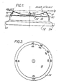
- FIG 1 shows an apparatus 10 which includes a circular housing 12 in which graduated scale cards 14, 16 are supported.
- the lower scale card 14 is of larger diameter than the upper card 16 and is maintained in a fixed orientation by a compass or compass repeater in the conventional manner by means not shown.
- the upper card 16 is fixed relative to the ship on which the apparatus is mounted.
- Both scale cards 14, 16 have gradua-- tion lines extending radially inwards from their peripheries (see Figure 2).
- An upper wall portion 18 of the housing 12 tapers inwardly towards the top of the housing 10 and its inner surface is polished to provide a frusto-conical mirror surface 22 spaced from the graduation lines on the scale cards 14, 16.
- the numerals indicating degrees on the scale cards 14, 16 are laterally inverted (see Figure 2) so that they can be read normally after reflection in the mirror surface 22.
- the housing 12 has an open circular top which is closed by a downwardly dished transparent circular panel 30, conveniently made from glass or plastics material. At its centre the dished panel 30 carries an open sight 20 in the form of an upright pin tapering to a point at its upper end.
- a lower part of the housing 12 has bearings 24 allowing the apparatus to be gimbal mounted on the ship's deck.
- Figure 2 shows the scale cards 14, 16 having graduation lines signifying angles and reversed figures indicating degrees. For clarity, only some of the graduation lines and figures are shown.
- the sight 20 is aligned by eye as shown in Figure 1 with the object and the bearing of the object is read-off from the scale cards 14, 16 reflected in the mirror surface 22 at the point diametrically opposite, the upper card 16 providing a bearing relative to the ship and the lower card 14 an absolute bearing.
- the images reflected by the surface 22 of the graduation lines of the scale cards lying to each side of the graduation line which is diametrically opposite the user's eye will be curved and only the line which is diametrically opposite will provide an image which is a rectilinear. Accordingly, the graduation line on each respective scale card 14, 16 which corresponds to the bearing of the sighted object can be identified and, indeed, the sight 20 may be dispensed with, as shown in the modified apparatus of Figure 4.
- Figure 4 shows an apparatus 40 which is identical to the apparatus 10 shown in Figure 1 except that the sight 20 is omitted.
- the elements of Figure 4 are indicated with reference numerals. identical to the corresponding elements of Figure 1.
- FIG 3 shows another modified apparatus 50 and corresponding elements are again indicated by the same numerals as in Figures 1 and 4.
- the apparatus 50 is identical to the apparatus 10 of Figure 1 with the exception that its housing 12 has a cylindrical upper wall portion 52 which is polished on its inner surface to provide a further cylindrical mirror surface 54 and that the open sight 20 of the apparatus 10 is replaced by a shorter cylindrical pin 56 also tapering to a point at its upper end.
- the apparatus 10 or 50 shown in Figure 1 or Figure 3 may be conveniently fitted with a conventional attachment for taking bearings of celestial objects or objects exposed to glare.
- the attachment has a socket which is fitted over the pin 20 or 56 for rotational movement relative to the housing 12 of the apparatus 10 or 50.
- the attachment includes a glass panel, which may be a magnifying lens, having a sighting line for alignment with the sighted object and preferably includes a coloured reflector plate which is movable into a position in which it protects the user's eyes from glare.
- the attachment may also include means, for example a spirit level, for adjusting the apparatus on its gimbals into a horizontal position.
- the user of the apparatus described does not need to place himself and his eye close to the apparatus. A reasonably accurate bearing can be obtained by a user standing as far as 0.5 m away from the apparatus. Moreover, the apparatus is particularly simple to use and instruction of the user prior to use of the apparatus need be only brief.
Landscapes
- Physics & Mathematics (AREA)
- Engineering & Computer Science (AREA)
- General Physics & Mathematics (AREA)
- Radar, Positioning & Navigation (AREA)
- Remote Sensing (AREA)
- Telescopes (AREA)
- Lenses (AREA)
Claims (9)
Applications Claiming Priority (2)
| Application Number | Priority Date | Filing Date | Title |
|---|---|---|---|
| GB8222235 | 1982-08-02 | ||
| GB8222235 | 1982-08-02 |
Publications (3)
| Publication Number | Publication Date |
|---|---|
| EP0100683A2 EP0100683A2 (de) | 1984-02-15 |
| EP0100683A3 EP0100683A3 (en) | 1984-03-21 |
| EP0100683B1 true EP0100683B1 (de) | 1986-10-22 |
Family
ID=10532057
Family Applications (1)
| Application Number | Title | Priority Date | Filing Date |
|---|---|---|---|
| EP19830304464 Expired EP0100683B1 (de) | 1982-08-02 | 1983-08-02 | Peilungsvorrichtung |
Country Status (2)
| Country | Link |
|---|---|
| EP (1) | EP0100683B1 (de) |
| DE (1) | DE3367118D1 (de) |
Families Citing this family (1)
| Publication number | Priority date | Publication date | Assignee | Title |
|---|---|---|---|---|
| FI84756C (fi) * | 1990-06-11 | 1992-01-10 | Sisteco Ltd Oy | Kompass. |
Family Cites Families (2)
| Publication number | Priority date | Publication date | Assignee | Title |
|---|---|---|---|---|
| GB384847A (en) * | 1932-02-19 | 1932-12-15 | George Paxton | Improvements in or relating to apparatus for facilitating the reading of navigational instruments |
| GB445310A (en) * | 1934-11-15 | 1936-04-07 | Burton Mortimer Green | Improvements in or relating to azimuth circles |
-
1983
- 1983-08-02 DE DE8383304464T patent/DE3367118D1/de not_active Expired
- 1983-08-02 EP EP19830304464 patent/EP0100683B1/de not_active Expired
Also Published As
| Publication number | Publication date |
|---|---|
| EP0100683A3 (en) | 1984-03-21 |
| EP0100683A2 (de) | 1984-02-15 |
| DE3367118D1 (en) | 1986-11-27 |
Similar Documents
| Publication | Publication Date | Title |
|---|---|---|
| US4912853A (en) | Reticle plate and method for establishment of a north-oriented or south-oriented line by circumpolar orientation | |
| US6647633B2 (en) | Low profile compass with removable protective cover and magnetic bull's eye alignment system | |
| AU647771B2 (en) | Electro optical apparatus | |
| US3752591A (en) | Sextant with digital readout and night viewing capability | |
| US4402140A (en) | Telescope with compass | |
| EP0100683B1 (de) | Peilungsvorrichtung | |
| US4294541A (en) | Bi-periscopic instrument for use in determining terrestrial positions through celestial observation | |
| US1966850A (en) | Drift angle indicator | |
| US2189790A (en) | Sextant | |
| US5056232A (en) | Remote light source responsive visual time indicator | |
| US2839833A (en) | Stabilized celestial navigation instrument | |
| US811777A (en) | Angle-measuring instrument. | |
| US4763419A (en) | Optical viewing system | |
| US2995972A (en) | Polaris circle grid | |
| US2173142A (en) | Optical system for sextants and the like | |
| US2471686A (en) | Celestial navigation instrument | |
| US3853089A (en) | Course selector and indicator | |
| GB1603599A (en) | Telescope with compass | |
| EP0086618B1 (de) | Kompass | |
| US3353440A (en) | Navigation pelorus | |
| US4462684A (en) | Single wheel celestial navigator | |
| EP0025695B1 (de) | Instrument zum Messen oder Markieren des Abstandes eines Punktes von einer Bezugsfläche oder Linie | |
| US2028063A (en) | Azimuth compass | |
| US1875829A (en) | Surveying instrument | |
| US2389143A (en) | Sextant |
Legal Events
| Date | Code | Title | Description |
|---|---|---|---|
| PUAI | Public reference made under article 153(3) epc to a published international application that has entered the european phase |
Free format text: ORIGINAL CODE: 0009012 |
|
| PUAL | Search report despatched |
Free format text: ORIGINAL CODE: 0009013 |
|
| AK | Designated contracting states |
Designated state(s): DE FR GB IT NL |
|
| AK | Designated contracting states |
Designated state(s): DE FR GB IT NL |
|
| 17P | Request for examination filed |
Effective date: 19840529 |
|
| GRAA | (expected) grant |
Free format text: ORIGINAL CODE: 0009210 |
|
| ITF | It: translation for a ep patent filed | ||
| AK | Designated contracting states |
Kind code of ref document: B1 Designated state(s): DE FR GB IT NL |
|
| REF | Corresponds to: |
Ref document number: 3367118 Country of ref document: DE Date of ref document: 19861127 |
|
| ET | Fr: translation filed | ||
| RAP2 | Party data changed (patent owner data changed or rights of a patent transferred) |
Owner name: VOUSDEN, JAMES BERNARD Owner name: S.G. BROWN LIMITED |
|
| RAP2 | Party data changed (patent owner data changed or rights of a patent transferred) |
Owner name: VOUSDEN, JAMES BERNARD C/O S G BROWN LIMITED Owner name: S.G. BROWN LIMITED |
|
| PLBE | No opposition filed within time limit |
Free format text: ORIGINAL CODE: 0009261 |
|
| STAA | Information on the status of an ep patent application or granted ep patent |
Free format text: STATUS: NO OPPOSITION FILED WITHIN TIME LIMIT |
|
| PGFP | Annual fee paid to national office [announced via postgrant information from national office to epo] |
Ref country code: NL Payment date: 19870831 Year of fee payment: 5 |
|
| 26N | No opposition filed | ||
| PG25 | Lapsed in a contracting state [announced via postgrant information from national office to epo] |
Ref country code: GB Effective date: 19890802 |
|
| PG25 | Lapsed in a contracting state [announced via postgrant information from national office to epo] |
Ref country code: NL Effective date: 19900301 |
|
| GBPC | Gb: european patent ceased through non-payment of renewal fee | ||
| NLV4 | Nl: lapsed or anulled due to non-payment of the annual fee | ||
| PG25 | Lapsed in a contracting state [announced via postgrant information from national office to epo] |
Ref country code: FR Effective date: 19900427 |
|
| PG25 | Lapsed in a contracting state [announced via postgrant information from national office to epo] |
Ref country code: DE Effective date: 19900501 |
|
| REG | Reference to a national code |
Ref country code: FR Ref legal event code: ST |