EP0100650B1 - Vorrichtung und Verfahren zur Erzeugung von akustischen Anzeigen - Google Patents
Vorrichtung und Verfahren zur Erzeugung von akustischen Anzeigen Download PDFInfo
- Publication number
- EP0100650B1 EP0100650B1 EP83304350A EP83304350A EP0100650B1 EP 0100650 B1 EP0100650 B1 EP 0100650B1 EP 83304350 A EP83304350 A EP 83304350A EP 83304350 A EP83304350 A EP 83304350A EP 0100650 B1 EP0100650 B1 EP 0100650B1
- Authority
- EP
- European Patent Office
- Prior art keywords
- sounds
- sound
- components
- range
- frequency
- Prior art date
- Legal status (The legal status is an assumption and is not a legal conclusion. Google has not performed a legal analysis and makes no representation as to the accuracy of the status listed.)
- Expired
Links
- 238000000034 method Methods 0.000 title claims description 17
- 230000002123 temporal effect Effects 0.000 claims description 5
- KJLLKLRVCJAFRY-UHFFFAOYSA-N mebutizide Chemical compound ClC1=C(S(N)(=O)=O)C=C2S(=O)(=O)NC(C(C)C(C)CC)NC2=C1 KJLLKLRVCJAFRY-UHFFFAOYSA-N 0.000 claims description 3
- 230000001419 dependent effect Effects 0.000 claims 3
- 230000003247 decreasing effect Effects 0.000 claims 1
- 238000001228 spectrum Methods 0.000 description 13
- 230000006870 function Effects 0.000 description 7
- 238000012360 testing method Methods 0.000 description 6
- 230000014509 gene expression Effects 0.000 description 5
- 230000000873 masking effect Effects 0.000 description 5
- 241000826860 Trapezium Species 0.000 description 4
- 238000004458 analytical method Methods 0.000 description 3
- 238000010586 diagram Methods 0.000 description 3
- 230000000694 effects Effects 0.000 description 3
- 230000010354 integration Effects 0.000 description 2
- 230000007774 longterm Effects 0.000 description 2
- 230000008569 process Effects 0.000 description 2
- 206010063602 Exposure to noise Diseases 0.000 description 1
- 230000003321 amplification Effects 0.000 description 1
- 230000008901 benefit Effects 0.000 description 1
- 210000004556 brain Anatomy 0.000 description 1
- 230000008859 change Effects 0.000 description 1
- 238000006243 chemical reaction Methods 0.000 description 1
- 238000004891 communication Methods 0.000 description 1
- 230000006835 compression Effects 0.000 description 1
- 238000007906 compression Methods 0.000 description 1
- 238000012937 correction Methods 0.000 description 1
- 230000007423 decrease Effects 0.000 description 1
- 230000007257 malfunction Effects 0.000 description 1
- 238000004519 manufacturing process Methods 0.000 description 1
- 238000003199 nucleic acid amplification method Methods 0.000 description 1
- 230000004044 response Effects 0.000 description 1
- 230000033764 rhythmic process Effects 0.000 description 1
- 238000005070 sampling Methods 0.000 description 1
- 238000012549 training Methods 0.000 description 1
- 230000000007 visual effect Effects 0.000 description 1
Images


Classifications
-
- B—PERFORMING OPERATIONS; TRANSPORTING
- B06—GENERATING OR TRANSMITTING MECHANICAL VIBRATIONS IN GENERAL
- B06B—METHODS OR APPARATUS FOR GENERATING OR TRANSMITTING MECHANICAL VIBRATIONS OF INFRASONIC, SONIC, OR ULTRASONIC FREQUENCY, e.g. FOR PERFORMING MECHANICAL WORK IN GENERAL
- B06B1/00—Methods or apparatus for generating mechanical vibrations of infrasonic, sonic, or ultrasonic frequency
- B06B1/02—Methods or apparatus for generating mechanical vibrations of infrasonic, sonic, or ultrasonic frequency making use of electrical energy
- B06B1/0207—Driving circuits
- B06B1/0223—Driving circuits for generating signals continuous in time
- B06B1/0269—Driving circuits for generating signals continuous in time for generating multiple frequencies
- B06B1/0276—Driving circuits for generating signals continuous in time for generating multiple frequencies with simultaneous generation, e.g. with modulation, harmonics
-
- G—PHYSICS
- G08—SIGNALLING
- G08B—SIGNALLING OR CALLING SYSTEMS; ORDER TELEGRAPHS; ALARM SYSTEMS
- G08B3/00—Audible signalling systems; Audible personal calling systems
- G08B3/10—Audible signalling systems; Audible personal calling systems using electric transmission; using electromagnetic transmission
Definitions
- the present invention relates to the generation of auditory indicators such as alarms or attensons, that is sounds for gaining attention.
- auditory warnings are used for example on the flight decks of aircraft, in the operations rooms of ships, in the driving cabs of trains, in electrical generating stations, in factories, in operating theatres, and many other places.
- apparatus for providing at least four auditory indicators comprising
- the auditory indicators that is the sounds generated in the two aspects of the invention are usually alarms or attensons (that is attention getting sounds).
- the number of sounds which can be generated depends on the purpose for which they are required. In many applications at least four such sounds are needed. Hence the conditions are usually either equipment malfunctions or the need to gain someone's attention.
- One advantage of the present invention is that the sounds generated are clearly audible over background noise but not too loud to be disruptive. Using four frequency components is an aid in ensuring that distinctive sounds can be provided for many warnings and with these components in the specified level range sounds do not substantially change character with expected changes in background noise.
- threshold in this specification means that level of a component which would be just audible over the expected maximum background noise.
- General and simplified expressions for threshold are given later.
- components are quasi-harmonically related if the frequency of each component is in a range plus or minus ten per cent of a respective integral number of times a common fundamental frequency between 150 and 1000 Hz.
- each component may have a frequency which is an integral number of times the fundamental frequency or one or more components may have frequencies within ten per cent of an integral number times the fundamemtal frequency. Since one of the integral numbers may be one, one of the components may be at the fundamental frequency but, as is explained below, the components of a sound generated by an apparatus or method of the invention need not include the fundamental. It will be apparent from the frequency range specified that each component may be harmonically related to the fundamental. The use of quasi-harmonically related components increases the urgency of a sound.
- each sound is made up of bursts of short . pulses so that they have distinctive temporal patterns, the levels of the pulses within each burst varying in a predetermined way and with varying predetermined intervals between pulses.
- the said maximum power level of components is then the level which occurs in a maximum amplitude pulse.
- the components of the sounds preferably have frequencies in the range 0.5 kHz to 4 kHz and the residue pitch (i.e. the fundamental frequency) of each sound is between 150 and 1000 Hz.
- each sound has at least six quasi-harmonically related components.
- the threshold for the environment concerned In order to set the appropriate levels of components for an auditory warning, the threshold for the environment concerned must be determined.
- the auditory system of the ear and brain processes incoming sound with a fairly detailed frequency analysis, and it is in essence this analysis which determines whether one sound masks another.
- the auditory system is largely insensitive to the phase of individual frequency components, particularly when the masker is a noise, and auditory warnings are long compared with respect to the integration time of the ear.
- a simple power spectrum model can provide quite an accurate representation of a frequency analysis.
- the filter shape can be measured experimentally (see Patterson, R.D. "Auditory Filter Shapes Derived With Noise Stimuli", Journal of Acoustical Society of America, Volume 59, No. 3, March 1976, pages 640 to 654) and is typical of a resonant, physical system: it has a well defined pass band with an equivalent rectangular bandwidth, BW ER , that is roughly 15% of the centre frequency.
- BW ER equivalent rectangular bandwidth
- the parameter p determines the width of the pass band of the filter and the function is a pair of back to back exponentials (e- P9 ) with the peak rounded off by the term (1+pg) and the dynamic range of the exponential limited by a floor, r.
- the term (1-r) simply ensures that there is neither loss nor gain at the centre frequency.
- the filter shape is substituted into the general masking equation to provide an expression for calculating threshold from an arbitrary noise ' spectrum.
- the proportionality constant, K can be assumed to have a value of unity for practical purposes (particularly on flight decks).
- the general expression for the threshold is
- the constant f e is required to convert the normalized frequency domain to physical power. Since the limit on the dynamic range is implemented by means of a constant, r, the integration is restricted in frequency to 0.8. This expression can be used to predict threshold whenever the total noise power does not exceed about 95 dBA. Above 95 dBA the auditory filter broadens and a correction must be included.
- the noise spectra are fairly smooth.
- the noise spectrum can be approximated by a constant NL c : the auditory filter can be approximated by its equivalent bandwidth, BW ER ; and the masking equation reduces to a simple form:- where BW ER is in Hz and NL e is in (dynes/cm 2 )/Hz.
- BW ER is in Hz
- NL e is in (dynes/cm 2 )/Hz.
- both the noise level and the signal power at threshold are expressed in dB SPL; that is in tenths of log-units, where the reference level is 0.0002 dynes/cm 2 .
- a more convenient form of the above simple form is where 10 log P s and 10 log NL e are in dB SPL.
- BW ER is approximately 0.15-f c and it is the width that a rectangular filter with unit height must have to yield the same total area as the auditory filter. Provided the noise spectrum does not fall more than 6 dB across the equivalent rectangular filter, the average noise level in dB SPL can be approximated by the value at f e .
- the procedure for calculating threshold as a function of frequency is illustrated in Figure 1.
- the spectrum of the flight deck noise is designated 10 and two auditory filters with characteristics 11 and 12 are shown centred at 1 and 4 kHz respectively. Their rectangular equivalents 13 and 14, respectively, are also shown.
- the appropriate noise level for calculating the threshold at 1 kHz is 50 dB SPL and has the same value at 4 kHz.
- threshold at 1 and 4 kHz is These vqlues are plotted at points 15 and 16 and similar points are plotted to give the complete threshold curve as illustrated by the line 17.
- a better threshold value is, of course, obtained by carrying out the convulution of the general expression for threshold given above, where N(g) is the measured noise level for the environment concerned.
- a lower frequency limit of 500 Hz for components of warning sounds is preferable.
- An upper limit of 4 kHz is chosen because about this frequency hearing ability deteriorates with age and may be damaged by long term exposure to noise.
- the frequency response of existing intercom systems and headsets falls off rapidly above 4 kHz.
- at least four harmonically related frequencies in the range 500 to 4000 Hz are chosen for each warning, for example the frequencies might be 600, 1200, 1800, 2400, 3000 Hz.
- the apparent pitch of the sound (the residue pitch) is equal to the interval, that is an apparent fundamental occurs at a frequency equal to the interval.
- components having frequencies of 900, 1050, 1200 and 1350 Hz have an apparent pitch of 150 Hz and are harmonically related.
- the frequencies chosen for the components may omit the fundamental as long as they are harmonically related.
- Preferably six or more components are chosen for each sound since this reduces the effect of masking one or two components and helps maintain the character of the sound under varying conditions. More scope is also given for making the sounds distinctive.
- the threshold curve for the flight deck is now determined in the way described above and a level in the range 15 to 30 dB but preferably 25 dB above threshold is chosen for each component, with at least halfthe components more than 20 dB above threshold.
- the frequency of one or more components is now changed to make it slightly inharmonic (but still within the term quasi-harmonic as specified above), and to make a sound more urgent the number of inharmonic components is increased.
- Figure 2 which relates to the BAC 1-11 aircraft as far as flight deck noise is concerned.
- Lines 20 and 21 show the spectra of flight deck noise during steady climb and steep descent, respectively, and line 22 shows the spectrum of level flight.
- the threshold is shown by a line 23 as calculated from the level flight spectrum 22 which is greater than spectra 20 and 21 and therefore represents the expected range of background noise.
- Lines 24 and 25 show lower and upper limits for warning sound components and are positioned approximately 15 and 25 dB, respectively, above threshold.
- Five sound components 26 to 30 chosen according to the invention are also illustrated.
- the chosen component frequencies and levels are now entered into a computer and an inverse Fourier transform is carried out.
- the transform length may, for example, be 1024 points each with a resolution of 12 bits.
- the result is 1024 samples representing a single pulse of approximately 100 msec duration of a warning sound when read out at 10,000 samples per second. These samples are stored, in the computer memory.
- a "cosine gate” is applied to the first and last 100 samples of the stored pulse; that is to say these samples are multiplied .by corresponding samples of an inverted cosine function so offset that the smallest sample is zero (not negative as in a normal inverted cosine function). For the first 100 samples the cosine function increases from zero and for the last 100 samples the cosine function decreases to zero.
- samples of the modified pulse are held in computer storage and these samples are later transferred to a programmable read-only memory (PROM) in warning equipment to form the basis of warning sounds. Samples for other warning sounds derived in the same way are also stored in the PROM.
- PROM programmable read-only memory
- the sounds can be regarded as being in pulse code modulation (PCM) form but if required the samples may be recorded to store each sound in . Delta modulated form, for example.
- PCM pulse code modulation
- the pulses in the warning apparatus of the embodiment are assembled into bursts and a number of bursts of different types form a complete warning.
- a burst having six identical 0.1 second pulses and a basic temporal pattern is shown in Figure 3a while the same burst modified with a loudness contour is shown in Figure 3b.
- the pulse spacing is compressed in Figure 3c and compression is taken to the limit in Figure 3d.
- the types of burst shown in Figures 3a to 3d are designated types 1 to 4 in this specification. Using short pulses and starting with a low-level pulse makes the warnings less anoying, less disrruptive and less startling.
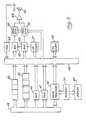
- FIG. 4 has a single horizontal time axis joined as indicated by arrows.
- Each trapezium shown contains a number showing the type of burst employed and the heights of the trapeziums indicate the amplitudes (or maximum amplitudes) of the pulses in the bursts. Also included are rectangles indicating voice warnings and again the heights of the rectangles indicate amplitude.
- a PROM 32 is regarded as divided into four sections corresponding to four respective warnings and each section comprises a relatively large portion containing the 1024 samples of one pulse of one warning and a relatively small portion containing variables specifying the pulses of different types of burst. These variables are: T-the time between the pulse and the next pulse, R-the rate at which the samples are read out (that is the pitch of the pulse) and A-the amplitude of the pulse. R can be varied from pulse to pulse by a small amount to make warnings more distinctive, for example with a nominal sampling rate of 10 kHz variations from 9 to 11 kHz may be employed.
- a ROM 33 also regarded as being in four sections contains samples of voice warnings corresponding to the four warnings of the PROM 32, such samples allowing the voice warnings to be generated after digital-to-analogue conversion and amplification. No details of voice warnings are given since they are not part of the present invention.
- a signal is passed to a microprocessor 35.
- the sensors and known ways of registering their output signals which are already used in aircraft may be employed to provide the required input to the microprocessor.
- a program is then started causing a series of the variables T, R and A to be passed by way of a data bus 40 to a mark/space clock 36, a sample rate clock 37 and programmable attenuators 38 and 39.
- a flow chart for this program is shown in Figure 6 and described below.
- the pulse samples from the appropriate portion of the PROM 32 are passed to digital-to-analogue converters (DACs) 42 and 43, two converters being provided as a safety measure to give redundancy.
- DACs digital-to-analogue converters
- the samples are applied to the converters at a sample rate determined by the sample rate clock 37 which is under the control of the variable R.
- the output signals from the DACs 42 and 43 are passed t6 the programmable attenuators 38 and 39 which have been set according to the variable A. From these attenuators signals pass by way of a power amplifier 44 to a loudspeaker 45.
- a ROM 46 contains the above mentioned program and a RAM 47 provides a working space for the microprocessor 35.
- the RAM 47 and the ROMs 32, 33 and 46 are addressed by way of an address bus 48.
- a preflight check is automatically carried out by the system on switch-on and comprises playing each warning in turn and checking the level by means of a microphone 51 and an analogue-to-digital converter 52 which passes levels back to the microprocessor 35 where they are checked against the expected levels.
- FIG. 6 A flow chart for the above mentioned program is shown in Figure 6 in a form which can be translated into many suitable languages for assembly into machine code and storage in the ROM 46. Since this process is one well known to computer programmers it is not described here.
- the ROM 46 also contains other programs of known types for starting and housekeeping purposes, and for the automatic test mentioned, but these programs are not described because they are either conventional or not directly concerned with the invention.
- control words for this warning are fetched into the working space RAM 47 in an operation 56.
- One set of control words corresponding to each of the trapeziums in the warning and each rectangle, and one control word identifying the waveform samples and the voice warning to be used are stored.
- Each set of words has sub-groups of three words specifying T, R and A for each pulse in that burst.
- the set of control words for the trapezium 3 comprises six sub-groups each specifying T, R and A for one of the pulses shown in Figure 3c.
- the variables for the first burst are first fetched from PROM 32 in an operation 57 and held in the RAM 47. These three variables are then loaded by the processor 35 in an operation 58 into the mark space clock 36, the sample rate clock 37 and the programmable attenuators 38 and 39. Next the 1024 amplitude samples for that warning as identified by the operation 55 are passed to the DACs 42 and 43 at a rate set by the sample rate clock 37 and determined by R. Having read out all these samples an operation 60 is carried out in which the clock 36 is counted down from T to zero, thus giving the spacing between the current pulse and the next pulse.
- a test 61 is then carried out to determine whether the burst is complete and if not a loop 62 back to the operation 58 follows to allow the next pulse to be generated. When the last pulse has been generated the test 63 follows to determine whether another warning of higher or equal priority has occurred. If not then a test 64 determines whether the last burst in the warning has occurred so that by following a loop 65 in the remainder of the bursts in the warning are eventually provided. When a voice warning occurs it is considered as a single burst comprising one long "pulse" with variables T, R and A and the samples read out in the operation 59 are those of the appropriate voice waveform.
- Each warning contains at least one pulse in which all four quasi-harmonically related components are in the range 15 to 30 dB above threshold and at least half the components are more than 20 dB above threshold. Preferably, however, more than half the pulses in each warning contain four quasi-harmonically related components in the range 15 to 30 dB above threshold.
- the gain of the amplifier 44 is such that with the programmable attenuators set for an attenuation of zero the required sound output level is obtained from the loudspeaker 45.
- the attenuators 38 and 39 are set to zero.
- the loudest pulse is tested and the A values in the PROM 32 are all changed by the addition or subtraction of the same number until the correct level is obtained.
- the desired waveform is loaded into the PROM 32 in the usual way but as part of the setting up procedure these levels are modified as mentioned above.
- a potentionmeter controlling the gain of the amplifier 44 is set by the manufacturer to give the required level in the loudest pulse.
- auditory warning apparatus may, perhaps to give prominence to certain alarms, generate a few additional sounds having at least one component outside the range 15 to 30 dB above threshold.
- auditory indicators are used in other environments such as power stations, ships or trains the same general principles are observed but the invention may be put into effect in rather different ways so long as at least four sounds are provided and each sound contains at least four quasi-harmonically related components in the range 15 to 30 dB above threshold.
Landscapes
- Physics & Mathematics (AREA)
- Electromagnetism (AREA)
- General Physics & Mathematics (AREA)
- Engineering & Computer Science (AREA)
- Mechanical Engineering (AREA)
- Measurement Of Mechanical Vibrations Or Ultrasonic Waves (AREA)
Claims (15)
Applications Claiming Priority (2)
| Application Number | Priority Date | Filing Date | Title |
|---|---|---|---|
| GB8222029 | 1982-07-30 | ||
| GB8222029 | 1982-07-30 |
Publications (2)
| Publication Number | Publication Date |
|---|---|
| EP0100650A1 EP0100650A1 (de) | 1984-02-15 |
| EP0100650B1 true EP0100650B1 (de) | 1986-03-26 |
Family
ID=10532015
Family Applications (1)
| Application Number | Title | Priority Date | Filing Date |
|---|---|---|---|
| EP83304350A Expired EP0100650B1 (de) | 1982-07-30 | 1983-07-27 | Vorrichtung und Verfahren zur Erzeugung von akustischen Anzeigen |
Country Status (4)
| Country | Link |
|---|---|
| US (2) | US4644327A (de) |
| EP (1) | EP0100650B1 (de) |
| DE (1) | DE3362689D1 (de) |
| GB (1) | GB2124417B (de) |
Families Citing this family (35)
| Publication number | Priority date | Publication date | Assignee | Title |
|---|---|---|---|---|
| US4644327A (en) * | 1982-07-30 | 1987-02-17 | National Research Development Corp. | Methods for generating auditory indicators |
| GB2178535B (en) * | 1985-07-27 | 1988-11-09 | Rolls Royce | Digital noise generator |
| DE3812144A1 (de) * | 1988-04-12 | 1989-10-26 | Siemens Ag | Schaltungsanordnung zur ausgabe von akustischen alarmierungsmeldungen fuer gefahrenmeldeanlagen |
| DE3823824C1 (de) * | 1988-07-14 | 1989-10-19 | Blaupunkt-Werke Gmbh, 3200 Hildesheim, De | |
| US5012221A (en) * | 1989-03-24 | 1991-04-30 | Siren Sounds, Inc. | Emergency vehicle audible warning system and method |
| JPH04119062A (ja) * | 1990-09-10 | 1992-04-20 | Fuji Xerox Co Ltd | 異常処理教示装置 |
| US5378807A (en) * | 1991-08-08 | 1995-01-03 | University Of Massachusetts At Lowell | γ-poly(glutamic acid) esters |
| US5262757A (en) * | 1992-02-07 | 1993-11-16 | Cyclert, Inc. | Electronic signaling device for bicycles and the like |
| AUPM282493A0 (en) * | 1993-12-06 | 1994-01-06 | Robert Bosch (Australia) Proprietary Ltd. | A siren unit |
| US5633625A (en) * | 1995-03-20 | 1997-05-27 | Saturn Electronics & Engineering, Inc. | Electronic chime module and method |
| ES2182984T3 (es) * | 1995-07-07 | 2003-03-16 | Sound Alert Ltd | Mejoras relativas a dispositivos de localizacion. |
| US6582378B1 (en) * | 1999-09-29 | 2003-06-24 | Rion Co., Ltd. | Method of measuring frequency selectivity, and method and apparatus for estimating auditory filter shape by a frequency selectivity measurement method |
| US7346172B1 (en) | 2001-03-28 | 2008-03-18 | The United States Of America As Represented By The United States National Aeronautics And Space Administration | Auditory alert systems with enhanced detectability |
| US7048692B2 (en) * | 2002-01-22 | 2006-05-23 | Rion Co., Ltd. | Method and apparatus for estimating auditory filter shape |
| EP1414022A4 (de) * | 2002-04-01 | 2005-06-08 | Matsushita Electric Industrial Co Ltd | Ansagevorrichtung |
| US7079036B2 (en) * | 2003-08-20 | 2006-07-18 | Bed-Check Corporation | Method and apparatus for alarm volume control using pulse width modulation |
| US7382233B2 (en) * | 2004-05-08 | 2008-06-03 | Scott Steinetz | Sampling playback doorbell system |
| US7079014B2 (en) * | 2004-05-08 | 2006-07-18 | Scott Steinetz | Digital sampling playback doorbell system |
| US7268671B2 (en) * | 2004-06-22 | 2007-09-11 | Caterpillar Inc. | Shaped modulation audible alarm |
| US7295121B2 (en) * | 2004-08-27 | 2007-11-13 | Sarnoff Corporation | Methods and apparatus for aurally presenting notification message in an auditory canal |
| US8302151B2 (en) * | 2008-06-02 | 2012-10-30 | International Business Machines Corporation | Improving comprehension of information in a security enhanced environment by representing the information in audio form |
| US8760271B2 (en) | 2011-11-10 | 2014-06-24 | Honeywell International Inc. | Methods and systems to support auditory signal detection |
| US9031776B2 (en) | 2012-11-29 | 2015-05-12 | Nissan North America, Inc. | Vehicle intersection monitoring system and method |
| US9620014B2 (en) | 2012-11-29 | 2017-04-11 | Nissan North America, Inc. | Vehicle intersection monitoring system and method |
| US9349291B2 (en) | 2012-11-29 | 2016-05-24 | Nissan North America, Inc. | Vehicle intersection monitoring system and method |
| US9020728B2 (en) | 2013-01-17 | 2015-04-28 | Nissan North America, Inc. | Vehicle turn monitoring system and method |
| US8990001B2 (en) | 2013-07-26 | 2015-03-24 | Nissan North America, Inc. | Vehicle collision monitoring method |
| US9177478B2 (en) | 2013-11-01 | 2015-11-03 | Nissan North America, Inc. | Vehicle contact avoidance system |
| US9485247B2 (en) | 2014-03-04 | 2016-11-01 | Nissan North America, Inc. | On-board vehicle communication system and method |
| US9324233B2 (en) | 2014-03-04 | 2016-04-26 | Nissan North America, Inc. | Vehicle contact warning method and system |
| US9031758B1 (en) | 2014-03-04 | 2015-05-12 | Nissan North America, Inc. | On-board vehicle control system and method for determining whether a vehicle is within a geographical area of interest |
| US9153132B2 (en) | 2014-03-04 | 2015-10-06 | Nissan North America, Inc. | On-board vehicle control system and method for determining whether a value is within an area of interest for extraneous warning suppression |
| US9694737B2 (en) | 2014-06-16 | 2017-07-04 | Nissan North America, Inc. | Vehicle headlight control system and method |
| US9776614B2 (en) | 2014-10-03 | 2017-10-03 | Nissan North America, Inc. | Method and system of monitoring passenger buses |
| US9778349B2 (en) | 2014-10-03 | 2017-10-03 | Nissan North America, Inc. | Method and system of monitoring emergency vehicles |
Family Cites Families (12)
| Publication number | Priority date | Publication date | Assignee | Title |
|---|---|---|---|---|
| US3173136A (en) * | 1960-12-01 | 1965-03-09 | Duane E Atkinson | Variable volume horn system |
| US3504364A (en) * | 1966-11-07 | 1970-03-31 | William E Abel | Electronic siren |
| US3872470A (en) * | 1973-04-18 | 1975-03-18 | Airco Inc | Audible signal generating apparatus having selectively controlled audible output |
| US4086589A (en) * | 1976-03-08 | 1978-04-25 | Industrial Electronics Service Co. | Audible electronic warning system |
| JPS52123223A (en) * | 1976-04-08 | 1977-10-17 | Toshiba Corp | Electronic circuit for music box |
| US4088995A (en) * | 1977-02-25 | 1978-05-09 | International Telephone And Telegraph Corporation | System for selectively operable dual simultaneous siren broadcast from a single speaker |
| FR2413730A1 (fr) * | 1977-12-28 | 1979-07-27 | Accumulateurs Fixes | Dispositif de commande d'un avertisseur electronique |
| GB2058497B (en) * | 1979-08-31 | 1984-02-29 | Nissan Motor | Voice warning system with volume control |
| US4280123A (en) * | 1980-05-05 | 1981-07-21 | General Signal Corporation | Multitone signaling device |
| GB2084783B (en) * | 1980-10-02 | 1985-06-19 | Production Eng Res | Audio system |
| US4417218A (en) * | 1981-06-19 | 1983-11-22 | The United States Of America As Represented By The Secretary Of The Navy | Linearizing circuit for a high frequency voltage controlled oscillator |
| US4644327A (en) * | 1982-07-30 | 1987-02-17 | National Research Development Corp. | Methods for generating auditory indicators |
-
1983
- 1983-07-20 US US06/515,501 patent/US4644327A/en not_active Expired - Lifetime
- 1983-07-27 DE DE8383304350T patent/DE3362689D1/de not_active Expired
- 1983-07-27 GB GB08320204A patent/GB2124417B/en not_active Expired
- 1983-07-27 EP EP83304350A patent/EP0100650B1/de not_active Expired
-
1986
- 1986-10-10 US US06/917,685 patent/US4768022A/en not_active Expired - Lifetime
Also Published As
| Publication number | Publication date |
|---|---|
| EP0100650A1 (de) | 1984-02-15 |
| US4768022A (en) | 1988-08-30 |
| DE3362689D1 (en) | 1986-04-30 |
| GB8320204D0 (en) | 1983-09-01 |
| GB2124417B (en) | 1985-09-18 |
| GB2124417A (en) | 1984-02-15 |
| US4644327A (en) | 1987-02-17 |
Similar Documents
| Publication | Publication Date | Title |
|---|---|---|
| EP0100650B1 (de) | Vorrichtung und Verfahren zur Erzeugung von akustischen Anzeigen | |
| Zwicker | Temporal effects in simultaneous masking by white‐noise bursts | |
| US4935952A (en) | Alarm-responsive apparatus and method | |
| JP2529129B2 (ja) | 信号圧縮装置及び方法 | |
| Whittle et al. | The audibility of low-frequency sounds | |
| US4163216A (en) | System for transmitting airport weather information | |
| EP1607939B1 (de) | Sprachsignalkomprimierungseinrichtung, sprachsignalkomprimierungsverfahren und programm | |
| GB2171518A (en) | Glass break detector | |
| Terhune et al. | The harp seal, Pagophilus groenlandicus (Erxleben, 1777). X. The air audiogram | |
| HK33296A (en) | Voice switching apparatus and method | |
| AU2021273630A1 (en) | Characterization of reverberation of audible spaces | |
| Schroeder | New results concerning monaural phase sensitivity | |
| EP0298046A2 (de) | Gerät zum Messen, Anzeigen und Überwachen des Schalldruckes oder -niveaus in einer Umgebung | |
| JPS6257040B2 (de) | ||
| US5883573A (en) | Message generation supervision system | |
| Egan | Independence of the masking audiogram from the perstimulatory fatigue of an auditory stimulus | |
| Koshikawa et al. | The information rate of the pitch signal in speech | |
| JPS6367789B2 (de) | ||
| JPH0370240B2 (de) | ||
| Egan et al. | Detection of signals presented at random times | |
| RU2148391C1 (ru) | Устройство для измерения помехоустойчивости восприятия речи человеком | |
| Bell et al. | Closed-set effects in consonant confusion patterns | |
| JP2757968B2 (ja) | 無線操作者不在検出装置 | |
| Steed et al. | Studies on quiet threshold shift in the absence of noise | |
| JPH0675596A (ja) | スピーチおよび音響学的現象分析装置 |
Legal Events
| Date | Code | Title | Description |
|---|---|---|---|
| PUAI | Public reference made under article 153(3) epc to a published international application that has entered the european phase |
Free format text: ORIGINAL CODE: 0009012 |
|
| AK | Designated contracting states |
Designated state(s): DE FR GB IT NL SE |
|
| RAP1 | Party data changed (applicant data changed or rights of an application transferred) |
Owner name: NATIONAL RESEARCH DEVELOPMENT CORPORATION |
|
| 17P | Request for examination filed |
Effective date: 19840726 |
|
| GRAA | (expected) grant |
Free format text: ORIGINAL CODE: 0009210 |
|
| AK | Designated contracting states |
Kind code of ref document: B1 Designated state(s): DE FR GB IT NL SE |
|
| ITF | It: translation for a ep patent filed | ||
| REF | Corresponds to: |
Ref document number: 3362689 Country of ref document: DE Date of ref document: 19860430 |
|
| ET | Fr: translation filed | ||
| PLBE | No opposition filed within time limit |
Free format text: ORIGINAL CODE: 0009261 |
|
| STAA | Information on the status of an ep patent application or granted ep patent |
Free format text: STATUS: NO OPPOSITION FILED WITHIN TIME LIMIT |
|
| 26N | No opposition filed | ||
| REG | Reference to a national code |
Ref country code: GB Ref legal event code: 732 |
|
| ITPR | It: changes in ownership of a european patent |
Owner name: CESSIONE;BRITISH TECHNOLOGY GROUP LIMITED |
|
| REG | Reference to a national code |
Ref country code: FR Ref legal event code: TP |
|
| NLS | Nl: assignments of ep-patents |
Owner name: BRITISH TECHNOLOGY GROUP LTD TE LONDEN, GROOT-BRIT |
|
| ITTA | It: last paid annual fee | ||
| EAL | Se: european patent in force in sweden |
Ref document number: 83304350.8 |
|
| REG | Reference to a national code |
Ref country code: GB Ref legal event code: IF02 |
|
| PGFP | Annual fee paid to national office [announced via postgrant information from national office to epo] |
Ref country code: NL Payment date: 20020602 Year of fee payment: 20 |
|
| PGFP | Annual fee paid to national office [announced via postgrant information from national office to epo] |
Ref country code: SE Payment date: 20020607 Year of fee payment: 20 Ref country code: FR Payment date: 20020607 Year of fee payment: 20 Ref country code: DE Payment date: 20020607 Year of fee payment: 20 |
|
| PGFP | Annual fee paid to national office [announced via postgrant information from national office to epo] |
Ref country code: GB Payment date: 20020614 Year of fee payment: 20 |
|
| PG25 | Lapsed in a contracting state [announced via postgrant information from national office to epo] |
Ref country code: GB Free format text: LAPSE BECAUSE OF EXPIRATION OF PROTECTION Effective date: 20030726 |
|
| PG25 | Lapsed in a contracting state [announced via postgrant information from national office to epo] |
Ref country code: NL Free format text: LAPSE BECAUSE OF EXPIRATION OF PROTECTION Effective date: 20030727 |
|
| REG | Reference to a national code |
Ref country code: GB Ref legal event code: PE20 |
|
| EUG | Se: european patent has lapsed | ||
| NLV7 | Nl: ceased due to reaching the maximum lifetime of a patent |
Effective date: 20030727 |