EP0100599A2 - Tellerfederkupplungsdeckel - Google Patents
Tellerfederkupplungsdeckel Download PDFInfo
- Publication number
- EP0100599A2 EP0100599A2 EP83303783A EP83303783A EP0100599A2 EP 0100599 A2 EP0100599 A2 EP 0100599A2 EP 83303783 A EP83303783 A EP 83303783A EP 83303783 A EP83303783 A EP 83303783A EP 0100599 A2 EP0100599 A2 EP 0100599A2
- Authority
- EP
- European Patent Office
- Prior art keywords
- diaphragm spring
- tab
- clutch cover
- deformed portion
- cover assembly
- Prior art date
- Legal status (The legal status is an assumption and is not a legal conclusion. Google has not performed a legal analysis and makes no representation as to the accuracy of the status listed.)
- Granted
Links
Images


Classifications
-
- F—MECHANICAL ENGINEERING; LIGHTING; HEATING; WEAPONS; BLASTING
- F16—ENGINEERING ELEMENTS AND UNITS; GENERAL MEASURES FOR PRODUCING AND MAINTAINING EFFECTIVE FUNCTIONING OF MACHINES OR INSTALLATIONS; THERMAL INSULATION IN GENERAL
- F16D—COUPLINGS FOR TRANSMITTING ROTATION; CLUTCHES; BRAKES
- F16D13/00—Friction clutches
- F16D13/58—Details
- F16D13/583—Diaphragm-springs, e.g. Belleville
- F16D13/585—Arrangements or details relating to the mounting or support of the diaphragm on the clutch on the clutch cover or the pressure plate
Definitions
- the invention relates to diaphragm spring .
- clutch cover assemblies of the kind which comprise a cover, a diaphragm spring having a plurality of radially inwardly directed fingers and which is carried by the cover adjacent to the radially outer ends of the fingers, and a plurality of tabs which extend through windows formed at the radially outer ends of slots which separate adjacent fingers of the diaphragm spring, the tabs embracing a fulcrum ring which is located on the opposite side of the diaphragm spring to the cover and which axially supports the diaphragm spring.
- the fulcrum ratio of a diaphragm spring is the ratio of the difference between the fulcrum radii to the effective radial width when considered as a Belleville spring.
- a high fulcrum ratio is generally desirable since this provides a load/deflection characteristic in which a given load is maintained or exceeded over a greater range of spring deflection than is provided by a diaphragm spring mounted to give a lower fulcrum ratio.
- each tab has a which protrudes radially outwardly deformed portion/in the region of the associated window, the deformed portion providing radial location for the diaphragm spring.
- the deformed portion may extend across the full width of the tab or only across part of the width of the tab and may be a half sheared portion of the tab with either two deformed portions flanking a straight portion or two straight portions flanking a deformed portion.
- the deformed portion may be formed as a dimple depression on one side of the tab and corresponding dome on the other side.
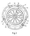
- the known diaphragm spring clutch cover assembly comprises a pressed steel cover 11 adapted to be bolted to a driving member in the form of an engineflywheel 12.
- a pressure plate 13 is driven for rotation with the cover 11 by sets of tangential straps 14 which are riveted to lugs 15 on the pressure plate 13 and to the cover 11.
- a diaphragm spring 16 is supported axially by fulcrum support means in the form of a fulcrum ring 24 on the cover side of the diaphragm spring 16, and by another fulcrum ring 21 on the opposite side of the diaphragm spring to the cover.
- the diaphragm spring has a plurality of radially inwardly directed fingers 19, adjacent fingers 19 being separated by slots 18 which terminate in windows 20 at their radially outer ends.
- GB 1 514 297 describes a method of and apparatus for assembling the sub-assembly comprising the cover 11, diaphragm spring 16 and fulcrum rings 21 and 24.
- a driven plate 22 is clamped between the engine flywheel 12 and the pressure plate 13.
- a release bearing 23 moves the radially inner ends of the fingers 19 so that the diaphragm spring pivots about the fulcrum rings 21 and 24.
- the pressure plate 13 then moves away from the flywheel 12 under the action of an axial spring load provided by the straps 14.
- the tab 17 extends axially through the window 20 and is substantially flat in this region.
- the side edges of the tab 17 extends to almost the width of the window 20 so as to contact the outer corners of the window edge and provide radial and circumferential location.
- the problem with this arrangement is that the tab locates the fulcrum rings 21 and 24 at a fulcrum radius R i which is substantially greater than the radius R 2 defining the radially outer edge of the window 20.
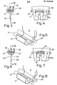
- Figs. 6, 7 and 8 show how the clutch assembly shown in Figs. 1 to 5 is modified according to the invention so that the fulcrum radius R i of the fulcrum rings 21 and 24 substantially coincides with the radius R 2 defining the radially outer edge of the window 20.
- the tab 17 has a radially outwardly deformed portion 25 over its full width in the region where is passes through the window 20.
- the deformed portions 25 locates the diaphragm spring at the radially outer corners ot the windows to provide both radial and circumferential location.
- the tab 17 has a radially outwardly deformed portion 25 A over only part of its width being half-sheared in the region where it passes through the window 20 flanked by two straight portions 26. This maintains the tensile stiffness of the tab and minimises any need to modify existing assembly methods and apparatus.
- Figs. 12,13 and 14 show how the modification of Figs. 7 and 8 can be varied so that the straight portion 26A is flanked by two radially deformed portions 25B. This has the further advantage that the diaphragm spring 16 is located at the corners of the window 20.
- Figs. 15,16 and 17 show how in a further modification the radially outwardly deformed portion 25Cof the tab 17 is formed as a dimple depression 28 on the radially inner face and a raised dome 29 on the radially outer face of said portion 25C in the region where it passes through the window 20. This avoids the ragged edges usually associated with half-sheared portions.
- Figs. 18,19 and 20 show how in a further modification the radially outwardly deformed portion 25D of the tab 17 is formed as two truncated portions 30 flanking straight portion 26B.
Landscapes
- Engineering & Computer Science (AREA)
- General Engineering & Computer Science (AREA)
- Mechanical Engineering (AREA)
- Mechanical Operated Clutches (AREA)
Applications Claiming Priority (2)
| Application Number | Priority Date | Filing Date | Title |
|---|---|---|---|
| GB8222147 | 1982-07-31 | ||
| GB8222147 | 1982-07-31 |
Publications (3)
| Publication Number | Publication Date |
|---|---|
| EP0100599A2 true EP0100599A2 (de) | 1984-02-15 |
| EP0100599A3 EP0100599A3 (en) | 1984-04-25 |
| EP0100599B1 EP0100599B1 (de) | 1986-02-12 |
Family
ID=10532043
Family Applications (1)
| Application Number | Title | Priority Date | Filing Date |
|---|---|---|---|
| EP83303783A Expired EP0100599B1 (de) | 1982-07-31 | 1983-06-30 | Tellerfederkupplungsdeckel |
Country Status (8)
| Country | Link |
|---|---|
| US (1) | US4562910A (de) |
| EP (1) | EP0100599B1 (de) |
| JP (1) | JPS5943226A (de) |
| AU (1) | AU562402B2 (de) |
| BR (1) | BR8304093A (de) |
| DE (1) | DE3362118D1 (de) |
| ES (1) | ES524568A0 (de) |
| GB (1) | GB2124312B (de) |
Cited By (1)
| Publication number | Priority date | Publication date | Assignee | Title |
|---|---|---|---|---|
| DE4420251B4 (de) * | 1993-06-23 | 2006-03-30 | Luk Lamellen Und Kupplungsbau Beteiligungs Kg | Reibungskupplung |
Families Citing this family (8)
| Publication number | Priority date | Publication date | Assignee | Title |
|---|---|---|---|---|
| JPS60138028U (ja) * | 1984-02-27 | 1985-09-12 | 株式会社 大金製作所 | クラツチのダイヤフラムスプリング支持構造 |
| JPS60145624U (ja) * | 1984-03-01 | 1985-09-27 | 株式会社 大金製作所 | クラツチのダイヤフラムスプリング支持構造 |
| JPS60252827A (ja) * | 1984-05-30 | 1985-12-13 | Daikin Mfg Co Ltd | クラツチカバ−組立体 |
| GB8514875D0 (en) * | 1985-06-12 | 1985-07-17 | Automotive Prod Plc | Clutch cover assembly |
| JPS61294221A (ja) * | 1985-06-19 | 1986-12-25 | Daikin Mfg Co Ltd | クラツチデイスク |
| JPH02174977A (ja) * | 1988-12-28 | 1990-07-06 | Nippon Oil & Fats Co Ltd | 塗装金属板の塗膜形成方法 |
| JPH0688371B2 (ja) * | 1990-05-02 | 1994-11-09 | 株式会社淀川製鋼所 | 耐久性塗装金属板 |
| DE102015204444B3 (de) * | 2015-03-12 | 2016-01-07 | Schaeffler Technologies AG & Co. KG | Druckplattenbaugruppe mit auf der Außenseite des Kupplungsdeckels angeordneter Tellerfeder |
Family Cites Families (10)
| Publication number | Priority date | Publication date | Assignee | Title |
|---|---|---|---|---|
| US2868486A (en) * | 1954-10-12 | 1959-01-13 | Illinois Tool Works | Sheet metal clip |
| DE1775115A1 (de) * | 1968-07-06 | 1971-05-19 | Luk Lamellen & Kupplungsbau | Befestigungseinrichtung fuer Abwaelzauflagen von Tellerfedern,insbesondere in Kupplungen |
| GB1347485A (en) * | 1970-07-02 | 1974-02-27 | Automotive Prod Co Ltd | Friction clutches |
| GB1514297A (en) * | 1975-10-22 | 1978-06-14 | Automotive Prod Co Ltd | Method of and apparatus for assembling a sub-assembly of a diaphragm spring clutch |
| GB2025543B (en) * | 1978-07-08 | 1983-02-02 | Automotive Prod Co Ltd | Clutch diaphragm springs |
| DE2911723A1 (de) * | 1979-03-24 | 1980-10-02 | Luk Lamellen & Kupplungsbau | Tellerfeder fuer aggregate, wie reibungskupplungen, sowie mit solchen tellerfedern ausgeruestete aggregate |
| GB2077372B (en) * | 1980-06-03 | 1983-11-23 | Automotive Prod Co Ltd | Friction clutch cover assembly |
| IT1133109B (it) * | 1980-09-18 | 1986-07-09 | Rovilmec Spa | Assieme di copertura per frizioni |
| FR2492485A1 (fr) * | 1980-10-22 | 1982-04-23 | Valeo | Mecanisme d'embrayage a diaphragme, notamment pour vehicule automobile |
| JPS5817227A (ja) * | 1981-07-24 | 1983-02-01 | Daikin Mfg Co Ltd | クラツチカバ−組立体 |
-
1983
- 1983-06-30 EP EP83303783A patent/EP0100599B1/de not_active Expired
- 1983-06-30 DE DE8383303783T patent/DE3362118D1/de not_active Expired
- 1983-07-08 US US06/511,982 patent/US4562910A/en not_active Expired - Fee Related
- 1983-07-19 GB GB08319487A patent/GB2124312B/en not_active Expired
- 1983-07-26 AU AU17289/83A patent/AU562402B2/en not_active Ceased
- 1983-07-29 BR BR8304093A patent/BR8304093A/pt unknown
- 1983-07-29 ES ES524568A patent/ES524568A0/es active Granted
- 1983-07-29 JP JP58139300A patent/JPS5943226A/ja active Pending
Cited By (1)
| Publication number | Priority date | Publication date | Assignee | Title |
|---|---|---|---|---|
| DE4420251B4 (de) * | 1993-06-23 | 2006-03-30 | Luk Lamellen Und Kupplungsbau Beteiligungs Kg | Reibungskupplung |
Also Published As
| Publication number | Publication date |
|---|---|
| DE3362118D1 (en) | 1986-03-27 |
| ES8405906A1 (es) | 1984-06-16 |
| GB8319487D0 (en) | 1983-08-17 |
| JPS5943226A (ja) | 1984-03-10 |
| AU562402B2 (en) | 1987-06-11 |
| BR8304093A (pt) | 1984-03-07 |
| GB2124312B (en) | 1985-07-31 |
| GB2124312A (en) | 1984-02-15 |
| ES524568A0 (es) | 1984-06-16 |
| AU1728983A (en) | 1984-02-02 |
| EP0100599A3 (en) | 1984-04-25 |
| EP0100599B1 (de) | 1986-02-12 |
| US4562910A (en) | 1986-01-07 |
Similar Documents
| Publication | Publication Date | Title |
|---|---|---|
| US4184578A (en) | Diaphragm spring clutches | |
| EP0114098B1 (de) | Reibungskupplung | |
| US4548306A (en) | Plate separator | |
| US5400887A (en) | Clutch cover assembly | |
| US3939951A (en) | Diaphragm clutch spring having radial and rotational restraints | |
| US4362230A (en) | Motor vehicle clutch mechanism | |
| EP0100599B1 (de) | Tellerfederkupplungsdeckel | |
| US4257510A (en) | Non-linear spring rate clutch damper | |
| US3799309A (en) | Clutch driven member assembly with vibration damper | |
| US4655334A (en) | Clutch cover and clutch cover assembly | |
| US4732252A (en) | Thrust plate unit for a friction clutch | |
| US4669592A (en) | Torsional damper device | |
| US4961486A (en) | Retainer plate of a one-way clutch assembly | |
| US4632235A (en) | Clutch with cantilevered Belleville spring | |
| US5826691A (en) | Clutch cover assembly having a diaphragm spring and a secondary biasing spring working in tandem | |
| US5265709A (en) | Pull-type clutch cover assembly | |
| GB2269641A (en) | Clutch disc assembly with lining springs | |
| EP0049058A1 (de) | Deckel für Reibungskupplung | |
| US5400888A (en) | Clutch diaphragm, in particular for a motor vehicle | |
| US5655638A (en) | Clutch module with resilient gripping of the diaphragm, and a corresponding mechanism | |
| US4607738A (en) | Friction clutch cover assemblies | |
| US4542813A (en) | Frictional clutch assembly | |
| US4365697A (en) | Friction clutch | |
| US5813507A (en) | Diaphragm clutch cover with stop lugs capable of distinguishing between different cover types | |
| EP0194001A1 (de) | Tellerfederkupplungsgehäuse |
Legal Events
| Date | Code | Title | Description |
|---|---|---|---|
| PUAI | Public reference made under article 153(3) epc to a published international application that has entered the european phase |
Free format text: ORIGINAL CODE: 0009012 |
|
| AK | Designated contracting states |
Designated state(s): BE DE FR GB IT |
|
| PUAL | Search report despatched |
Free format text: ORIGINAL CODE: 0009013 |
|
| AK | Designated contracting states |
Designated state(s): BE DE FR GB IT |
|
| 17P | Request for examination filed |
Effective date: 19840413 |
|
| ITF | It: translation for a ep patent filed | ||
| RBV | Designated contracting states (corrected) |
Designated state(s): DE FR GB IT |
|
| GRAA | (expected) grant |
Free format text: ORIGINAL CODE: 0009210 |
|
| AK | Designated contracting states |
Designated state(s): DE FR GB IT |
|
| ET | Fr: translation filed | ||
| REF | Corresponds to: |
Ref document number: 3362118 Country of ref document: DE Date of ref document: 19860327 |
|
| PLBE | No opposition filed within time limit |
Free format text: ORIGINAL CODE: 0009261 |
|
| STAA | Information on the status of an ep patent application or granted ep patent |
Free format text: STATUS: NO OPPOSITION FILED WITHIN TIME LIMIT |
|
| 26N | No opposition filed | ||
| PGFP | Annual fee paid to national office [announced via postgrant information from national office to epo] |
Ref country code: FR Payment date: 19890508 Year of fee payment: 7 |
|
| PG25 | Lapsed in a contracting state [announced via postgrant information from national office to epo] |
Ref country code: GB Effective date: 19890630 |
|
| GBPC | Gb: european patent ceased through non-payment of renewal fee | ||
| PG25 | Lapsed in a contracting state [announced via postgrant information from national office to epo] |
Ref country code: DE Effective date: 19900301 |
|
| PG25 | Lapsed in a contracting state [announced via postgrant information from national office to epo] |
Ref country code: FR Effective date: 19910228 |
|
| REG | Reference to a national code |
Ref country code: FR Ref legal event code: ST |