EP0100162A2 - Stencil duplicateur - Google Patents
Stencil duplicateur Download PDFInfo
- Publication number
- EP0100162A2 EP0100162A2 EP83303894A EP83303894A EP0100162A2 EP 0100162 A2 EP0100162 A2 EP 0100162A2 EP 83303894 A EP83303894 A EP 83303894A EP 83303894 A EP83303894 A EP 83303894A EP 0100162 A2 EP0100162 A2 EP 0100162A2
- Authority
- EP
- European Patent Office
- Prior art keywords
- stencil
- line
- heading
- image
- holes
- Prior art date
- Legal status (The legal status is an assumption and is not a legal conclusion. Google has not performed a legal analysis and makes no representation as to the accuracy of the status listed.)
- Withdrawn
Links
Images
Classifications
-
- B—PERFORMING OPERATIONS; TRANSPORTING
- B41—PRINTING; LINING MACHINES; TYPEWRITERS; STAMPS
- B41N—PRINTING PLATES OR FOILS; MATERIALS FOR SURFACES USED IN PRINTING MACHINES FOR PRINTING, INKING, DAMPING, OR THE LIKE; PREPARING SUCH SURFACES FOR USE AND CONSERVING THEM
- B41N1/00—Printing plates or foils; Materials therefor
- B41N1/24—Stencils; Stencil materials; Carriers therefor
- B41N1/248—Mechanical details, e.g. fixation holes, reinforcement or guiding means; Perforation lines; Ink holding means; Visually or otherwise detectable marking means; Stencil units
Definitions
- the present invention relates to a duplicating stencil, and in particular to the arrangement for fastening the stencil to a stencil carrier of a duplicator.
- duplicating stencils comprise limp waxy material which, when selected areas thereof are exposed to spark discharge in an electronic stencil cutter or subjected to the action of heat in a thermographic stencil maker, or stamped mechanically by the type hammer of a typewriter, becomes ink-permeable in those areas (the so-called image areas).
- image areas the so-called image areas.
- ink passes through these permeable image areas but not through the remaining impermeable non-image areas and forms, on the back of the stencil, an ink image corresponding exactly to the permeability image of the stencil. That ink image from the back of the stencil is then pressed against a sheet of paper to be deposited on the.paper as the resulting duplicated image.
- Rotary duplicators have been known for over a hundred years and in that time several characteristic patterns of mounting pins have evolved. To some extent stencils are interchangeable so that one manufacturer's stencils can be mounted on another manufacturer's duplicator, but this interchangeability is not universal.
- typing stencils have guide lines defining the areas of the stencil on which the image should be typed in order for the image to be correctly positioned on the copy sheet when that stencil is used on the duplicator for which it is intended.
- the duplicator usually has a print adjustment facility to enable the image to be moved up and/or down the copy sheet from a datum position
- the guide line is intended to enable the typist to position the image correctly for printing when the print adjustment is set at the "0" or datum position.
- U.S. Patent 4,291,621 it has been proposed that one stencil heading be formed as a plurality of separable strips each having punchings to mount the stencil on different machines of a range of duplicators, the unwanted strips being torn off before use of the stencil..
- the stencil disclosed in U.S. Patent No. 4,291,621 had to be marked with several guide lines for the typist to use when positioning the image. This has the disadvantages that the typist can easily position her image on the wrong guide line, in error, and that the typist needs to know in advance on which particular duplicator any given stencil is to be used. Since U.S. Patent No. 4,291,621 was aiming at the user who may have available various different brands of machine, the need for different guide lines was a major shortcoming which the present invention aims to overcome.
- the present invention provides a duplicating stencil for use on more than one type of duplicator, comprising a sheet of limp stencil material which is printed with markings to assist the user to position the image correctly on the stencil and has attached along one edge a stencil heading strip defined as two heading strip regions separated by an intended line of separation of the heading strip regions, each of said heading strip regions being provided with a respective array of mounting holes, said intended line of separation being parallel to and spaced from said edge of the limp sheet, characterised in that said markings define an image field based on a single top edge of the copy sheet whereby the user, when positioning the image on the stencil before printing, does not need to choose from a range of different said top edges to suit a particular duplicator type.
- At least one of the heading strip regions has more than one array of mounting holes to allow said at least one heading strip region to be attached to more than one type of duplicator.
- the demarcation line comprises a pre-scored or perforated line in the relatively stiff material of the heading strip.
- the stencil may include additional registration holes to assist the operator in correctly orienting the stencil with respect to the duplicator before attaching the stencil heading on the mounting pins.
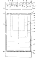
- the duplicating stencil 1 illustrated in the drawing includes a limp stencil sheet la joined along a line lb to a stiffer heading strip 2 which is defined as two separate, preferably rectangular, regions 2a and 2b.
- the stencil sheet la is printed with several grids defined by lines 10 to 17 inclusive (to be described later) to assist the typist in correctly positioning the image on the stencil.
- the region 2b includes a straight line of regularly spaced holes 3 which are spaced at the I.S.O. standard stationary spacing distance (0.5 inch between centres). Manufacturers of stencil duplicators and stencils are currently being encouraged to adopt I.S.O. spacing for the mounting pins and holes on new equipment.
- the region 2a has several different superimposed arrays of holes, the first of which comprises a line of four larger holes 4 regularly spaced along the heading strip region 2a. Preferably the spacing between these larger holes 4 is 2.6 inches between centres.
- the heading strip region 2a includes a further array of holes 5 of three different sizes and of a characteristic layout which is intended to fit a corresponding array of pins on various models of Gestetner duplicators, including the Model 466, to engage some or all of these holes but in such a way that the stencil heading strip cannot be placed on the stencil clamp inverted (i.e. with the "back" surface of the stencil in contact with the ink screen).
- the two stencil heading strip regions 2a and 2b are separated by a demarcation line 6, in this case a perforation line, which enables the region 2b to be torn from the region 2a if the various holes 4 and 5 are to be used for the mounting arrangement.
- the demarcation line 6 may instead be a pre-scored line in the stencil heading strip 2.
- the duplicator has its mounting pins at the I.S.O. spacing to conform with holes 3 of the region 2b, then that region 2b will be left attached to the region 2a and the stencil mounted in the normal way.
- the region 2a includes two further holes 7a and 7b which are coded holes to ensure that, when using the regularly spaced holes 3 of region 2b or the regularly spaced holes 4 of region 2a, the stencil is not placed inverted. For this reason the lefthand hole 7a is of rectangular form and is generally larger than the righthand hole 7b of circular form.
- This coding of the stencil heading strip enables it to be used with a stencil loading device in accordance with our U.K. Patent Application Noo 8218196 (Specification No. ).
- the configuration shown in the drawing may be modified by providing more than two such heading strip regions, for maximum versatility of the stencil.
- the image field based on the single "top edge paper guide” line 8 is defined by a large rectangular grid 10 having a length of 317 mm (measured in a direction perpendicular to the "top edge paper guide” line 8) and a width of 210 mm (measured in a direction parallel to the "top edge paper guide” line 8).
- the upper transverse edge of the grid 10 (the one closer to the guide line 8) is spaced from the line 8 by a distance of 13 mm. This is to allow for clamping means on the duplicator to pick up the copy sheet and carry it through the printing nip between the cylinder and an impression roll and consequently it is intended that there should be no image in that particular 13 mm wide strip across the top of the copy sheet.
- the overall width of the grid 10 is equivalent to the width of an A4 sheet, and the grid 10 is positioned with its bottom transverse edge spaced from the line 8 by the length of a legal foolscap sheet (33D mm).
- the centrally arranged small grid 11 in the image field corresponds to an A6 copy sheet extending lengthwise of the stencil.
- the grid 12 indicates the positioning of an A6 sheet positioned transversely across the stencil.
- the medium-sized grid 13 represents the arrangement of an A5 sheet lengthwise of the stencil while the grid 14 illustrates the positioning of an A5 sheet transversely across the stencil.
- the line 15 marks the bottom of a 10 inch copy sheet (254 mm in length) whereas the line 16 depicts the bottom edge of an A4 sheet.
- corner markings 17 illustrate the bottom corners of a sheet measuring 8 inches by 5 inches (204 mm by 127 mm).
- each of these grids is based on the common "top edge paper guide" line 8 as in the case of a conventional stencil.
- the stencil in accordance with the present invention presents no undue problems as he or she simply aligns the image with whichever of the various copy sheet size grids would be used on a conventional stencil.
- This is considered a very important advantage of the multi-heading stencil according to the present invention and provides for the possibility of having all stencils typed without any reference to the particular heading strip 2a or 2b which is to be used to mount the stencil on a duplicator, so that once that stencil is to be printed the user of the duplicator simply takes up any image mispositioning by use of the normal print adjustment control on the duplicator.
- the stencils may all be in accordance with the present invention and thus, once the print adjustment of any one of those duplicators has been set for the stencil in accordance with the invention there is no need for further adjustment provided (as with a conventional single heading stencil) the typist correctly positions the image with reference to the guide line 8 by using the appropriate positioning grid 10, 11, 12, 13 or 14. All the operator needs to be careful of is that he or she tears off the strip 2b, or not as the case may be, and uses the line of mounting holes 3 or 4, 5 appropriate to the particular duplicator being used.
- the optimum position for the stencil on the ink screen is a function of the design of the stencil clamp, and the optimum position of the image on the stencil is furthermore dictated by the copy sheet gripper system on the impression roll, it turns out in practice that the "zero" position of the print adjustment is not in the centre of the range. In fact it is possible, given a stencil which has the image based on the "top edge paper guide” line 8 for the stencil to be adjusted upwardly by 3.9 cm (9 lines of print) or downwardly by 1.3 cm (3 lines of print).
Landscapes
- Engineering & Computer Science (AREA)
- Mechanical Engineering (AREA)
- Printing Plates And Materials Therefor (AREA)
- Manufacture Or Reproduction Of Printing Formes (AREA)
Applications Claiming Priority (5)
| Application Number | Priority Date | Filing Date | Title |
|---|---|---|---|
| GB8221249 | 1982-07-22 | ||
| GB8221249 | 1982-07-22 | ||
| GB8221317 | 1982-07-23 | ||
| GB08231257A GB2124149B (en) | 1982-07-22 | 1982-11-02 | Duplicating stencil |
| GB8231257 | 1982-11-02 |
Publications (2)
| Publication Number | Publication Date |
|---|---|
| EP0100162A2 true EP0100162A2 (fr) | 1984-02-08 |
| EP0100162A3 EP0100162A3 (fr) | 1985-05-15 |
Family
ID=27261676
Family Applications (1)
| Application Number | Title | Priority Date | Filing Date |
|---|---|---|---|
| EP83303894A Withdrawn EP0100162A3 (fr) | 1982-07-22 | 1983-07-04 | Stencil duplicateur |
Country Status (1)
| Country | Link |
|---|---|
| EP (1) | EP0100162A3 (fr) |
Family Cites Families (5)
| Publication number | Priority date | Publication date | Assignee | Title |
|---|---|---|---|---|
| FR320615A (fr) * | 1902-04-23 | 1902-12-16 | Klaber Agustus David | Perfectionnements relatifs aux feuilles clichés et à leur mode de fixation sur les duplicateurs |
| GB450223A (en) * | 1935-01-16 | 1936-07-13 | Reginald George Pluckrose | Improvements relating to stencil paper for use on rotary and other duplicators |
| US2177768A (en) * | 1937-12-21 | 1939-10-31 | Henry M Carscallen | Stencil sheet |
| US2201953A (en) * | 1939-08-03 | 1940-05-21 | Remington Rand Inc | Top printed stencil and method of making |
| US4291621A (en) * | 1978-09-25 | 1981-09-29 | Thomas Charles F | Adaptable stencil for different mimeograph machines |
-
1983
- 1983-07-04 EP EP83303894A patent/EP0100162A3/fr not_active Withdrawn
Also Published As
| Publication number | Publication date |
|---|---|
| EP0100162A3 (fr) | 1985-05-15 |
Similar Documents
| Publication | Publication Date | Title |
|---|---|---|
| US4515077A (en) | Duplicating stencil | |
| US2680405A (en) | Method for preregistering color plates | |
| US5337669A (en) | Card printing method, original positioning holder, and card printing paper | |
| DE58909200D1 (de) | Vorrichtung zur Passerkorrektur der Bogenaufdrucke in einer Bogenrotationsdruckmaschine. | |
| EP0364424A3 (fr) | Procédé d'ajustage d'une impression dans une position d'impression respective dans des machines de sérigraphie en plusieurs couleurs | |
| EP0100162A2 (fr) | Stencil duplicateur | |
| GB2124149A (en) | Duplicating stencil | |
| US4291621A (en) | Adaptable stencil for different mimeograph machines | |
| JPH0739663Y2 (ja) | 押圧式孔版印刷装置 | |
| US2070181A (en) | Stencil sheet | |
| US2201953A (en) | Top printed stencil and method of making | |
| JPH11227163A (ja) | 印刷方法 | |
| JP2980249B2 (ja) | 孔版原紙セット方法 | |
| US3982743A (en) | Method of manufacturing books | |
| US1861260A (en) | Stenciling material | |
| US4807907A (en) | Article of stationery | |
| JPH0712002Y2 (ja) | プリンタ装置 | |
| EP0553626A1 (fr) | Procédé d'impression typographique et dispositif pour la mise en oeuvre de ce procédé | |
| JPS5933195A (ja) | 複写ステンシル | |
| JPH0318207Y2 (fr) | ||
| JP2525289Y2 (ja) | 孔版印刷の補助用具 | |
| CA1242111A (fr) | Dispositif de reperage des pellicules pour la production de plaques d'impression sur petites machines offset | |
| JPH0310877A (ja) | ページプリンタ | |
| JPH0547656Y2 (fr) | ||
| US1575718A (en) | Stencil sheet for rotary duplicating machines |
Legal Events
| Date | Code | Title | Description |
|---|---|---|---|
| PUAI | Public reference made under article 153(3) epc to a published international application that has entered the european phase |
Free format text: ORIGINAL CODE: 0009012 |
|
| AK | Designated contracting states |
Designated state(s): AT BE CH DE FR IT LI NL SE |
|
| PUAL | Search report despatched |
Free format text: ORIGINAL CODE: 0009013 |
|
| AK | Designated contracting states |
Designated state(s): AT BE CH DE FR IT LI NL SE |
|
| 17P | Request for examination filed |
Effective date: 19850503 |
|
| 17Q | First examination report despatched |
Effective date: 19860801 |
|
| STAA | Information on the status of an ep patent application or granted ep patent |
Free format text: STATUS: THE APPLICATION HAS BEEN WITHDRAWN |
|
| 18W | Application withdrawn |
Withdrawal date: 19861216 |
|
| RIN1 | Information on inventor provided before grant (corrected) |
Inventor name: LYTRA, ERIC KYBROS Inventor name: DAVIDSON, LEWIS Inventor name: LEES, BRIAN |