EP0099807B1 - Circuit de commande de l'arrêt d'appareils, notamment de moyens d'éclairage - Google Patents
Circuit de commande de l'arrêt d'appareils, notamment de moyens d'éclairage Download PDFInfo
- Publication number
- EP0099807B1 EP0099807B1 EP83401404A EP83401404A EP0099807B1 EP 0099807 B1 EP0099807 B1 EP 0099807B1 EP 83401404 A EP83401404 A EP 83401404A EP 83401404 A EP83401404 A EP 83401404A EP 0099807 B1 EP0099807 B1 EP 0099807B1
- Authority
- EP
- European Patent Office
- Prior art keywords
- relay
- remote control
- circuit
- control means
- circuit according
- Prior art date
- Legal status (The legal status is an assumption and is not a legal conclusion. Google has not performed a legal analysis and makes no representation as to the accuracy of the status listed.)
- Expired
Links
- 230000007935 neutral effect Effects 0.000 claims description 4
- 230000008033 biological extinction Effects 0.000 description 5
- 238000009434 installation Methods 0.000 description 5
- 238000000429 assembly Methods 0.000 description 3
- 238000010586 diagram Methods 0.000 description 3
- 230000000694 effects Effects 0.000 description 2
- 238000004378 air conditioning Methods 0.000 description 1
- 230000000712 assembly Effects 0.000 description 1
- 238000009826 distribution Methods 0.000 description 1
- 238000005304 joining Methods 0.000 description 1
- 238000012423 maintenance Methods 0.000 description 1
- 238000004519 manufacturing process Methods 0.000 description 1
- 238000003825 pressing Methods 0.000 description 1
- 230000000284 resting effect Effects 0.000 description 1
- 230000001360 synchronised effect Effects 0.000 description 1
Images


Classifications
-
- H—ELECTRICITY
- H01—ELECTRIC ELEMENTS
- H01H—ELECTRIC SWITCHES; RELAYS; SELECTORS; EMERGENCY PROTECTIVE DEVICES
- H01H47/00—Circuit arrangements not adapted to a particular application of the relay and designed to obtain desired operating characteristics or to provide energising current
-
- H—ELECTRICITY
- H02—GENERATION; CONVERSION OR DISTRIBUTION OF ELECTRIC POWER
- H02J—CIRCUIT ARRANGEMENTS OR SYSTEMS FOR SUPPLYING OR DISTRIBUTING ELECTRIC POWER; SYSTEMS FOR STORING ELECTRIC ENERGY
- H02J13/00—Circuit arrangements for providing remote indication of network conditions, e.g. an instantaneous record of the open or closed condition of each circuitbreaker in the network; Circuit arrangements for providing remote control of switching means in a power distribution network, e.g. switching in and out of current consumers by using a pulse code signal carried by the network
- H02J13/00006—Circuit arrangements for providing remote indication of network conditions, e.g. an instantaneous record of the open or closed condition of each circuitbreaker in the network; Circuit arrangements for providing remote control of switching means in a power distribution network, e.g. switching in and out of current consumers by using a pulse code signal carried by the network characterised by information or instructions transport means between the monitoring, controlling or managing units and monitored, controlled or operated power network element or electrical equipment
- H02J13/00012—Circuit arrangements for providing remote indication of network conditions, e.g. an instantaneous record of the open or closed condition of each circuitbreaker in the network; Circuit arrangements for providing remote control of switching means in a power distribution network, e.g. switching in and out of current consumers by using a pulse code signal carried by the network characterised by information or instructions transport means between the monitoring, controlling or managing units and monitored, controlled or operated power network element or electrical equipment using an auxiliary transmission line
-
- H—ELECTRICITY
- H02—GENERATION; CONVERSION OR DISTRIBUTION OF ELECTRIC POWER
- H02J—CIRCUIT ARRANGEMENTS OR SYSTEMS FOR SUPPLYING OR DISTRIBUTING ELECTRIC POWER; SYSTEMS FOR STORING ELECTRIC ENERGY
- H02J13/00—Circuit arrangements for providing remote indication of network conditions, e.g. an instantaneous record of the open or closed condition of each circuitbreaker in the network; Circuit arrangements for providing remote control of switching means in a power distribution network, e.g. switching in and out of current consumers by using a pulse code signal carried by the network
- H02J13/00032—Systems characterised by the controlled or operated power network elements or equipment, the power network elements or equipment not otherwise provided for
- H02J13/00036—Systems characterised by the controlled or operated power network elements or equipment, the power network elements or equipment not otherwise provided for the elements or equipment being or involving switches, relays or circuit breakers
-
- H—ELECTRICITY
- H05—ELECTRIC TECHNIQUES NOT OTHERWISE PROVIDED FOR
- H05B—ELECTRIC HEATING; ELECTRIC LIGHT SOURCES NOT OTHERWISE PROVIDED FOR; CIRCUIT ARRANGEMENTS FOR ELECTRIC LIGHT SOURCES, IN GENERAL
- H05B47/00—Circuit arrangements for operating light sources in general, i.e. where the type of light source is not relevant
- H05B47/10—Controlling the light source
-
- Y—GENERAL TAGGING OF NEW TECHNOLOGICAL DEVELOPMENTS; GENERAL TAGGING OF CROSS-SECTIONAL TECHNOLOGIES SPANNING OVER SEVERAL SECTIONS OF THE IPC; TECHNICAL SUBJECTS COVERED BY FORMER USPC CROSS-REFERENCE ART COLLECTIONS [XRACs] AND DIGESTS
- Y02—TECHNOLOGIES OR APPLICATIONS FOR MITIGATION OR ADAPTATION AGAINST CLIMATE CHANGE
- Y02B—CLIMATE CHANGE MITIGATION TECHNOLOGIES RELATED TO BUILDINGS, e.g. HOUSING, HOUSE APPLIANCES OR RELATED END-USER APPLICATIONS
- Y02B70/00—Technologies for an efficient end-user side electric power management and consumption
- Y02B70/30—Systems integrating technologies related to power network operation and communication or information technologies for improving the carbon footprint of the management of residential or tertiary loads, i.e. smart grids as climate change mitigation technology in the buildings sector, including also the last stages of power distribution and the control, monitoring or operating management systems at local level
-
- Y—GENERAL TAGGING OF NEW TECHNOLOGICAL DEVELOPMENTS; GENERAL TAGGING OF CROSS-SECTIONAL TECHNOLOGIES SPANNING OVER SEVERAL SECTIONS OF THE IPC; TECHNICAL SUBJECTS COVERED BY FORMER USPC CROSS-REFERENCE ART COLLECTIONS [XRACs] AND DIGESTS
- Y04—INFORMATION OR COMMUNICATION TECHNOLOGIES HAVING AN IMPACT ON OTHER TECHNOLOGY AREAS
- Y04S—SYSTEMS INTEGRATING TECHNOLOGIES RELATED TO POWER NETWORK OPERATION, COMMUNICATION OR INFORMATION TECHNOLOGIES FOR IMPROVING THE ELECTRICAL POWER GENERATION, TRANSMISSION, DISTRIBUTION, MANAGEMENT OR USAGE, i.e. SMART GRIDS
- Y04S20/00—Management or operation of end-user stationary applications or the last stages of power distribution; Controlling, monitoring or operating thereof
- Y04S20/20—End-user application control systems
- Y04S20/242—Home appliances
- Y04S20/246—Home appliances the system involving the remote operation of lamps or lighting equipment
Definitions
- the present invention relates to a device stop control circuit. It finds an application in particular in the production of programmable remote lighting extinguishing systems which the inventor designates under the acronym SPEED.
- the circuit of the invention is particularly well suited to systems intended to save the electrical energy consumed by artificial light sources (bulbs, luminescent tubes, projectors, etc.). It can be used advantageously in installations comprising a large number of autonomous lighting sub-assemblies.
- Publication DE-C N ° 931902 shows a control circuit for stopping devices, each device being provided with a switch, which comprises at least one contact and is associated with at least one push-button capable of doing so. alternately switch to the open position and the closed position.
- the circuit includes an additional switch control member, functionally equivalent to the push button but controlled by a remote control means allowing the devices to be stopped and restarted.
- Publication DE-A N ° 2816876 shows a similar circuit, the remote control means of which only allows the devices to be stopped.
- the device of the invention differs from known circuits in that the additional switch control member is controlled by a relay arranged in series with one of the switch contacts to disconnect this relay from the network. power supply after actuation of the remote control means. Because the switch contacts are synchronized, control of the relay is impossible if the switch is in the open position.
- the remote control means are thus unable to return a stopped device to service. This return to service can only be carried out using the device-specific pushbuttons.
- the device of the invention adapts very well to the switching rooms of large telephone exchanges comprising a large number of sectoral bay lights; but it is also suitable for sets of offices, workshops, warehouses, living quarters, etc.
- the device of the invention also applies to bodies other than lighting means, such as engines, radiators, fans, air conditioning devices, machines, various equipment.
- the energy necessary for the power supply can come from any network: mono, bi or three-phase, low or high voltage, alternating or direct.
- the invention also applies to the control of devices supplied with energy other than electrical, for example pneumatic or hydraulic.
- the circuit of the invention allows a saving of material by reducing the times of use thereof and a saving of manpower by reducing maintenance costs.
- the device shown in fig. 1 comprises an apparatus 10 of any type connected to an electrical power source 12 via a contact 14 belonging to a switch 16.
- the latter is powered by a source 18 and controlled by a push button 20. Pressing this button successively causes the switch to open and close, thus stopping and putting the device 10 into service.
- the device further comprises an additional member 22 for controlling the switch 16, this member being functionally equivalent to the push button evening 20, in that it causes the closing or opening of the switch 16.
- the member 22 is actuated by a relay 24 arranged in series with a contact 26 belonging to the switch 16 and controlled in synchronism with the contact 14. Furthermore, the relay 24 is supplied by a source 28 and remotely controlled by a means 30.
- the push button 20 constitutes a control member which is specific to the apparatus 10. It makes it possible to put this apparatus into service or to put it to a standstill. In service, the two contacts 14 and 26 are closed. When stopped, they are both open. Assuming that the apparatus 10 is in operation, an action on the switch 16 causes the apparatus to stop. This action can be accomplished either by the push button 20 or by the member 22. In the first case, it is a manual extinction performed by the operator. In the second, it is a centralized remote control. To do this, it suffices to close the means 30, which excites the relay 24 and causes the contact 14 to open, thus stopping the device 10.
- the contact 26 is open, so that it is no longer possible to act on the relay 24 and therefore on the member 22. This means that the remote control means 30 cannot ensure delivery. in operation of the apparatus 10. This can only be obtained by the control means specific to the switch 16, that is to say, in this case, by action on the push button 20.
- closing the contact 30 makes it possible to remotely control the stopping of the apparatus 10 if it is in service, but has no effect on the installation if the apparatus is at stop.
- the power supply means 28 and the remote control means 30 are common to a certain number of sub-assemblies each having a relay 24, 24 ', 24 "... mounted in series with a contact of the switch specific to this Closing the contact 30 then causes all the devices in service in these subassemblies to stop but has no effect on the devices that are stopped.
- the contacts 14 and 26 can be combined as illustrated in FIG. 8.
- the switch 16 is of the remote control type and makes it possible to control a device by means of several push buttons distributed in different places.
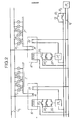
- Fig. 2 firstly represents two sets E and E 'of lighting lamps 10 1 , 10 2 , 10 3 ... and 10' 1 , 10 ' Z , 10' 3 ... supplied respectively by remote control switches 16 , 16 'of which a contact 14, 14' is in series with a supply line supplying a voltage V 1 .
- the remote control switches are each controlled by two push-buttons 201, 20 2 and 20 ' 1 , 20' 2 and by an additional contact 22, 22 'controlled by a relay 24, 24'.
- This relay is in series with one of the contacts 26, 26 'of the remote control switch.
- a power supply 28 delivers a voltage V 2 which is used both for the remote switches 16 and 16 'and for the relays 24 and 24'.
- the relay control means include a contact 30, with programmable control and a push button 30 2 with manual control.
- the contact 30 can be controlled by a clock, by a photodetector or by any other means depending on the conditions of use.
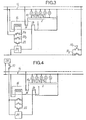
- the diagram in fig. 3 does not differ from that of FIG. 2 only by the fact that the remote control switch 16 and the relay 24 are no longer supplied from an independent source but from the voltage V, supplying the lamps.
- the voltage applied to the relay 24 results from the superposition of the voltage delivered by the source 28 and the supply voltage of the lamps.
- the voltage delivered by the source 28 has a particular characteristic to which the relay is sensitive. It may be a voltage in the form of short pulses, or a voltage having an appropriate frequency. Another possibility is to interrupt the supply voltage V 1 using its own switch according to a predetermined code recognized by the relay.
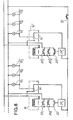
- Fig. 5 shows a variant in which the electrical supply installation is three-phase.
- the remote control switch then includes one contact per phase, ie 3 contacts 14 1 , 14 z , 14 3 to which is added a contact M 4 for the neutral when necessary (line N in dashes).
- the device to be powered is in this case a set of lamps 10 on the left part and an electric motor 10 'mounted in a triangle on the right part.
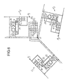
- Fig. 6 also relates to a three-phase installation but with an N neutral removed.
- the three phases P 1 , P 2 , P 3 supply three lighting assemblies E,, E 2 , E 3 .
- the programmable control contacts 30 1 and manual control 30 2 are this time triple contacts associated with the three phases.
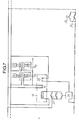
- Fig. 7 illustrates a variant in which the device to be controlled is a member 50 associated with a switch 52 with two stop-on positions.
- the stop control circuit is still composed of a relay 24 and a contact 26, but this time acts on the switch 52 and not directly on the device 50.
- the latter is supplied by a source of energy 54 of any kind (electrical, hydraulic, etc.).
- the device 50 can therefore be an engine, a radiator, a chiller, a heat pump, etc.
- fig. 8 illustrates a variant characterized by the fact that the contact of the switch which controls the supply of the devices for which the stop is to be controlled is placed in series with the remote control circuit 30, the single contact 14 'joining the times the contacts 14 and 26 of the previous variants.
- the remote control means 30 can take a wide variety of forms: it can simply be a push button that the operator actuates as he pleases, for example at the end of the day or during off-peak hours ; but it can also be an automatic means using a detector determining the instant suitable for extinction. In the case of application to lighting installations, this detector can be a photodetector sensitive to ambient light and which controls the extinction of the lamps when natural lighting makes artificial lighting unnecessary.
- the lamp supply network is not interrupted, but only returned to a resting state from which each lamp can be switched on again independently.
Landscapes
- Engineering & Computer Science (AREA)
- Power Engineering (AREA)
- Remote Monitoring And Control Of Power-Distribution Networks (AREA)
- Selective Calling Equipment (AREA)
- Keying Circuit Devices (AREA)
Applications Claiming Priority (2)
| Application Number | Priority Date | Filing Date | Title |
|---|---|---|---|
| FR8212185 | 1982-07-12 | ||
| FR8212185A FR2530091A1 (fr) | 1982-07-12 | 1982-07-12 | Circuit de commande de l'arret d'appareils, utilisable notamment pour l'extinction de moyens d'eclairage |
Publications (2)
| Publication Number | Publication Date |
|---|---|
| EP0099807A1 EP0099807A1 (fr) | 1984-02-01 |
| EP0099807B1 true EP0099807B1 (fr) | 1986-04-02 |
Family
ID=9275909
Family Applications (1)
| Application Number | Title | Priority Date | Filing Date |
|---|---|---|---|
| EP83401404A Expired EP0099807B1 (fr) | 1982-07-12 | 1983-07-07 | Circuit de commande de l'arrêt d'appareils, notamment de moyens d'éclairage |
Country Status (4)
| Country | Link |
|---|---|
| US (1) | US4591731A (enExample) |
| EP (1) | EP0099807B1 (enExample) |
| DE (1) | DE3362781D1 (enExample) |
| FR (1) | FR2530091A1 (enExample) |
Families Citing this family (12)
| Publication number | Priority date | Publication date | Assignee | Title |
|---|---|---|---|---|
| US4833339A (en) * | 1983-10-13 | 1989-05-23 | Lutron Electronics Co., Inc. | Load control system |
| JPH0195306A (ja) * | 1987-10-07 | 1989-04-13 | Fanuc Ltd | 非常停止制御回路 |
| US4841162A (en) * | 1988-07-14 | 1989-06-20 | Lay Bor Cherng | Limiter switching apparatus |
| FR2653592B1 (fr) * | 1989-10-20 | 1991-12-20 | Merlin Gerin | Dispositif de commande d'un telerupteur. |
| US5191227A (en) * | 1990-06-29 | 1993-03-02 | Digital Equipment Corporation | Apparatus for transferring control of a plurality of electrical devices upon interconnection |
| FR2705840B1 (fr) * | 1993-05-27 | 1995-07-07 | Gestra | Système de délestage électrique. |
| US5532675A (en) * | 1994-12-29 | 1996-07-02 | Linda Johnson | Alarm tester |
| FR2753311B1 (fr) * | 1996-09-12 | 1998-11-27 | Merx Philippe | Dispostiif electrique dont les organes de commande et les appareils commandes sont mobiles |
| FR2753312B3 (fr) * | 1996-09-12 | 1998-11-13 | Merx Philippe | Dispositif electrique dont les organes de commande et les appareils commandes sont mobiles |
| FR2775360B1 (fr) * | 1998-02-26 | 2000-04-14 | Alpes Systeme Automation | Dispositif auxiliaire de commande d'au moins un organe fonctionnel a commande electrique |
| IT1305168B1 (it) * | 1998-11-06 | 2001-04-10 | Massimo Catena | Dispositivo di comando di utilizzatori elettrici con funzione di resete impianto elettrico utilizzante tale dispositivo di comando |
| US7064502B2 (en) * | 2002-11-22 | 2006-06-20 | Black & Decker Inc. | Power tool with remote stop |
Family Cites Families (7)
| Publication number | Priority date | Publication date | Assignee | Title |
|---|---|---|---|---|
| DE931902C (de) * | 1949-04-09 | 1955-08-18 | Siemens Ag | Schaltungsanordnung zur elektrischen Fernsteuerung mehrerer gruppenweise ein- und ausschaltbarer Stromverbraucher |
| DE956783C (de) * | 1950-11-02 | 1957-01-24 | Licentia Gmbh | Impulssteuerung fuer ferngesteuerte Schuetze und Schalter |
| US3514626A (en) * | 1968-10-16 | 1970-05-26 | George E Platzer Jr | Switching circuit |
| US4101786A (en) * | 1976-06-14 | 1978-07-18 | Clemar Manufacturing Corporation | Master-satellite irrigation control system with remote proportional timing |
| US4208593A (en) * | 1978-02-13 | 1980-06-17 | U.S. Energy Conservation Systems, Inc. | Method and system of selective disconnection of loads from a power source |
| DE2816876A1 (de) * | 1978-04-18 | 1979-10-25 | Ulrich Werning | Schaltungsanordnung zur zentralen steuerung von lastkreisen, insbesondere zur steuerung von beleuchtungszonen in gebaeuden |
| US4378507A (en) * | 1980-12-22 | 1983-03-29 | Root Robert H | Emergency power shutdown system for educational laboratory |
-
1982
- 1982-07-12 FR FR8212185A patent/FR2530091A1/fr active Granted
-
1983
- 1983-07-07 DE DE8383401404T patent/DE3362781D1/de not_active Expired
- 1983-07-07 EP EP83401404A patent/EP0099807B1/fr not_active Expired
- 1983-07-11 US US06/508,117 patent/US4591731A/en not_active Expired - Lifetime
Also Published As
| Publication number | Publication date |
|---|---|
| FR2530091B1 (enExample) | 1984-11-30 |
| DE3362781D1 (en) | 1986-05-07 |
| FR2530091A1 (fr) | 1984-01-13 |
| US4591731A (en) | 1986-05-27 |
| EP0099807A1 (fr) | 1984-02-01 |
Similar Documents
| Publication | Publication Date | Title |
|---|---|---|
| EP0099807B1 (fr) | Circuit de commande de l'arrêt d'appareils, notamment de moyens d'éclairage | |
| CA1320754C (fr) | Systeme et dispositif de commande pour appareil contacteur | |
| US4825096A (en) | Remote control apparatus for tripping off switches | |
| FR2717599A1 (fr) | Circuit pour une installation comportant un élément pouvant fonctionner de façon intermittente, notamment une installation à feux clignotants d'avertissement de véhicule automobile. | |
| FR2571186A1 (fr) | Procede et dispositif de commande d'un moteur electrique a alimentation triphasee | |
| EP0395553B1 (fr) | Ensemble composé d'un circuit électrique pour hotte aspirante et d'un circuit électrique pour poste de cuisson | |
| EP1227590B1 (fr) | Procédé et dispositif d'élaboration d'une tension d'alimentation nécessaire au pilotage d'un interrupteur électronique | |
| US3603807A (en) | Timeclock dimming control | |
| US1783634A (en) | Control mechanism for electric motors | |
| FR2597917A1 (fr) | Procede pour commander des instruments associes d'un systeme de porte automatique | |
| JPS5910914Y2 (ja) | 電気機器状態表示回路 | |
| EP0847229B1 (fr) | Dispositif commutateur-variateur pour réseaux électriques | |
| FR2631138A1 (fr) | Dispositif de controle du demarrage d'une machine dangereuse et de protection au voisinage d'une telle machine et procede de demarrage d'une telle machine | |
| FR2492062A1 (fr) | Procede et dispositif pour la regulation automatique du debit de la ventilation mecanique controlee d'une installation de chauffage electrique integre | |
| JPS63126194A (ja) | 遅延消灯装置付照明器具 | |
| FR3076392A1 (fr) | Systeme de commande electrique comportant plusieurs points de commande et appareillage electrique mis en œuvre dans un tel systeme de commande | |
| EP0399983B1 (fr) | Dispositif d'arrêt d'urgence pour installation industrielle | |
| FR2763465A1 (fr) | Dispositif d'alimentation pour un appareil d'eclairage utilisant une ou plusieurs lampes a decharge | |
| FR2540305A1 (en) | Remote control device for at least one security unit | |
| US3619520A (en) | Ballast circuit and switch therefor | |
| JPS6331193Y2 (enExample) | ||
| EP2663166B1 (fr) | Commutation sans fil d'un circuit d'excitation d'un appareil central du type minuterie, télérupteur ou gradateur | |
| BE1001384A7 (fr) | Perfectionnement d'une minuterie electrique. | |
| US2329103A (en) | Fluorescent lamp switch | |
| JP2000041342A (ja) | バッテリ用電気回路 |
Legal Events
| Date | Code | Title | Description |
|---|---|---|---|
| PUAI | Public reference made under article 153(3) epc to a published international application that has entered the european phase |
Free format text: ORIGINAL CODE: 0009012 |
|
| AK | Designated contracting states |
Designated state(s): DE GB IT NL SE |
|
| 17P | Request for examination filed |
Effective date: 19840718 |
|
| GRAA | (expected) grant |
Free format text: ORIGINAL CODE: 0009210 |
|
| AK | Designated contracting states |
Kind code of ref document: B1 Designated state(s): DE GB IT NL SE |
|
| REF | Corresponds to: |
Ref document number: 3362781 Country of ref document: DE Date of ref document: 19860507 |
|
| ITF | It: translation for a ep patent filed | ||
| PLBE | No opposition filed within time limit |
Free format text: ORIGINAL CODE: 0009261 |
|
| STAA | Information on the status of an ep patent application or granted ep patent |
Free format text: STATUS: NO OPPOSITION FILED WITHIN TIME LIMIT |
|
| 26N | No opposition filed | ||
| ITTA | It: last paid annual fee | ||
| EAL | Se: european patent in force in sweden |
Ref document number: 83401404.5 |
|
| PGFP | Annual fee paid to national office [announced via postgrant information from national office to epo] |
Ref country code: GB Payment date: 19970624 Year of fee payment: 15 |
|
| PGFP | Annual fee paid to national office [announced via postgrant information from national office to epo] |
Ref country code: SE Payment date: 19970625 Year of fee payment: 15 |
|
| PGFP | Annual fee paid to national office [announced via postgrant information from national office to epo] |
Ref country code: DE Payment date: 19970704 Year of fee payment: 15 |
|
| PGFP | Annual fee paid to national office [announced via postgrant information from national office to epo] |
Ref country code: NL Payment date: 19970731 Year of fee payment: 15 |
|
| PG25 | Lapsed in a contracting state [announced via postgrant information from national office to epo] |
Ref country code: GB Free format text: LAPSE BECAUSE OF NON-PAYMENT OF DUE FEES Effective date: 19980707 |
|
| PG25 | Lapsed in a contracting state [announced via postgrant information from national office to epo] |
Ref country code: SE Free format text: LAPSE BECAUSE OF NON-PAYMENT OF DUE FEES Effective date: 19980708 |
|
| PG25 | Lapsed in a contracting state [announced via postgrant information from national office to epo] |
Ref country code: NL Free format text: LAPSE BECAUSE OF NON-PAYMENT OF DUE FEES Effective date: 19990201 |
|
| GBPC | Gb: european patent ceased through non-payment of renewal fee |
Effective date: 19980707 |
|
| EUG | Se: european patent has lapsed |
Ref document number: 83401404.5 |
|
| NLV4 | Nl: lapsed or anulled due to non-payment of the annual fee |
Effective date: 19990201 |
|
| PG25 | Lapsed in a contracting state [announced via postgrant information from national office to epo] |
Ref country code: DE Free format text: LAPSE BECAUSE OF NON-PAYMENT OF DUE FEES Effective date: 19990501 |