EP0099154B1 - Obturateur photographique à rideaux - Google Patents
Obturateur photographique à rideaux Download PDFInfo
- Publication number
- EP0099154B1 EP0099154B1 EP83201008A EP83201008A EP0099154B1 EP 0099154 B1 EP0099154 B1 EP 0099154B1 EP 83201008 A EP83201008 A EP 83201008A EP 83201008 A EP83201008 A EP 83201008A EP 0099154 B1 EP0099154 B1 EP 0099154B1
- Authority
- EP
- European Patent Office
- Prior art keywords
- pinion
- rotation
- drum
- spindle
- chassis
- Prior art date
- Legal status (The legal status is an assumption and is not a legal conclusion. Google has not performed a legal analysis and makes no representation as to the accuracy of the status listed.)
- Expired
Links
- 230000007246 mechanism Effects 0.000 claims description 31
- 238000013519 translation Methods 0.000 claims description 12
- 238000011084 recovery Methods 0.000 claims description 5
- 238000006073 displacement reaction Methods 0.000 claims description 4
- 238000004804 winding Methods 0.000 claims description 4
- 238000003780 insertion Methods 0.000 claims description 3
- 230000037431 insertion Effects 0.000 claims description 3
- RTAQQCXQSZGOHL-UHFFFAOYSA-N Titanium Chemical compound [Ti] RTAQQCXQSZGOHL-UHFFFAOYSA-N 0.000 claims description 2
- 238000003825 pressing Methods 0.000 claims description 2
- 239000010935 stainless steel Substances 0.000 claims description 2
- 229910001220 stainless steel Inorganic materials 0.000 claims description 2
- 239000010936 titanium Substances 0.000 claims description 2
- 229910052719 titanium Inorganic materials 0.000 claims description 2
- XEEYBQQBJWHFJM-UHFFFAOYSA-N Iron Chemical compound [Fe] XEEYBQQBJWHFJM-UHFFFAOYSA-N 0.000 claims 1
- 238000001514 detection method Methods 0.000 claims 1
- 230000003100 immobilizing effect Effects 0.000 claims 1
- 229910052751 metal Inorganic materials 0.000 description 5
- 239000002184 metal Substances 0.000 description 5
- 238000004873 anchoring Methods 0.000 description 4
- 230000009471 action Effects 0.000 description 3
- 230000008901 benefit Effects 0.000 description 3
- 230000007704 transition Effects 0.000 description 3
- 230000001133 acceleration Effects 0.000 description 2
- 238000012163 sequencing technique Methods 0.000 description 2
- 239000007787 solid Substances 0.000 description 2
- 230000002411 adverse Effects 0.000 description 1
- 230000002238 attenuated effect Effects 0.000 description 1
- 230000008859 change Effects 0.000 description 1
- 238000010276 construction Methods 0.000 description 1
- 230000008602 contraction Effects 0.000 description 1
- 230000003247 decreasing effect Effects 0.000 description 1
- 238000010586 diagram Methods 0.000 description 1
- 230000000694 effects Effects 0.000 description 1
- 239000013013 elastic material Substances 0.000 description 1
- 238000005265 energy consumption Methods 0.000 description 1
- 238000009499 grossing Methods 0.000 description 1
- 238000005286 illumination Methods 0.000 description 1
- 230000006872 improvement Effects 0.000 description 1
- 229910001234 light alloy Inorganic materials 0.000 description 1
- 238000004519 manufacturing process Methods 0.000 description 1
- 238000000034 method Methods 0.000 description 1
- 238000012986 modification Methods 0.000 description 1
- 230000004048 modification Effects 0.000 description 1
- 230000003534 oscillatory effect Effects 0.000 description 1
- 230000002093 peripheral effect Effects 0.000 description 1
- 230000009467 reduction Effects 0.000 description 1
- 230000035939 shock Effects 0.000 description 1
- 238000004904 shortening Methods 0.000 description 1
- 238000012549 training Methods 0.000 description 1
- 238000012546 transfer Methods 0.000 description 1
Images



Classifications
-
- G—PHYSICS
- G03—PHOTOGRAPHY; CINEMATOGRAPHY; ANALOGOUS TECHNIQUES USING WAVES OTHER THAN OPTICAL WAVES; ELECTROGRAPHY; HOLOGRAPHY
- G03B—APPARATUS OR ARRANGEMENTS FOR TAKING PHOTOGRAPHS OR FOR PROJECTING OR VIEWING THEM; APPARATUS OR ARRANGEMENTS EMPLOYING ANALOGOUS TECHNIQUES USING WAVES OTHER THAN OPTICAL WAVES; ACCESSORIES THEREFOR
- G03B9/00—Exposure-making shutters; Diaphragms
- G03B9/08—Shutters
- G03B9/28—Roller blind or flexible plate
- G03B9/32—Double blind
- G03B9/34—Double blind with adjustable slot; with mechanism controlling relative movement of blinds to form slot
Definitions
- the invention relates to a photographic curtain shutter comprising first and second curtains which extend in close parallel planes, which are partially wound each on at least one drive roller located on one side, respectively on the other. side of the exposure window and rotatably supported by a frame, and which each have at least one edge which can move above the exposure window so that an exposure slot is defined between said sides edges, the roller of the first curtain being driven directly by a first pinion integral in rotation with a motor mechanism fixed to said frame, said shutter further comprising on the one hand a second pinion supported in rotation by the frame, opposite the first pinion by relative to the exposure window and linked in rotation to the latter, on the other hand a third pinion coaxial with the second pinion and driven from the latter by means of a device for angular setting independent of the simultaneous rotational movement of the second and third pinions, intended to ensure the relative angular displacement of the second and third pinions so as to correspondingly modify the width of the exposure slit, said third pinion driving with the same speed of rotation that the drive roller of the
- the shutter according to the invention is a focal type shutter and can be applied to all kinds of photographic cameras, whether ordinary commercial cameras or more specialized cameras, especially those used for aerial or maritime surveillance.
- This latter procedure does not allow a high exposure time adjustment range to be obtained, unlike the use of shutters with two curtains.
- the main object of the invention is to provide a shutter with an exposure slit of variable width with good precision while allowing high operating speeds and with minimal energy input.
- said motor mechanism is constituted by a helical spring with non-contiguous turns which can be subjected to torsion in both directions of rotation, and which operates with energy recovery in one or the other direction of translation of the curtains because it comprises a rack supported by rollers mounted for rotation on the chassis, meshed on said first and second pinions and which is provided with a slot which is substantially perpendicular to it and in which engages a control pin mounted eccentrically on a wheel motor pinion free with a non-return pawl, said motor pinion providing only an additional energy for each shot.
- said tensioning means are constituted with respect to the first curtain by a third drive roller supported in rotation by the chassis, itself driven in rotation from said second pinion, and with regard to the second curtain by a fourth roller supported in rotation by the chassis, close to said motor mechanism, driven by a tensioning ribbon which is wound around the support rolls of the second curtain with winding directions opposite to those of the second curtain, and that said first and second curtains each have a rectangular opening that can fully discover the format and one of the short sides of which respectively constitutes an edge of the exposure slit.
- the shutter is remarkable in that said angular wedging device is constituted by the association of a first and a second concentric drum supported in rotation by said chassis, d 'a rod and at least one finger, said drums being mounted concentrically and being integral with said second pinion with respect to the first drum and with said third pinion with respect to the second drum, said rod extending along the axis of said second and third pinions through which it slides freely, said finger being mounted in rotation without the possibility of translation on said rod inside said drums and being engaged in a first and a second ramp formed in the wall of the first and second drum respectively with opposing curves, the angular setting between said second and third pinions being a function of the position in translation of said rod on its axis.
- Another preferred embodiment of the invention compatible with the previous ones is remarkable in that said second drum is longer than said first drum and that the ramp which it comprises extends, beyond said first drum according to a generator. of the cylinder formed by the drum so that, for a range of high insertion values of said rod inside the drums, said finger is released from said first ramp so as to disengage the two drums.
- This last embodiment makes it possible to take exposure shots by means of only one of the two curtains, it being understood that an exposure slot is then no longer defined and that the format remains uncovered for the entire duration of the selected exposure time.
- the shutter of FIG. 1 comprises a first curtain 1 and a second curtain 2 which extend substantially in the same plane or according to close parallel planes and which each have an edge 3, respectively 4, which can move above the exposure window (not shown) so that an exposure slot 5 of width d is defined between the edges 3 and 4.
- Each curtain is partially wound on a drive roller, on either side from the exposure window, the curtain 1 around a roller 6, driven directly by a first pinion 7 itself rotated by a motor mechanism 8 secured to the frame, and the curtain 2 around a roller 9.
- the two curtains are mechanically linked permanently, whether the shutter is at rest or in operation, and it is possible at any time to act on the width of the slot 5, the curtains 1 and 2 remaining always taut.
- the shutter com first carries a second pinion 11 opposite the first pinion 7 relative to the exposure window and linked in rotation to the latter for example by means of a pinion 12 secured to the pinion 7 and a rack 13; the shutter also comprises a third pinion 14 coaxial with the pinion 11 and driven from the latter by means of an angular concealment device 15 independent of the simultaneous rotational movement of the pinions 11 and 14; the shutter finally comprises tensioning means which keep each curtain stretched in its plane.
- the rack 13 can move in translation on rollers provided with grooves with a flat bottom and supported in rotation by the chassis, having its end toothed parts meshed with the pinions 11 and 12.
- the angular setting device 15 comprises two cylindrical drums, the drum 16 secured to the pinion 11 and the drum 17 secured to the pinion 14.
- Each drum has through its wall a slot in the form of a curved ramp 18, 19 for example helical with curvatures (steps) reversed.
- the drums are nested, being designed to be able to rotate freely one inside the other, for example in the manner of a plain bearing or by means of rollers and the pinion 14 is then engaged on the drive pinion 21 of the roller 9.
- the pinions 11 and 14 as well as the drums 16 and 17 have the same geometric axis 22.
- the assembly formed by the elements 11, 14, 16 and 17 is supported by the chassis by means of two bearings not shown, a bearing at the pinion 11 and a bearing at the end of the drum 17 opposite the pinion 14.
- the axis which carries the pinion 11 has a bore which allows the passage of 'a rod 23, of geometric axis 22.
- the rod 23 is mounted free in translation and in rotation inside the drums and supports rotation without the possibility of translation (for example by means of a bearing whose inner ring is tightly mounted on the rod 23) a part 24, housed inside the drums and of which is secured to at least one finger 25.
- the finger 25 is engaged in the ramps 18 and 19.
- the angular wedging device described above comprises two other ramps such as 18 and 19 and another finger such as 25 arranged symmetrically at their counterpart with respect to the axis 22, in order to balance the mechanical stresses during the operation of the device. It is also possible to provide twice for three ramps as well as three fingers, offset by 120 degrees one (one) relative to the other around the axis 22.
- x be the variable which represents the elongation of the rod 23 along the axis 22, we thus establish a continuous function d (x) for the slit width, the curve of which can have any desired shape, independent of the movement and from the translational position of the curtains 1 and 2, it being understood that the reduction ratios between the drive pinion 7 and each of the drive rollers 6 and 9 are, by construction, chosen to be equal. An offset in rotation between the pinions 11 and 14 therefore results in a corresponding proportional variation in the width d of the slot which can thus be made very fine.
- the axis 23 can indifferently, during the shutter operation be driven in rotation (by friction inside the pinion 11) or be kept fixed by sliding, without rotation possible, through a part of the frame, this ambivalence of the movement due to the fact that the part 24 is rotatably mounted around the rod 23.
- the rod 23 is immobilized in rotation through the chassis and its position in translation (arrow 26) is obtained by means of a bolt mounted in rotation on the chassis, for example at by means of a bearing, this bolt being screwed onto one end of the rod 23 threaded for this purpose.
- tensioning means are provided.
- these tensioning means consist of strips 27 of thin elastic material arranged orthogonally to the rollers 6 and 9 near the edges of the curtains perpendicular to the edges 3 and 4 of the slot.
- Each of the four bands has its ends secured by any known means to the curtains, one of the ends being very close to an edge of the slot and the other end being located in withdrawal with respect to the opposite edge of the slot against the another curtain, which allows a fairly large stretch of the elastic bands for all the desired slot widths.
- the bands are associated two by two in superposition on either side of the curtains, for example symmetrically with respect to the geometric axis which marks the middle of the slot as shown in the figure.
- the motor mechanism 8 is for example constituted by an electric motor with electronic control fixed to the chassis making it possible to obtain the speed characteristics as well as the sequences desired for the operation of the shutter, this operation being able to be carried out for one or the other. other direction of movement of the slot 5 in front of the exhibition window.
- the motor mechanism can also be constituted by a helical spring, preferably with non-contiguous turns as shown in FIGS. 2 and 3, which allows torques and therefore high speeds for the moving parts of the shutter.
- an energy supply and sequencing mechanism must be provided, in connection with the drive mechanism for example as described below with reference to FIGS. 2 and 3.
- the rollers drive 6 and 9 positively drive the curtains 1 and 2 in both directions of rotation, so that the tensioning means such as the bands 27 in Figure 1 must overcome only the inertia of the curtains, otherwise negligible in front that of rotating parts in particular, during the acceleration or deceleration phase which occurs for each release of the shutter.
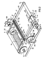
- FIG. 2 represents an embodiment of the shutter according to the invention in which the motor mechanism is a helical spring with non-contiguous turns 31, associated with a mechanism for supplying (extra) energy and sequencing ( trigger) and in which the curtain tensioning means are different from the elastic bands 27 of Figure 1.
- the angular setting device is similar to that of Figure 1 and operates in the same way, the pinion drive 21 of the roller 9 being symbolically shown opposite the pinion 14 because of the representation in exploded view of the angular setting device.
- the mainspring 31 is fixed at one of its ends to an anchoring casing 32 and at the other end to the driving pinion 7.
- the casing 32, secured to one end of the spring, is mounted by means of grooves 37 on a balancing piece of the spring 38, secured to the chassis.
- the rollers 6 and 9 and the pinions 12, 11 and 14 are supported by bearings mounted on the chassis, as in FIG. 1, as is the pinion 34 which has a non-return pawl 39.
- the rack 33 moves in translation on rollers not shown having a flat bottom groove for its guidance, being on one side in permanent contact with said rollers and meshed on the opposite side on the pinions 11 and 12.
- the shutter operates in the two directions indicated by the double arrow 41, with energy recovery, as explained below.
- the force exerted by the spring for a determined position of the assembly constituted by the curtains and the slit which separates them is adjusted by means of the balancing part of the spring, in particular so that, when the crankpin 35 is at a end of the slot 36, the rack 33 being substantially in its middle position, the motor spring is at rest.
- the spring 31, with non-contiguous turns can be loaded in both directions, that is to say in the direction of expansion of the turns (which is accompanied by a slight elongation) or in the direction of a contraction of the turns (accompanied by a slight shortening).
- the variation in length of the spring is made possible by means of the grooves 37.
- crank pin 35 being for example in its high position, the pinion 34 is rotated in the direction of the arrow 42 until the crank pin is located at the middle of slot 36.
- the spring is fully stretched, the rack is located at its extreme elongation on the right side, in the figure, and slot 5 is also completely to the right, outside the format of the apparatus.
- the pinion 7 which becomes motor under the action of the spring, a free wheel being provided for example for the pinion 34 in the direction of the arrow 42.
- the slot scans the view to be exposed and exceeds the format in the other direction given the inertia of all the moving parts which creates a partial tire of the spring in the opposite direction to the direction indicated above.
- This bandage of the spring is only partial because of the energy losses by friction.
- the return (oscillatory) of the mobile system to the rest position (spring not loaded) is made impossible by means of the non-return pawl 39.
- the electric motor which rotates the pinion 34 can be stopped during the rapid movement of the curtain . It can also operate continuously, its speed of rotation then determining the rate of shots, the successive views being scanned alternately in one direction then in the other by the exposure slit.
- the pinion 34 can be supported by a bearing secured to the chassis and the electric motor which is not coupled to it comprises a shaft provided with a cam which, at each half-turn of the pinion 34 presses against the control pin 35 until it passes its extreme position in the lateral direction.
- This variant is preferred because a dead time is respected between two successive movements of the curtain, during which the motor is not stressed by the shutter mechanism, which allows it to perform other tasks such as the transition from film to the next view in front of the exposure window.
- a device with symmetrical operation is thus obtained, such that most of the energy released by the spring is recovered by the spring itself and for which only a slight boost of energy provided by the electric motor is necessary to carry the spring at its maximum tension.
- the main advantages of this curtain drive mode are: obtaining a high speed for the curtains to run, of the order of a few meters per second, low energy consumption and for each shot, a substantially constant speed range when passing the slot over the device format.
- the tensioning means consist of two elastic belts 42 and 43 preferably round, which surround the rollers 6 and 9 in grooves provided for this purpose by closing on themselves and whose ends are fixed to the edges 3 and 4 of the slot 5 so as to pull the latter towards the other.
- these edges are materialized by metal parts 44 and 45 (profiles for example) in which the edges of the curtains are pinched and fixed (not visible in FIG. 2) .
- the metal parts 44 and 45 extend beyond the curtains on either side so as to constitute free ends in which the anchoring of the belts 42 and 43 is carried out which are preferably constituted by helical springs of small diameter.
- Each spring has at its end a cable or a string 46 which passes through one of the metal parts and which is fixed to the other metal part.
- the strings 46 extend as much as possible in the plane of the curtains 1 and 2. It will be noted that, in the embodiment of FIG. 2, the spacing between the drive rollers 6 and 9 is greater than in the embodiment of FIG. 1. This is due to the fact that the means of tensioning the curtains, in FIG. 2 , can not be wound around the rollers 6 and 9 unlike the case of Figure 1; However, after each shot, the exposure slit must be obscured or at the very least be clearly outside the format to avoid veiling the film. The remote arrangement of the rollers, in FIG. 2, guarantees the film against any entry of unwanted light through the exposure slot 5.
- FIG. 3 comprises the same motor mechanism and the same energy boosting and triggering mechanism as the embodiment of FIG. 2.
- the means of tensioning the curtains and the wedging device angular are different from those shown in Figures 1 and 2.
- the curtains are not juxtaposed but superimposed so that one can define a first curtain called upper 47 and a second curtain called lower 48, arranged parallel to 1 mm about a distance below the upper curtain in the figure.
- Each curtain is kept taut in its plane thanks to the fact that it is supported and driven by two rollers placed on either side of the format, which constitutes the tensioning means: the first curtain 47 is driven by the roller 6 and by a third roller 49 rotatably supported by the frame and itself driven in rotation from the second pinion 11 by means of a pinion 51 integral in rotation with the pinion 11, and the second curtain 48 is driven by the second roller 9 and by a fourth roller 52 supported in rotation by the chassis, close to the motor mechanism, and itself driven in rotation by a tensioning tape 53 which is wound around the second and fourth rollers supporting the second curtain 48 with directions of 'winding opposite to that of the curtain 48.
- the rollers 48 and 52 have, in operation, the same peripheral speed as the rollers 6 and 9.
- the first and second curtains each have an opening 57, resp ectively 58 in the form of rectangular windows of the same height, both of which can fully discover the format and one of whose short sides 55, 56 respectively constitutes an edge of the exposure slot.
- This arrangement means that each curtain is constituted by two half-curtains connected to one another by suspenders 54.
- the curtains 47 and 48 of FIG. 3 are preferably made of stainless steel or titanium , with a thickness of the order of 35 micrometers.
- the angular setting device referenced 59 in FIG. 3 can be the same as in FIGS. 1 and 2. However, the more elaborate embodiment of the curtains, their mode of drive and their tensioning means described above allows an embodiment more elaborate of the angular setting device which makes possible the photography in pose, by means of an appropriate adjustment.
- the first drum 60 supports, in addition to the pinion 11, the pinion 51 and has one (or more) ramp (s) 70.
- the second drum, referenced 61 is longer than the drum 60 and the ramp (s) 62 which it comprises for guiding the finger (s) 25 extends, backwards in the figure, along a generator of the cylinder 61.
- the part 24 is pushed to the bottom, by means of the rod 23, with pressure effect against the inner ring, integral with the frame and therefore immobile from the drum support bearing 61.
- the shutter can then operate to take pictures with an unlimited exposure time by means of the single upper curtain 47. This mode is similar to that of conventional commercial devices with a single shutter curtain.
- the motor is again actuated and the curtain 47 goes back over the format in the opposite direction, to return to its initial position coinciding with a second stop of the motor (see Figure 4d), until the next shot.
- the transition to the instantaneous shooting position takes place by traction on the axis 23 which again makes the drums 60 and 61 integral.
- the latter preferably have, at their open end, a flare 63 (FIG. 3).
- the rod 23 can pass through its center with smoothing the support bearing of the drum 61 and actuate, beyond this bearing, by means of a mechanism which is similar to the device 59, a potentiometer whose output voltage V is representative of the dimension d (respectively of the exposure time T).
- Figure 4 shows in a, b, c, d and e different possible operating phases for the embodiment of Figure 3, the operation illustrated by Figure 4a, 4b or 4c being also possible for the embodiments of the figures 1 and 2 with a single drive roller per curtain (6, respectively 9).
- the corresponding position of the control crankpin 35 in the slot 36 is shown on the right of the figures.
- the format of the device is indicated by the two phantom lines 65, the middle of the format being indicated by the phantom line 66. on either side of the format the curtain drive rollers, 6 and 49 on the one hand and 9 and 52 on the other.
- the anchoring line of the curtains on the rollers is symbolized by a point 67 against the circle which represents each roller and by means of a choice of origin for the anchoring of the curtains on the rollers, an otherwise arbitrary choice insofar as a winding sufficient minimum is respected around each roller, the number marked inside each circle indicates the number of turns made by the curtains around the rollers.
- an intermediate value di has been chosen for the slot width d.
- FIG. 4a represents the position of the shutter, motor spring 31 not loaded, the crank pin 35 being located at one of the ends of the slot 36.
- FIG. 4b represents, for the same slot width di, the system pulled towards the left under the action of the crankpin 35 which is in its extreme position to the left, ready for triggering.
- the shutter has operated, the exposure slit 5 scanning the format from left to right at a substantially constant high speed, the exposure slit is immobilized for a short time on the right outside the format during which the change of view was carried out and then resumed its movement to the right, under the action of the electric motor and the crankpin 35, until reaching the position represented by FIG. 4c.
- the next shot corresponds to the passage from position 4c to position 4b according to an operation in symmetrical opposite direction to the previous one.
- Figures 4d and 4e illustrate a exposure shot.
- the starting position in which the disengagement of the drum 61 takes place is indicated in FIG. 4e, this position also being the same as that in FIG. 4b.
- the passage from position 4d to position 4e takes place, for the upper curtain 47 as described above for the passage from 4b to 4c.
- the lower curtain 48 remains stationary so that, in the 4th position, the format is entirely uncovered.
- the electric motor is again actuated and the curtains 47 and 48 return to their position 4d (respectively 4b if the rod 23 has been pulled).
- FIG. 5 shows how the angular wedging device 59 of FIG. 3 can be produced.
- certain parts are represented as a single part whereas in practice they consist of several separate parts, which is necessary to allow mounting, the separate parts being secured after mounting by any known means. These include bearing support parts.
- the chassis is referenced 71 and the various parts referenced in FIG. 3 are identifiable, namely the second pinion 11, the third pinion 14, the drums 60 and 61 with their ramps 70 and 62 respectively, the rod 23, the part 24 supporting the finger (s) 25, the rack 33 and the pinion 51.
- the drum 60 is rotatably mounted on the chassis by means of a bearing 72, and on the opposite side, the drum 61 by means of a bearing 73.
- Drum 61 can rotate around the drum 60 thanks to at least three rollers 74 whose axes are supported by the drum 60.
- the part 24 rotates by means of a bearing 75, around a part 76 mounted tightly on the rod 23 and which is secured to a braking plate 77.
- One end 81 of the rod 23 is threaded and is screwed into a bolt 82 which is supported by the chassis by means of a plain bearing; this arrangement allows, by rotating the bolt 82, to advance or retract the rod 23 and therefore the assembly formed by the elements 24, 25, 75, 76, 77 inside the drums 60 and 61, provided that the rod-23 is immobilized in rotation.
- This immobilization in rotation is achieved by means of a finger 83 fixed perpendicularly to the other end of the rod 23 and engaged in a rectilinear slot 84 formed in the chassis.
- Bolt 82 can be operated by hand or from an electronically controlled electronic motor.
- a broken line rectangle 80 symbolizes the presence of other fingers 25 cooperating with other slots 70, 62 made in the drums 60 and 61.
- the fingers 25 comprise rotating rings 85 intended to facilitate their movement across the ramps.
- the drum 61 is no longer secured to the drum 60.
- a slight additional push puts the brake disc 77 in contact with the bottom 92 of the drum 61, this which immobilizes the latter since the disc 77 is itself stationary in rotation thanks to the finger 83.
- the braking disc could be integral with the part 24 and press against the face 93 of the chassis which extends substantially in the plane of the surface 92.
- the maximum insertion of the rod 23 acts mechanically on a mechanical or electromechanical control, the function of which is to inhibit a sequence of advancement of the film in two during a complete operating cycle of the mechanism. training, which avoids, when taking exposure shots, spoiling half of the photosensitive surface of the film to be impressed.
- This mechanism consists of a cylinder sector 86 provided with a curved ramp 87 and rotatably supported by the chassis by means of bearings 88.
- the finger 83 crosses the ramp 87 and the sector 86 is provided with a pinion 89 which is meshed on the axis 90 of a potentiometer 91.
- the translational movement of the finger 83 causes the rotation of the axis 90 according to a law defined by the curvature of the ramp 87.
- V being the output voltage of the potentiometer 91, it it is thus possible to establish the necessary transfer function between parameters d and V or T and V.
- the output signal from the potentiometer (voltage V) can be used on the one hand to indicate the value of the time of exposure to a visualized display and / or a recording, on the other hand as an output control servo for the illumination of the film operating in conjunction with a diaphragm control either at imposed exposure time or in time variable placement alone or simultaneously with the diaphragm.
Landscapes
- Physics & Mathematics (AREA)
- General Physics & Mathematics (AREA)
- Shutters For Cameras (AREA)
- Operating, Guiding And Securing Of Roll- Type Closing Members (AREA)
Applications Claiming Priority (2)
| Application Number | Priority Date | Filing Date | Title |
|---|---|---|---|
| FR8212138A FR2530041A1 (fr) | 1982-07-09 | 1982-07-09 | Obturateur photographique a rideaux |
| FR8212138 | 1982-07-09 |
Publications (2)
| Publication Number | Publication Date |
|---|---|
| EP0099154A1 EP0099154A1 (fr) | 1984-01-25 |
| EP0099154B1 true EP0099154B1 (fr) | 1987-01-28 |
Family
ID=9275875
Family Applications (1)
| Application Number | Title | Priority Date | Filing Date |
|---|---|---|---|
| EP83201008A Expired EP0099154B1 (fr) | 1982-07-09 | 1983-07-06 | Obturateur photographique à rideaux |
Country Status (5)
| Country | Link |
|---|---|
| US (1) | US4641938A (enExample) |
| EP (1) | EP0099154B1 (enExample) |
| JP (1) | JPS5923329A (enExample) |
| DE (1) | DE3369574D1 (enExample) |
| FR (1) | FR2530041A1 (enExample) |
Families Citing this family (4)
| Publication number | Priority date | Publication date | Assignee | Title |
|---|---|---|---|---|
| JPH0730679B2 (ja) * | 1993-04-26 | 1995-04-10 | 株式会社大林組 | 自穿孔ボルトの埋設方法 |
| DE502004010336D1 (de) * | 2003-07-14 | 2009-12-24 | Tecan Trading Ag | Schlitzblende in einem Monochromator |
| FR2978790B1 (fr) * | 2011-08-05 | 2013-08-30 | Somfy Sas | Procede de commande d'un ecran et actionneur adapte pour un tel procede |
| CN110426841A (zh) * | 2019-06-26 | 2019-11-08 | 哈尔滨新光光电科技股份有限公司 | 一种基于钢带运动的可变光阑调光装置 |
Family Cites Families (15)
| Publication number | Priority date | Publication date | Assignee | Title |
|---|---|---|---|---|
| FR376012A (fr) * | 1906-05-21 | 1907-07-29 | Optische Anstalt C. P. Goerz Aktiengesellschaft | Obturateur à rideau |
| US1492357A (en) * | 1921-01-29 | 1924-04-29 | Eastman Kodak Co | Photographic shutter |
| US2218248A (en) * | 1938-09-24 | 1940-10-15 | Eastman Kodak Co | Focal plane shutter construction |
| US2335690A (en) * | 1941-12-01 | 1943-11-30 | John F Morse | Variable aperture shutter |
| US2446638A (en) * | 1945-11-08 | 1948-08-10 | Eastman Kodak Co | Focal-plane curtain shutter for cameras |
| FR1169644A (fr) * | 1956-01-12 | 1958-12-31 | Optische Ind De Oude Delft Nv | Obturateur de plaque |
| US2907256A (en) * | 1956-01-13 | 1959-10-06 | Fairchild Camera Instr Co | Focal plane camera shutter |
| US3133486A (en) * | 1961-06-09 | 1964-05-19 | Chicago Aerial Ind Inc | Focal plane shutter mechanism |
| US3554106A (en) * | 1967-08-28 | 1971-01-12 | Hycon Mfg Co | Shutter device |
| US3577901A (en) * | 1968-08-02 | 1971-05-11 | Bourns Cai Inc | Remotely controlled focal plane shutter |
| SE348059B (enExample) * | 1970-05-06 | 1972-08-21 | Hasselblad | |
| US3739704A (en) * | 1970-11-09 | 1973-06-19 | Minolta Camera Kk | Focal plane shutter control mechanism for a photographic shutter |
| JPS5156621A (ja) * | 1974-11-14 | 1976-05-18 | Sugaya Kogaku Kenkyusho Jugen | Kamerayomakushatsutasochi |
| SE378312B (enExample) * | 1974-11-15 | 1975-08-25 | Hasselblad | |
| JPS5916913Y2 (ja) * | 1975-09-18 | 1984-05-17 | オリンパス光学工業株式会社 | 幕シヤツタ−のスタ−ト位置調整装置 |
-
1982
- 1982-07-09 FR FR8212138A patent/FR2530041A1/fr active Granted
-
1983
- 1983-07-06 DE DE8383201008T patent/DE3369574D1/de not_active Expired
- 1983-07-06 EP EP83201008A patent/EP0099154B1/fr not_active Expired
- 1983-07-09 JP JP58124107A patent/JPS5923329A/ja active Granted
-
1985
- 1985-09-16 US US06/776,092 patent/US4641938A/en not_active Expired - Fee Related
Also Published As
| Publication number | Publication date |
|---|---|
| JPH0450565B2 (enExample) | 1992-08-14 |
| EP0099154A1 (fr) | 1984-01-25 |
| FR2530041B1 (enExample) | 1984-11-23 |
| JPS5923329A (ja) | 1984-02-06 |
| DE3369574D1 (en) | 1987-03-05 |
| US4641938A (en) | 1987-02-10 |
| FR2530041A1 (fr) | 1984-01-13 |
Similar Documents
| Publication | Publication Date | Title |
|---|---|---|
| CH634896A5 (fr) | Dispositif de commande pour moto-reducteur electrique. | |
| FR2594993A1 (fr) | Dispositif pour la visualisation de messages publicitaires | |
| EP2735919B1 (fr) | Mouvement de montre comportant une fusée | |
| EP0099154A1 (fr) | Obturateur photographique à rideaux | |
| FR2651335A1 (fr) | Appareil photographique motorise. | |
| FR2500178A1 (fr) | Dispositif enrouleur pour chargement automatique de film d'un appareil photographique | |
| CH707271A2 (fr) | Mouvement de montre comportant une fusée. | |
| CH519742A (fr) | Mécanisme de minuterie pour pièce d'horlogerie | |
| EP0468890B1 (fr) | Dispositif d'obturation d'un faisceau devant frapper par intermittence un point déterminé | |
| FR2478833A1 (fr) | Appareil de prise de vues automatique de surveillance reglable | |
| FR3087474A1 (fr) | Procede de controle d'un systeme d'actionnement d'un premier et d'un second ecrans et systeme d'actionnement | |
| WO1994010603A1 (fr) | Boitier d'appareil photographique | |
| EP0021529A1 (fr) | Appareil cinématographique de prises de vues ou de projection comportant un dispositif d'antibourrage de film | |
| BE514432A (enExample) | ||
| BE514463A (enExample) | ||
| CH163293A (fr) | Dispositif enrouleur-dérouleur d'une bande sans fin enroulée, à l'exception d'une boucle, en couches superposées formant une spirale. | |
| FR2706878A1 (en) | Stop and rapid-return device for a tie rolling-up machine | |
| FR2462735A1 (fr) | Camera de prise de vue | |
| BE414594A (enExample) | ||
| FR2489005A1 (fr) | Dispositif d'entrainement, de traction, d'obturation et de reglage de film pour appareil programmable | |
| BE416608A (enExample) | ||
| BE551528A (enExample) | ||
| CH289394A (fr) | Appareil photographique stéréoscopique. | |
| CH171771A (fr) | Appareil de projection permettant de faire varier en grandeur la projection de chaque image. | |
| CH453883A (fr) | Caméra cinématographique |
Legal Events
| Date | Code | Title | Description |
|---|---|---|---|
| PUAI | Public reference made under article 153(3) epc to a published international application that has entered the european phase |
Free format text: ORIGINAL CODE: 0009012 |
|
| AK | Designated contracting states |
Designated state(s): CH DE FR GB LI SE |
|
| 17P | Request for examination filed |
Effective date: 19840308 |
|
| GRAA | (expected) grant |
Free format text: ORIGINAL CODE: 0009210 |
|
| AK | Designated contracting states |
Kind code of ref document: B1 Designated state(s): CH DE FR GB LI SE |
|
| REF | Corresponds to: |
Ref document number: 3369574 Country of ref document: DE Date of ref document: 19870305 |
|
| PLBE | No opposition filed within time limit |
Free format text: ORIGINAL CODE: 0009261 |
|
| STAA | Information on the status of an ep patent application or granted ep patent |
Free format text: STATUS: NO OPPOSITION FILED WITHIN TIME LIMIT |
|
| 26N | No opposition filed | ||
| REG | Reference to a national code |
Ref country code: FR Ref legal event code: TP |
|
| REG | Reference to a national code |
Ref country code: CH Ref legal event code: PUE Owner name: THOMSON-TRT DEFENSE |
|
| PGFP | Annual fee paid to national office [announced via postgrant information from national office to epo] |
Ref country code: CH Payment date: 19940613 Year of fee payment: 12 |
|
| PGFP | Annual fee paid to national office [announced via postgrant information from national office to epo] |
Ref country code: SE Payment date: 19940620 Year of fee payment: 12 Ref country code: DE Payment date: 19940620 Year of fee payment: 12 |
|
| PGFP | Annual fee paid to national office [announced via postgrant information from national office to epo] |
Ref country code: GB Payment date: 19940621 Year of fee payment: 12 |
|
| PGFP | Annual fee paid to national office [announced via postgrant information from national office to epo] |
Ref country code: FR Payment date: 19940722 Year of fee payment: 12 |
|
| EAL | Se: european patent in force in sweden |
Ref document number: 83201008.6 |
|
| PG25 | Lapsed in a contracting state [announced via postgrant information from national office to epo] |
Ref country code: GB Effective date: 19950706 |
|
| PG25 | Lapsed in a contracting state [announced via postgrant information from national office to epo] |
Ref country code: SE Effective date: 19950707 |
|
| PG25 | Lapsed in a contracting state [announced via postgrant information from national office to epo] |
Ref country code: LI Effective date: 19950731 Ref country code: CH Effective date: 19950731 |
|
| GBPC | Gb: european patent ceased through non-payment of renewal fee |
Effective date: 19950706 |
|
| REG | Reference to a national code |
Ref country code: CH Ref legal event code: PL |
|
| PG25 | Lapsed in a contracting state [announced via postgrant information from national office to epo] |
Ref country code: DE Effective date: 19960402 |
|
| EUG | Se: european patent has lapsed |
Ref document number: 83201008.6 |
|
| PG25 | Lapsed in a contracting state [announced via postgrant information from national office to epo] |
Ref country code: FR Effective date: 19960430 |
|
| REG | Reference to a national code |
Ref country code: FR Ref legal event code: ST |
|
| REG | Reference to a national code |
Ref country code: FR Ref legal event code: ST |
|
| REG | Reference to a national code |
Ref country code: FR Ref legal event code: ST |