EP0098062B1 - Vehicle lamp assemblies - Google Patents
Vehicle lamp assemblies Download PDFInfo
- Publication number
- EP0098062B1 EP0098062B1 EP83303298A EP83303298A EP0098062B1 EP 0098062 B1 EP0098062 B1 EP 0098062B1 EP 83303298 A EP83303298 A EP 83303298A EP 83303298 A EP83303298 A EP 83303298A EP 0098062 B1 EP0098062 B1 EP 0098062B1
- Authority
- EP
- European Patent Office
- Prior art keywords
- light source
- lamp assembly
- common axis
- assembly according
- light
- Prior art date
- Legal status (The legal status is an assumption and is not a legal conclusion. Google has not performed a legal analysis and makes no representation as to the accuracy of the status listed.)
- Expired
Links
- 230000000712 assembly Effects 0.000 title description 2
- 238000000429 assembly Methods 0.000 title description 2
- 230000015572 biosynthetic process Effects 0.000 claims description 9
- 238000005755 formation reaction Methods 0.000 claims description 9
- 230000003287 optical effect Effects 0.000 description 4
- 230000011664 signaling Effects 0.000 description 2
- 229920003023 plastic Polymers 0.000 description 1
Images

Classifications
-
- F—MECHANICAL ENGINEERING; LIGHTING; HEATING; WEAPONS; BLASTING
- F21—LIGHTING
- F21S—NON-PORTABLE LIGHTING DEVICES; SYSTEMS THEREOF; VEHICLE LIGHTING DEVICES SPECIALLY ADAPTED FOR VEHICLE EXTERIORS
- F21S43/00—Signalling devices specially adapted for vehicle exteriors, e.g. brake lamps, direction indicator lights or reversing lights
- F21S43/20—Signalling devices specially adapted for vehicle exteriors, e.g. brake lamps, direction indicator lights or reversing lights characterised by refractors, transparent cover plates, light guides or filters
- F21S43/26—Refractors, transparent cover plates, light guides or filters not provided in groups F21S43/235 - F21S43/255
-
- F—MECHANICAL ENGINEERING; LIGHTING; HEATING; WEAPONS; BLASTING
- F21—LIGHTING
- F21S—NON-PORTABLE LIGHTING DEVICES; SYSTEMS THEREOF; VEHICLE LIGHTING DEVICES SPECIALLY ADAPTED FOR VEHICLE EXTERIORS
- F21S43/00—Signalling devices specially adapted for vehicle exteriors, e.g. brake lamps, direction indicator lights or reversing lights
- F21S43/20—Signalling devices specially adapted for vehicle exteriors, e.g. brake lamps, direction indicator lights or reversing lights characterised by refractors, transparent cover plates, light guides or filters
- F21S43/255—Filters
-
- F—MECHANICAL ENGINEERING; LIGHTING; HEATING; WEAPONS; BLASTING
- F21—LIGHTING
- F21S—NON-PORTABLE LIGHTING DEVICES; SYSTEMS THEREOF; VEHICLE LIGHTING DEVICES SPECIALLY ADAPTED FOR VEHICLE EXTERIORS
- F21S43/00—Signalling devices specially adapted for vehicle exteriors, e.g. brake lamps, direction indicator lights or reversing lights
- F21S43/40—Signalling devices specially adapted for vehicle exteriors, e.g. brake lamps, direction indicator lights or reversing lights characterised by the combination of reflectors and refractors
-
- F—MECHANICAL ENGINEERING; LIGHTING; HEATING; WEAPONS; BLASTING
- F21—LIGHTING
- F21V—FUNCTIONAL FEATURES OR DETAILS OF LIGHTING DEVICES OR SYSTEMS THEREOF; STRUCTURAL COMBINATIONS OF LIGHTING DEVICES WITH OTHER ARTICLES, NOT OTHERWISE PROVIDED FOR
- F21V5/00—Refractors for light sources
- F21V5/008—Combination of two or more successive refractors along an optical axis
-
- F—MECHANICAL ENGINEERING; LIGHTING; HEATING; WEAPONS; BLASTING
- F21—LIGHTING
- F21V—FUNCTIONAL FEATURES OR DETAILS OF LIGHTING DEVICES OR SYSTEMS THEREOF; STRUCTURAL COMBINATIONS OF LIGHTING DEVICES WITH OTHER ARTICLES, NOT OTHERWISE PROVIDED FOR
- F21V5/00—Refractors for light sources
- F21V5/04—Refractors for light sources of lens shape
- F21V5/045—Refractors for light sources of lens shape the lens having discontinuous faces, e.g. Fresnel lenses
-
- F—MECHANICAL ENGINEERING; LIGHTING; HEATING; WEAPONS; BLASTING
- F21—LIGHTING
- F21V—FUNCTIONAL FEATURES OR DETAILS OF LIGHTING DEVICES OR SYSTEMS THEREOF; STRUCTURAL COMBINATIONS OF LIGHTING DEVICES WITH OTHER ARTICLES, NOT OTHERWISE PROVIDED FOR
- F21V7/00—Reflectors for light sources
- F21V7/04—Optical design
- F21V7/08—Optical design with elliptical curvature
Definitions
- This invention relates to vehicle lamp assemblies and more particularly to signalling lights in which the outer cover or lens element extends round the corner of the vehicle.
- the invention is also applicable to signalling lights in which the outer cover or lens element is significantly larger in one of two mutually perpendicular directions than in the other.
- GB-A-812148 discloses a vehicle lamp assembly with-a substantially plane intermediate lens having circular Fresnel prism formations on its inner surface and refracting prisms on its outer surface. This type of assembly can only be used when there is room for a plane lens between the lamp and the outer cover.
- the present invention aims to provide a collector which, while not being of rotationally symmetrical form, produces a collimated beam without requiring a multiplicity of individually designed prism elements.
- a vehicle lamp assembly comprises a light source, a light transmitting cover element and a light transmitting intermediate element disposed between the source and the cover element and comprising coaxial part-cylindrical inner and outer surfaces located with the light source on their common axis, one of said part-cylindrical surfaces carrying elongated Fresnel prism formations of uniform cross-section extending in respective planes extending parallel to the common axis and the other part-cylindrical surface carrying elongated Fresnel prism formations of uniform cross-section extending in respective planes perpendicular to said common axis.
- the prism formations on the outer surface are parallel to the common axis while those on the inner surface are perpendicular thereto.
- the cover element may carry conventional pillow optics on one of its surfaces, preferably the inner surface.
- the light source comprises a primary light source such as an electric filament lamp.
- the light source comprises a zone on to which light is focused from a remote primary source.
- the light source of the invention may be one focus of an ellipse with the primary light source at the other focus.
- the front direction indicator lamp of a motor car consists of a housing 10 covered by a lens 12 with conventional pillow optics on its inner surface.
- the housing 10 includes a bulb holder 14 which supports a bulb 16.
- a cylindrical intermediate element 18 of transparent plastic Located between the bulb 16 and the lens 12 is a cylindrical intermediate element 18 of transparent plastic, the axis of the cylinder passing through the filament of the bulb 16.
- the inner surface of the intermediate element 18, i.e. the surface closer to the lamp 16, carries elongated Fresnel prism formations extending in respective planes perpendicular to the axis of the cylinder, while the outer surface carries Fresnel prism formations extending parallel to such axis.
- rays of light therefrom such as the ray 24 are deflected into horizontal planes parallel to the optical axis of the lamp, as can best be seen in Figure 1, but they still extend radially within such planes, as can be seen in Figure 2. They are deflected parallel to the optical axis of the lamp within such planes, i.e. in the vertical direction, by the Fresnel prisms on the outer surface, as shown in Figure 2.
- a parallel beam is directed on to the entire inner surface of the outer lens 12 where it is given the required amount of divergence by the pillow optics.
- the invention may also be applied to a so-called "contrast" light of the type described in GB-A-1016301.
- the housing 30 of the lamp illustrated in Figures 3 and 4 has an outer lens 12 and an intermediate element 18 which are identical with the correspondingly numbered components illustrated in Figures 1 and 2 and which will therefore not be described in detail.
- a light transmitting element 38 coloured in accordance with the required colour of the lamp when illuminated, is mounted at the first-mentioned focus 32 in an opaque support 40.
- the outer surface of the support 40 is coloured is accordance with the required colour of the lamp when not illuminated, usually white for a front direction indicator.
Description
- This invention relates to vehicle lamp assemblies and more particularly to signalling lights in which the outer cover or lens element extends round the corner of the vehicle. The invention is also applicable to signalling lights in which the outer cover or lens element is significantly larger in one of two mutually perpendicular directions than in the other.
- Conventional optical collimating systems are essentially rotationally symmetrical about their optical axis. This can produce conflicting design requirements in a lamp where the physical shape of the outer lens and housing, through asymmetry or otherwise, are not compatible with the interposition of a rotationally symmetrical screen. GB-A-812148 discloses a vehicle lamp assembly with-a substantially plane intermediate lens having circular Fresnel prism formations on its inner surface and refracting prisms on its outer surface. This type of assembly can only be used when there is room for a plane lens between the lamp and the outer cover.
- One solution of this problem is to use a Fresnel collector constructed in a rotationally asymmetrical form. However, such a collector would generally require a large number of prisms, each individually designed. The present invention aims to provide a collector which, while not being of rotationally symmetrical form, produces a collimated beam without requiring a multiplicity of individually designed prism elements.
- According to the invention, a vehicle lamp assembly comprises a light source, a light transmitting cover element and a light transmitting intermediate element disposed between the source and the cover element and comprising coaxial part-cylindrical inner and outer surfaces located with the light source on their common axis, one of said part-cylindrical surfaces carrying elongated Fresnel prism formations of uniform cross-section extending in respective planes extending parallel to the common axis and the other part-cylindrical surface carrying elongated Fresnel prism formations of uniform cross-section extending in respective planes perpendicular to said common axis.
- Preferably the prism formations on the outer surface are parallel to the common axis while those on the inner surface are perpendicular thereto.
- The cover element may carry conventional pillow optics on one of its surfaces, preferably the inner surface.
- In one form of the invention, the light source comprises a primary light source such as an electric filament lamp. In another form of the invention, the light source comprises a zone on to which light is focused from a remote primary source. For example the light source of the invention may be one focus of an ellipse with the primary light source at the other focus.
- Two embodiments of the invention will now be described, by way of example, with reference to the accompanying drawings in which:
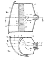
- Figure 1 is a vertical cross-sectional view of the first embodiment of the invention, taken on the line 1-1 in Figure 2;
- Figure 2 is a cross-sectional view taken on the line 2-2 in Figure 1;
- Figure 3 is a vertical cross-sectional view of another embodiment of the invention, taken on the line 3-3 in Figure 4; and
- Figure 4 is a cross-sectional view taken on the line 4-4 in Figure 3.
- Referring to Figures 1 and 2, the front direction indicator lamp of a motor car consists of a
housing 10 covered by alens 12 with conventional pillow optics on its inner surface. Thehousing 10 includes abulb holder 14 which supports abulb 16. - Located between the
bulb 16 and thelens 12 is a cylindricalintermediate element 18 of transparent plastic, the axis of the cylinder passing through the filament of thebulb 16. The inner surface of theintermediate element 18, i.e. the surface closer to thelamp 16, carries elongated Fresnel prism formations extending in respective planes perpendicular to the axis of the cylinder, while the outer surface carries Fresnel prism formations extending parallel to such axis. - When the
bulb 16 is illuminated, rays of light therefrom, such as theray 24 are deflected into horizontal planes parallel to the optical axis of the lamp, as can best be seen in Figure 1, but they still extend radially within such planes, as can be seen in Figure 2. They are deflected parallel to the optical axis of the lamp within such planes, i.e. in the vertical direction, by the Fresnel prisms on the outer surface, as shown in Figure 2. Thus a parallel beam is directed on to the entire inner surface of theouter lens 12 where it is given the required amount of divergence by the pillow optics. - Referring to Figures 3 and 4, the invention may also be applied to a so-called "contrast" light of the type described in GB-A-1016301. The
housing 30 of the lamp illustrated in Figures 3 and 4 has anouter lens 12 and anintermediate element 18 which are identical with the correspondingly numbered components illustrated in Figures 1 and 2 and which will therefore not be described in detail. - Located on the axis on the cylindrical
intermediate element 18 is onefocus 32 of anellipsoidal reflector 34 which has the filament of abulb 36 at its other focus. Alight transmitting element 38, coloured in accordance with the required colour of the lamp when illuminated, is mounted at the first-mentionedfocus 32 in anopaque support 40. The outer surface of thesupport 40 is coloured is accordance with the required colour of the lamp when not illuminated, usually white for a front direction indicator.
Claims (5)
Applications Claiming Priority (2)
| Application Number | Priority Date | Filing Date | Title |
|---|---|---|---|
| GB8218271 | 1982-06-24 | ||
| GB8218271 | 1982-06-24 |
Publications (2)
| Publication Number | Publication Date |
|---|---|
| EP0098062A1 EP0098062A1 (en) | 1984-01-11 |
| EP0098062B1 true EP0098062B1 (en) | 1986-04-09 |
Family
ID=10531240
Family Applications (1)
| Application Number | Title | Priority Date | Filing Date |
|---|---|---|---|
| EP83303298A Expired EP0098062B1 (en) | 1982-06-24 | 1983-06-08 | Vehicle lamp assemblies |
Country Status (6)
| Country | Link |
|---|---|
| US (1) | US4577260A (en) |
| EP (1) | EP0098062B1 (en) |
| JP (1) | JPS599801A (en) |
| KR (1) | KR920001216B1 (en) |
| DE (1) | DE3362901D1 (en) |
| ES (1) | ES272989Y (en) |
Families Citing this family (44)
| Publication number | Priority date | Publication date | Assignee | Title |
|---|---|---|---|---|
| US4764871A (en) * | 1983-12-16 | 1988-08-16 | Robert Bosch Gmbh | Method for converting a rotational speed transducer output signal into a low-distortion signal |
| US4652979A (en) * | 1984-11-21 | 1987-03-24 | Koito Seisakusho Co., Ltd. | Lamp assembly for emitting a beam of light at an angle to its optical axis |
| DE3519271C1 (en) * | 1985-05-30 | 1986-08-28 | Westfälische Metall Industrie KG Hueck & Co, 4780 Lippstadt | Dimmed vehicle headlights based on the projection principle |
| US4859043A (en) * | 1987-05-07 | 1989-08-22 | Cibie Projecteurs | High efficiency signal light, in particular for a motor vehicle |
| US4972302A (en) * | 1988-07-18 | 1990-11-20 | Stanley Electric Co., Ltd. | Vehicle lamp having inner lens and reflector |
| JPH071687Y2 (en) * | 1988-08-22 | 1995-01-18 | 株式会社小糸製作所 | Lens for vehicle lighting |
| GB8824206D0 (en) * | 1988-10-15 | 1988-11-23 | Carello Lighting Plc | Motor vehicle headlamp |
| US5287101A (en) * | 1990-03-15 | 1994-02-15 | Koito Manufacturing Co., Ltd. | Vehicular turn signal lamp |
| US5040103A (en) * | 1990-03-19 | 1991-08-13 | Whelen Technologies, Inc. | Light assembly for wide area illumination |
| CH681478A5 (en) * | 1990-11-12 | 1993-03-31 | Ver Drahtwerke Ag | |
| US5249109A (en) * | 1991-08-09 | 1993-09-28 | Intermatic Incorporated | Outdoor variable focus light fixture |
| US5363009A (en) * | 1992-08-10 | 1994-11-08 | Mark Monto | Incandescent light with parallel grooves encompassing a bulbous portion |
| US5742438A (en) * | 1994-09-16 | 1998-04-21 | In Focus Systems, Inc. | Projection illumination system |
| JP3172659B2 (en) * | 1995-07-31 | 2001-06-04 | 株式会社小糸製作所 | Vehicle lighting |
| US5779341A (en) * | 1996-03-01 | 1998-07-14 | Ford Global Technologies, Inc. | Reduced package depth low-profile lamp with smoothly shaped lenses |
| US5791759A (en) * | 1996-03-01 | 1998-08-11 | Ford Global Technologies, Inc. | Reduced package depth low profile lamp with conic section cylinders |
| DE19647357A1 (en) * | 1996-11-15 | 1998-05-20 | Hella Kg Hueck & Co | Vehicle light |
| US5890796A (en) * | 1997-01-16 | 1999-04-06 | Ford Global Technologies, Inc. | Laser illuminated lighting system utilizing a diffractive optical element |
| JP3155935B2 (en) * | 1997-05-21 | 2001-04-16 | 株式会社小糸製作所 | Vehicle lighting |
| DE19732742A1 (en) * | 1997-07-30 | 1999-02-04 | Bosch Gmbh Robert | Direction indicator lamp for vehicles |
| US6036340A (en) * | 1998-03-03 | 2000-03-14 | Ford Global Technologies, Inc. | Dimpled manifold optical element for a vehicle lighting system |
| JP2003123519A (en) * | 2001-10-15 | 2003-04-25 | Honda Motor Co Ltd | Projector type head lamp |
| US20040202003A1 (en) * | 2003-04-11 | 2004-10-14 | Guide Corporation | Selective output wave-guide |
| US7452115B2 (en) | 2003-07-29 | 2008-11-18 | Turhan Alcelik | Headlamp with a continuous long-distance illumination without glaring effects |
| US20060007692A1 (en) * | 2004-07-07 | 2006-01-12 | Hsien Chen S | Lamp assembly |
| US7465075B2 (en) * | 2005-03-21 | 2008-12-16 | Visteon Global Technologies, Inc. | Lens assembly for an automobile light assembly having LED light source |
| DE102005022979B4 (en) * | 2005-05-19 | 2008-11-27 | Hella Kgaa Hueck & Co. | Signal light of a motor vehicle |
| FR2889731B1 (en) * | 2005-08-11 | 2008-03-07 | Thorn Europhane Sa | LIGHTING DEVICE WITH VARIABLE OPENING OF THE LIGHT BEAM |
| US7401948B2 (en) * | 2005-10-17 | 2008-07-22 | Visteon Global Technologies, Inc. | Near field lens having reduced size |
| US7489453B2 (en) * | 2005-11-15 | 2009-02-10 | Visteon Global Technologies, Inc. | Side emitting near field lens |
| US7160010B1 (en) | 2005-11-15 | 2007-01-09 | Visteon Global Technologies, Inc. | Light manifold for automotive light module |
| US7564070B2 (en) * | 2005-11-23 | 2009-07-21 | Visteon Global Technologies, Inc. | Light emitting diode device having a shield and/or filter |
| US7438454B2 (en) * | 2005-11-29 | 2008-10-21 | Visteon Global Technologies, Inc. | Light assembly for automotive lighting applications |
| JP4597890B2 (en) * | 2006-03-29 | 2010-12-15 | 株式会社小糸製作所 | Vehicle headlamp lamp unit |
| US7554742B2 (en) * | 2007-04-17 | 2009-06-30 | Visteon Global Technologies, Inc. | Lens assembly |
| US7967477B2 (en) * | 2007-09-06 | 2011-06-28 | Philips Lumileds Lighting Company Llc | Compact optical system and lenses for producing uniform collimated light |
| CN101886765A (en) * | 2010-07-26 | 2010-11-17 | 鸿富锦精密工业(深圳)有限公司 | LED area light source device |
| US8702288B2 (en) * | 2011-12-06 | 2014-04-22 | Ford Global Technologies, Llc | Optical element for a vehicle lighting assembly |
| US9677737B1 (en) * | 2013-04-15 | 2017-06-13 | Cooper Technologies Company | Dual lens structure for light fixtures |
| CN103994386A (en) * | 2014-05-29 | 2014-08-20 | 江苏迅驰汽车部件有限公司 | Automobile tail lamp |
| FR3025289B1 (en) * | 2014-09-03 | 2019-07-26 | Zodiac Aero Electric | LIGHTING AND / OR EXTERNAL SIGNALING PROJECTOR AND CORRESPONDING LIGHTING AND / OR SIGNALING SYSTEM |
| FR3047795B1 (en) * | 2016-02-16 | 2020-03-06 | Valeo Vision Belgique | SIGNALING LIGHT WITH FOCUSING BEAM WITHDRAWAL FROM THE OUTER SURFACE OF THE FIRE |
| JP6741467B2 (en) * | 2016-05-12 | 2020-08-19 | 株式会社小糸製作所 | Vehicle lighting |
| JP6885718B2 (en) * | 2016-12-27 | 2021-06-16 | 株式会社小糸製作所 | Vehicle combination lamps |
Family Cites Families (25)
| Publication number | Priority date | Publication date | Assignee | Title |
|---|---|---|---|---|
| US1345073A (en) * | 1915-06-11 | 1920-06-29 | Emerson L Clark | Headlight |
| US1399749A (en) * | 1919-05-05 | 1921-12-13 | Oliver E Conklin | Headlight-lens |
| US1883360A (en) * | 1929-01-29 | 1932-10-18 | American Safety Headlight Corp | Headlight |
| US1904574A (en) * | 1931-05-29 | 1933-04-18 | Simon W H Turner | Automobile headlight |
| US1995012A (en) * | 1932-05-13 | 1935-03-19 | Rivier Louis | Lighting device |
| US2044224A (en) * | 1934-07-14 | 1936-06-16 | Jr Gustave Adolphus Peple | Head lamp |
| US2119370A (en) * | 1937-02-17 | 1938-05-31 | Ladden Corp Van | Light control means for headlights and the like |
| GB812148A (en) * | 1954-09-27 | 1959-04-22 | Gen Motors Corp | Improvements in vehicle rear lamp assemblies |
| DE1183873B (en) * | 1962-05-26 | 1964-12-23 | Sendlinger Optische Glaswerke | Headlights for color signals, especially for traffic control |
| US3253255A (en) * | 1962-07-24 | 1966-05-24 | Elastic Stop Nut Corp | Signal lamp and focusing reflector |
| DE1186004B (en) * | 1963-08-21 | 1965-01-28 | Westfaelische Metall Ind K G H | Lamp emitting colored light, especially signal lamp for motor vehicles |
| US3969621A (en) * | 1974-11-18 | 1976-07-13 | Ford Motor Company | Motor vehicle light assembly utilizing total internal reflection |
| JPS52166382U (en) * | 1976-06-10 | 1977-12-16 | ||
| FR2378234A1 (en) * | 1977-01-24 | 1978-08-18 | Cibie Projecteurs | SIGNALING LIGHT WITH BUILT-IN REFLECTOR FOR VEHICLE |
| JPS53105566U (en) * | 1977-01-31 | 1978-08-24 | ||
| DE7710606U1 (en) * | 1977-04-02 | 1977-07-14 | Westfaelische Metall Industrie Kg, Hueck & Co, 4780 Lippstadt | SIGNAL LAMP FOR MOTOR VEHICLES |
| US4158222A (en) * | 1977-09-26 | 1979-06-12 | Gulf & Western Industries, Inc. | Limited visibility signal device |
| JPS5751146Y2 (en) * | 1978-09-21 | 1982-11-08 | ||
| US4293892A (en) * | 1979-12-18 | 1981-10-06 | Polaroid Corporation | Zoom light apparatus |
| FR2476798A1 (en) * | 1980-02-25 | 1981-08-28 | Cibie Projecteurs | FIRE, IN PARTICULAR FOR THE SIGNALING OF MOTOR VEHICLES |
| DE3020097C2 (en) * | 1980-05-27 | 1983-02-10 | Auer-Sog Glaswerke Gmbh, 3353 Bad Gandersheim | Signal light |
| FR2501333A1 (en) * | 1981-03-09 | 1982-09-10 | Cibie Projecteurs | Automotive signal lamp preventing phantom signals - uses shielded lamp with shaped screen immediately ahead to divert all light onto main reflector and to trap incident light |
| FR2507741B1 (en) * | 1981-06-11 | 1987-03-20 | Cibie Projecteurs | IMPROVEMENTS IN LIGHT FLOW RECOVERY SYSTEMS, PARTICULARLY FOR AUTOMOTIVE LIGHTING AND SIGNALING |
| FR2509429B1 (en) * | 1981-07-09 | 1986-05-16 | Cibie Projecteurs | COLORLESS APPEARANCE LIGHT FOR A MOTOR VEHICLE |
| IT1144616B (en) * | 1981-07-31 | 1986-10-29 | Fiat Auto Spa | FRONT LIGHT DIRECTION INDICATOR FOR MOTOR VEHICLES |
-
1983
- 1983-06-08 DE DE8383303298T patent/DE3362901D1/en not_active Expired
- 1983-06-08 EP EP83303298A patent/EP0098062B1/en not_active Expired
- 1983-06-16 ES ES1983272989U patent/ES272989Y/en not_active Expired
- 1983-06-18 KR KR1019830002728A patent/KR920001216B1/en not_active IP Right Cessation
- 1983-06-20 JP JP58110762A patent/JPS599801A/en active Granted
-
1984
- 1984-10-12 US US06/660,252 patent/US4577260A/en not_active Expired - Fee Related
Also Published As
| Publication number | Publication date |
|---|---|
| KR920001216B1 (en) | 1992-02-06 |
| EP0098062A1 (en) | 1984-01-11 |
| KR840005195A (en) | 1984-11-05 |
| US4577260A (en) | 1986-03-18 |
| ES272989U (en) | 1983-11-01 |
| DE3362901D1 (en) | 1986-05-15 |
| JPS645401B2 (en) | 1989-01-30 |
| JPS599801A (en) | 1984-01-19 |
| ES272989Y (en) | 1984-05-01 |
Similar Documents
| Publication | Publication Date | Title |
|---|---|---|
| EP0098062B1 (en) | Vehicle lamp assemblies | |
| SU1276266A3 (en) | Lamp unit | |
| US5592578A (en) | Peripheral optical element for redirecting light from an LED | |
| EP0132060B1 (en) | Vehicle lamp assembly | |
| US5762414A (en) | Indicating light, in particular a complementary stop light for a motor vehicle, having a number of light sources in line with each other | |
| KR19990083118A (en) | Lamp | |
| US4731713A (en) | Fog lamp | |
| EP0138588A1 (en) | Indiscernible lamp | |
| US4669034A (en) | Non-glare device for large surface light emitting means | |
| EP0649125B1 (en) | Device for preventing pseudo lighting phenomenon of signal lamp | |
| EP0128035B1 (en) | Vehicle lamp assembly | |
| EP0176582B1 (en) | Motor vehicle lamp, and a light unit for motor vehicles incorporating such lamps | |
| EP0097449B1 (en) | Vehicle lamp assembly | |
| GB2054120A (en) | Traffic light | |
| EP0509679A2 (en) | Vehicle Lamp | |
| US3317772A (en) | Headlight arrangement for automotive vehicles including a reflector and a light shield means | |
| US5924792A (en) | Modular dual port central lighting system | |
| EP0193294A2 (en) | Vehicle lamp assembly | |
| ES249300U (en) | Rear fog lamp for motor vehicles | |
| ES264017U (en) | Indicator lamp for automobile vehicle | |
| EP0104798A1 (en) | Lamp unit | |
| ES290544U (en) | Projector of laminar beam particularly for vehicles automoviles (Machine-translation by Google Translate, not legally binding) | |
| GB2077413A (en) | Vehicle lamp unit | |
| CN114370622A (en) | Compact projection type LED car lamp | |
| JPS581901A (en) | Lamp apparatus for vehicle |
Legal Events
| Date | Code | Title | Description |
|---|---|---|---|
| PUAI | Public reference made under article 153(3) epc to a published international application that has entered the european phase |
Free format text: ORIGINAL CODE: 0009012 |
|
| AK | Designated contracting states |
Designated state(s): DE FR GB IT |
|
| 17P | Request for examination filed |
Effective date: 19840530 |
|
| GRAA | (expected) grant |
Free format text: ORIGINAL CODE: 0009210 |
|
| AK | Designated contracting states |
Kind code of ref document: B1 Designated state(s): DE FR GB IT |
|
| REF | Corresponds to: |
Ref document number: 3362901 Country of ref document: DE Date of ref document: 19860515 |
|
| ET | Fr: translation filed | ||
| ITF | It: translation for a ep patent filed |
Owner name: ING. A. GIAMBROCONO & C. S.R.L. |
|
| PLBE | No opposition filed within time limit |
Free format text: ORIGINAL CODE: 0009261 |
|
| STAA | Information on the status of an ep patent application or granted ep patent |
Free format text: STATUS: NO OPPOSITION FILED WITHIN TIME LIMIT |
|
| 26N | No opposition filed | ||
| ITTA | It: last paid annual fee | ||
| PGFP | Annual fee paid to national office [announced via postgrant information from national office to epo] |
Ref country code: GB Payment date: 19920505 Year of fee payment: 10 |
|
| PGFP | Annual fee paid to national office [announced via postgrant information from national office to epo] |
Ref country code: FR Payment date: 19920609 Year of fee payment: 10 |
|
| PGFP | Annual fee paid to national office [announced via postgrant information from national office to epo] |
Ref country code: DE Payment date: 19920702 Year of fee payment: 10 |
|
| PG25 | Lapsed in a contracting state [announced via postgrant information from national office to epo] |
Ref country code: GB Effective date: 19930608 |
|
| GBPC | Gb: european patent ceased through non-payment of renewal fee |
Effective date: 19930608 |
|
| PG25 | Lapsed in a contracting state [announced via postgrant information from national office to epo] |
Ref country code: FR Effective date: 19940228 |
|
| PG25 | Lapsed in a contracting state [announced via postgrant information from national office to epo] |
Ref country code: DE Effective date: 19940301 |
|
| REG | Reference to a national code |
Ref country code: FR Ref legal event code: ST |