EP0097331A2 - Device for exchanging forme cylinders in rotary intaglio printing presses - Google Patents
Device for exchanging forme cylinders in rotary intaglio printing presses Download PDFInfo
- Publication number
- EP0097331A2 EP0097331A2 EP83105886A EP83105886A EP0097331A2 EP 0097331 A2 EP0097331 A2 EP 0097331A2 EP 83105886 A EP83105886 A EP 83105886A EP 83105886 A EP83105886 A EP 83105886A EP 0097331 A2 EP0097331 A2 EP 0097331A2
- Authority
- EP
- European Patent Office
- Prior art keywords
- forme
- bearing shells
- axis
- forme cylinder
- cylinder
- Prior art date
- Legal status (The legal status is an assumption and is not a legal conclusion. Google has not performed a legal analysis and makes no representation as to the accuracy of the status listed.)
- Withdrawn
Links
Images
Classifications
-
- B—PERFORMING OPERATIONS; TRANSPORTING
- B41—PRINTING; LINING MACHINES; TYPEWRITERS; STAMPS
- B41F—PRINTING MACHINES OR PRESSES
- B41F9/00—Rotary intaglio printing presses
- B41F9/06—Details
- B41F9/18—Auxiliary devices for exchanging forme cylinders
Definitions
- the invention relates to a device for changing the forme cylinder in a rotogravure printing machine with a carriage for retracting and extending the forme cylinder.
- the object of the invention is therefore to provide a device of the type specified at the outset, with which the forme cylinders of a rotogravure printing machine can be exchanged quickly and easily for others.
- the forme cylinders are mounted in bearing shells of two supports or support plates which can be pivoted about an axis parallel to their axis, that each support or each support plate is provided with two support shells which have the same radial distance from the operating position have a common pivot axis and such a distance from one another that, when a forme cylinder is pivoted into the operating position, the other is in the region of one of the sides of the machine, and that a carriage which can be coupled to the machine is provided and is provided with at least one two-armed bogie, the arms which are parallel to one another are provided with receptacles for the forme cylinders, which can be moved into a position corresponding to the position inserted in them in order to remove and insert the forme cylinder into the pivoted-out bearing shells.
- the device according to the invention enables, in particular in multi-color rotogravure printing presses, a quick exchange of the forme cylinders, because even before the forme cylinder change, the forme cylinders intended for the next printing process can be inserted into the easily accessible swiveled-out bearing shells and the carriage carrying out the exchange not only removes the forme cylinder to be exchanged from the bearing shells , but also carries with it the newly inserted form cylinder. If the form cylinders stored in the swiveled-out bearing shells have been replaced, it is only necessary to change the form cylinders or change the form cylinders for other reasons. to pivot the forme cylinder in its ready position into its printing position, whereby the forme cylinder previously in its printing position is pivoted out, so that this can also be easily replaced for the next printing process.
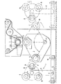
- the upper impression roller 1 and the lower forme cylinder 2 are in their printing position.
- the forme cylinder 2 is mounted in a segment carrier 3 which is pivotable about the bearing axis 4, which is located vertically below the impression cylinder 1 or the printing cylinder 2 in its printing position.
- the segment carrier 3 also carries a pivoted forme cylinder 5 with which printing has already been carried out and which is to be exchanged for a forme cylinder 6 which is located on a carriage 7.
- the carriage 7 consists essentially of an arm 8, which is pivotally pivotable about the axis 9 to both sides on a frame 11 which can be moved on the wheels 10.
- the arm 8 carries a conventional turnstile 12, which is therefore not shown in detail, and which has three receptacles with clamping devices, of which only the clamping device 13 is shown schematically.
- the arm 8 is pivoted clockwise so far that the clamping device 13 can grip the pins of the forme cylinder 5. Then the arm 8 is moved back into its vertical position shown in the drawing. The turnstile 12 is then pivoted through 120 ° clockwise, so that the forme cylinder 6 can be inserted into the receptacle 14 of the segment carrier 13 by pivoting the arm 8 again to the right.
- the carriage 7 carries the removed forme cylinder 5 as well as a further forme cylinder 15.
- the carriage 7 can then be moved from the left machine side of the rotogravure printing machine to its right side. This position is shown with dashed lines. If it is now necessary to remove the forme cylinder 2 and replace it with the forme cylinder 5, only the segment carrier 3 needs to be pivoted about the bearing axis 4 into its right end position, shown in broken lines. Then this swung-out forme cylinder 2 can be held by the clamping device 17, which previously held the forme cylinder 6; lifted out of the bearing 16 of the segment carrier 3 by pivoting the arm 8 of the carriage 7 to the left. Of course, the turnstile 12 has previously been rotated accordingly. The turnstile is then rotated so far that the forme cylinder 15 can be inserted into the holder 16 by pivoting the arm 8 again.
Landscapes
- Engineering & Computer Science (AREA)
- Mechanical Engineering (AREA)
- Rotary Presses (AREA)
- Applications Or Details Of Rotary Compressors (AREA)
Abstract
Description
Die Erfindung betrifft eine Vorrichtung zum Wechseln der Formzylinder in einer Tiefdruckrotationsmaschine mit einem Wagen zum Ein- und Ausfahren der Formzylinder.The invention relates to a device for changing the forme cylinder in a rotogravure printing machine with a carriage for retracting and extending the forme cylinder.
Bei einer aus der DE-PS 26 32 455 bekannten Vorrichtung dieser Art läßt sich jeweils nur ein Formzylinder den geöffneten Lagerschalen der Tiefdruckrotationsmaschine entnehmen oder in diese einlegen, wobei es zusätzlich erforderlich ist, den Wagen durch besondere Einrichtungen so weit in das Gestell der Tiefdruckrotationsmaschine einzuziehen, daß sich die Trageinrichtung des Wagens im Bereich der Lagerschalen befindet,.In a device of this type known from DE-PS 26 32 455, only one forme cylinder can be removed from or inserted into the open bearing shells of the rotogravure printing press, whereby it is additionally necessary to pull the carriage so far into the frame of the rotogravure printing press by special means that the carrying device of the car is in the area of the bearing shells.
Aufgabe der Erfindung ist es daher, eine Vorrichtung der eingangs angegebenen Art zu schaffen, mit der sich schnell und einfach die Formzylinder einer Tiefdruckrotationsmaschine gegen andere austauschen lassen.The object of the invention is therefore to provide a device of the type specified at the outset, with which the forme cylinders of a rotogravure printing machine can be exchanged quickly and easily for others.
Erfindungsgemäß wird diese Aufgabe dadurch gelöst, daß die Formzylinder in Lagerschalen zweier um eine zu deren Achse parallele Achse schwenkbarer Träger oder Tragplatten gelagert sind, daß jeder Träger oder jede Tragplatte mit zwei Lagerschalen versehen ist, die einen gleichen, der Betriebsstellung entsprechenden radialen Abstand von der gemeinsamen Schwenkachse und einen derartigen Abstand voneinander aufweisen, daß sich bei einem in die Betriebsstellung geschwenkten Formzylinder der andere im Bereich einer der Seiten der Maschine befindet, und daß ein an die Maschine ankuppelbarer Wagen vorgesehen ist, der mit mindestens einem zweiarmigen Drehgestell versehen ist, dessen zueinander parallelen Arme mit Aufnahmen für die Formzylinder versehen sind, die zur Entnahme und zum Einlegen der Formzylinder in die ausgeschwenkten Lagerschalen in eine der in diese eingelegten Stellung entsprechende Lage bewegbar sind. Die erfindungsgemäße Vorrichtung ermöglicht insbesondere bei Mehrfarben-Tiefdruckrotationsmaschinen einen schnellen Austausch der Formzylinder, weil bereits vor dem Formzylinderwechsel die für den nächsten Druckvorgang bestimmten Formzylinder in die gut zugänglichen ausgeschwenkten Lagerschalen eingelegt werden können und der den Austausch vornehmende Wagen nicht nur den auszutauschenden Formzylinder den Lagerschalen entnimmt, sondern bereits auch den neu einzulegenden Formzylinder mit sich führt. Ist der Austausch der in den ausgeschwenkten Lagerschalen gelagerten Formzylinder vorgenommen worden, ist es bei einem Formatwechsel oder einem aus anderen Gründen bedingten Wechsel der Formzylinder lediglich notwendig, den in seiner Bereitschaftsstellung befindlichen Formzylinder in seine Druckstellung zu verschwenken, wodurch der zuvor in seiner Druckstellung befindliche Formzylinder ausgeschwenkt wird, so daß auch dieser für den nächstfolgenden Druckvorgang leicht ausgetauscht werden kann.According to the invention this object is achieved in that the forme cylinders are mounted in bearing shells of two supports or support plates which can be pivoted about an axis parallel to their axis, that each support or each support plate is provided with two support shells which have the same radial distance from the operating position have a common pivot axis and such a distance from one another that, when a forme cylinder is pivoted into the operating position, the other is in the region of one of the sides of the machine, and that a carriage which can be coupled to the machine is provided and is provided with at least one two-armed bogie, the arms which are parallel to one another are provided with receptacles for the forme cylinders, which can be moved into a position corresponding to the position inserted in them in order to remove and insert the forme cylinder into the pivoted-out bearing shells. The device according to the invention enables, in particular in multi-color rotogravure printing presses, a quick exchange of the forme cylinders, because even before the forme cylinder change, the forme cylinders intended for the next printing process can be inserted into the easily accessible swiveled-out bearing shells and the carriage carrying out the exchange not only removes the forme cylinder to be exchanged from the bearing shells , but also carries with it the newly inserted form cylinder. If the form cylinders stored in the swiveled-out bearing shells have been replaced, it is only necessary to change the form cylinders or change the form cylinders for other reasons. to pivot the forme cylinder in its ready position into its printing position, whereby the forme cylinder previously in its printing position is pivoted out, so that this can also be easily replaced for the next printing process.
Aus der GB-PS 647 613 ist es bekannt, die Druckzylinder einer Tiefdruckrotationsmaschine an Armen eines mindestens zweiarmigen Drehsterns zu lagern, so daß bei einem Formatwechsel die Druckzylinder schnell gewechselt werden können und der Austausch von Druckzylindern an den nicht in ihrer Drückstellung befindlichen Armen vorgenommen werden kann. Die bekannte Vorrichtung weist jedoch wegen der Lagerung der Druckzylinder in einem Drehstern eine beträchtliche Bauhöhe auf und es ist nicht beschrieben worden, in welcher Weise der Austausch von Formzylindern vorgenommen werden soll, so daß dieses offensichtlich in der herkömmlichen Weise durch Hebezeuge geschieht.From GB-PS 647 613 it is known to store the printing cylinders of a rotogravure printing press on the arms of a rotary arm with at least two arms, so that when changing the format the printing cylinders can be changed quickly and the printing cylinders can be exchanged on the arms that are not in their pressing position can. However, the known device has for the bearing of the printing cylinder in a rotary star, a considerable overall height, and it has not been described, to be carried out in what way the exchange of F ormzylindern so that this in the conventional manner is done obviously by lifting gear.
Vorteilhafte Ausgestaltungen der Erfindung sind in den Unteransprüchen beschrieben worden.Advantageous embodiments of the invention have been described in the subclaims.
Ein Ausführungsbeispiel der Erfindung wird nachstehend anhand der Zeichnung näher erläutert, in deren einziger Figur eine Seitenansicht der Vorrichtung zum Wechseln der Formzylinder schematisch dargestellt ist.An embodiment of the invention is explained in more detail below with reference to the drawing, in the single figure of which a side view of the device for changing the forme cylinder is shown schematically.
Bei der in der Zeichnung dargestellten Tiefdruckmaschine befinden sich der obere Presseur 1 und der untere Formzylinder 2 in ihrer Druckstellung. Der Formzylinder 2 ist in einem Segmentträger 3 gelagert, der um die Lagerachse 4 schwenkbar ist, welche sich lotrecht unterhalb des Presseurs 1 bzw. des in seiner Druckstellung befindlichen Druckzylinders 2 befindet. Der Segmentträger 3 trägt außer dem Formzylinder 2 noch einen ausgeschwenkten Formzylinder 5, mit dem bereits gedruckt worden ist und der gegen einen Formzylinder 6, der sich auf einem Wagen 7 befindet, ausgetauscht werden soll. Der Wagen 7 besteht im wesentlichen aus einem Arm 8, der um die Achse 9 nach beiden Seiten schwenkbar auf einem auf den Rädern 10 verfahrbaren Rahmen 11 gelagert ist. An seinem der Achse 9 gegenüberliegenden Ende trägt der Arm 8 ein übliches und daher nicht näher dargestelltes Drehkreuz 12, welches drei Aufnahmen mit Klemmeinrichtungen besitzt, von denen nur die Klemmeinrichtung 13 schematisch dargestellt ist.In the gravure printing machine shown in the drawing, the upper impression roller 1 and the lower forme cylinder 2 are in their printing position. The forme cylinder 2 is mounted in a
Zum Ausbau des Formzylinders 5 aus dem Segmentträger 3 wird der Arm 8 im Uhrzeigersinn so weit verschwenkt, daß die Klemmeinrichtung 13 die Zapfen des Formzylinder 5 erfassen kann. Danach wird der Arm 8 wieder in seine aus der Zeichnung ersichtliche senkrechte Stellung zurückbewegt. Anschließend wird das Drehkreuz 12 um 120° im Uhrzeigersinn verschwenkt, so daß durch nochmaliges.Schwenken des Arms 8 nach rechts hin der Formzylinder 6 in die Aufnahme 14 des Segmentträgers 13 eingelegt werden kann. Der Wagen 7 trägt den ausgebauten Formzylinder 5 sowie noch einen weiteren Formzylinder 15.To remove the forme cylinder 5 from the
Anschließend kann der Wagen 7 von der linken Maschinenseite der Tiefdruckrotationsmaschine auf deren rechte Seite gefahren werden. Diese Stellung ist mit gestrichelten Linien dargestellt. Ist es nun erforderlich, den Formzylinder 2 auszubauen und gegen den Formzylinder 5 auszutauschen, braucht lediglich der Segmentträger 3 um die Lagerachse 4 in seine rechte, mit gestrichelten Linien dargestellte Endstellung geschwenkt zu werden. Sodann kann dieser ausgeschwenkte Formzylinder2 durch die Klemmeinrichtung 17, die zuvor den Formzylinder 6 gehalten hat; aus der Lagerung 16 des Segmentträgers 3 herausgehoben werden, indem der Arm 8 des Wagens 7 nach links hin geschwenkt wird. Selbstverständlich ist zuvor das Drehkreuz 12 entsprechend der verdreht worden. Im Anschluß wird das Drehkreuz dann so weit verdreht, daß der Formzylinder 15 in die Halterung 16 durch nochmaliges Schwenken des Armes 8 eingelegt werden kann.The carriage 7 can then be moved from the left machine side of the rotogravure printing machine to its right side. This position is shown with dashed lines. If it is now necessary to remove the forme cylinder 2 and replace it with the forme cylinder 5, only the
Während die Druckmaschine bereits wieder arbeitet, können neue Formzylinder in die Halterungen des Drehkreuzes 12 eingelegt werden, nachdem die gebrauchten Formzylinder 2 und 5 beispielsweise mittels eines Kranes aus dem Drehkreuz herausgehoben worden sind. Selbstverständlich wird während der Schwenkbewegung des Segmentträgers 3 der Presseur kurzzeitig in bekannter Weise angehoben.While the printing press is already working again, new forme cylinders can be inserted into the holders of the turnstile 12 after the used forme cylinders 2 and 5 have been lifted out of the turnstile, for example by means of a crane. Of course, the impression roller is briefly raised in a known manner during the pivoting movement of the
Claims (5)
Applications Claiming Priority (2)
| Application Number | Priority Date | Filing Date | Title |
|---|---|---|---|
| DE19823222717 DE3222717A1 (en) | 1982-06-18 | 1982-06-18 | DEVICE FOR REPLACING THE FORM CYLINDERS IN A LOW PRINTING ROTATION MACHINE |
| DE3222717 | 1982-06-18 |
Publications (2)
| Publication Number | Publication Date |
|---|---|
| EP0097331A2 true EP0097331A2 (en) | 1984-01-04 |
| EP0097331A3 EP0097331A3 (en) | 1984-11-14 |
Family
ID=6166229
Family Applications (1)
| Application Number | Title | Priority Date | Filing Date |
|---|---|---|---|
| EP83105886A Withdrawn EP0097331A3 (en) | 1982-06-18 | 1983-06-15 | Device for exchanging forme cylinders in rotary intaglio printing presses |
Country Status (3)
| Country | Link |
|---|---|
| EP (1) | EP0097331A3 (en) |
| JP (1) | JPS5957756A (en) |
| DE (1) | DE3222717A1 (en) |
Cited By (6)
| Publication number | Priority date | Publication date | Assignee | Title |
|---|---|---|---|---|
| EP0467317A1 (en) * | 1990-07-20 | 1992-01-22 | OFFICINE MECCANICHE GIOVANNI CERUTTI S.p.A. | Rotary printing press having an exchangeable pressure roller |
| EP0535452A1 (en) * | 1991-09-27 | 1993-04-07 | OFFICINE MECCANICHE GIOVANNI CERUTTI S.p.A. | Device for introducing the printing cylinder supporting carriages into the printing units of a rotary printing machine |
| EP1593499A1 (en) * | 2004-05-05 | 2005-11-09 | Swipro AG | Device for handling printing cylinder |
| DE102007003975A1 (en) * | 2007-01-26 | 2008-07-31 | Koenig & Bauer Aktiengesellschaft | Printing machine, has transport device that is attached moveably on printing machine, where transport device has single exchange position to exchange roller per movement |
| WO2020143932A1 (en) * | 2019-01-08 | 2020-07-16 | Koenig & Bauer Ag | Application assembly with positioning device and storage device |
| GB2580366A (en) * | 2019-01-04 | 2020-07-22 | Emerson & Renwick Ltd | Roller support |
Families Citing this family (2)
| Publication number | Priority date | Publication date | Assignee | Title |
|---|---|---|---|---|
| DE4328058A1 (en) * | 1993-08-20 | 1995-02-23 | Roland Man Druckmasch | Printing machine with at least one exchangeable cylinder, in particular an exchangeable forme cylinder, or with an exchangeable printing form |
| US5878666A (en) * | 1993-08-20 | 1999-03-09 | Man Roland Druckmaschinen Ag. | Printing machine with at least one interchangeable cylinder |
Citations (2)
| Publication number | Priority date | Publication date | Assignee | Title |
|---|---|---|---|---|
| DE1922274A1 (en) * | 1969-04-30 | 1970-11-12 | Albert Schnellpressen | Device for lifting in and out of forme cylinders on rotogravure rotary machines |
| US3789757A (en) * | 1971-03-26 | 1974-02-05 | Motter J Printing Press Co | Printing press having automatic printing cylinder loading and unloading apparatus |
-
1982
- 1982-06-18 DE DE19823222717 patent/DE3222717A1/en not_active Ceased
-
1983
- 1983-06-15 EP EP83105886A patent/EP0097331A3/en not_active Withdrawn
- 1983-06-17 JP JP10910483A patent/JPS5957756A/en active Pending
Patent Citations (2)
| Publication number | Priority date | Publication date | Assignee | Title |
|---|---|---|---|---|
| DE1922274A1 (en) * | 1969-04-30 | 1970-11-12 | Albert Schnellpressen | Device for lifting in and out of forme cylinders on rotogravure rotary machines |
| US3789757A (en) * | 1971-03-26 | 1974-02-05 | Motter J Printing Press Co | Printing press having automatic printing cylinder loading and unloading apparatus |
Cited By (10)
| Publication number | Priority date | Publication date | Assignee | Title |
|---|---|---|---|---|
| EP0467317A1 (en) * | 1990-07-20 | 1992-01-22 | OFFICINE MECCANICHE GIOVANNI CERUTTI S.p.A. | Rotary printing press having an exchangeable pressure roller |
| EP0535452A1 (en) * | 1991-09-27 | 1993-04-07 | OFFICINE MECCANICHE GIOVANNI CERUTTI S.p.A. | Device for introducing the printing cylinder supporting carriages into the printing units of a rotary printing machine |
| EP1593499A1 (en) * | 2004-05-05 | 2005-11-09 | Swipro AG | Device for handling printing cylinder |
| DE102007003975A1 (en) * | 2007-01-26 | 2008-07-31 | Koenig & Bauer Aktiengesellschaft | Printing machine, has transport device that is attached moveably on printing machine, where transport device has single exchange position to exchange roller per movement |
| DE102007003975B4 (en) | 2007-01-26 | 2021-08-12 | Koenig & Bauer Ag | Aggregate printing press with units arranged in a row |
| GB2580366A (en) * | 2019-01-04 | 2020-07-22 | Emerson & Renwick Ltd | Roller support |
| WO2020143932A1 (en) * | 2019-01-08 | 2020-07-16 | Koenig & Bauer Ag | Application assembly with positioning device and storage device |
| CN114126876A (en) * | 2019-01-08 | 2022-03-01 | 柯尼格及包尔公开股份有限公司 | Inking assembly with positioning device and storage device |
| US11318731B2 (en) | 2019-01-08 | 2022-05-03 | Koenig & Bauer Ag | Application unit with positioning device and magazine |
| CN114126876B (en) * | 2019-01-08 | 2022-11-25 | 柯尼格及包尔公开股份有限公司 | Inking assembly with positioning device and storage device |
Also Published As
| Publication number | Publication date |
|---|---|
| DE3222717A1 (en) | 1983-12-22 |
| EP0097331A3 (en) | 1984-11-14 |
| JPS5957756A (en) | 1984-04-03 |
Similar Documents
| Publication | Publication Date | Title |
|---|---|---|
| DE4413807C1 (en) | Device for changing the cylinders on a printing press | |
| EP0128487B1 (en) | Machine-tool having a stationary magazine | |
| DE1777348C3 (en) | Changing device for a tool support of a punching press that accommodates the upper movable punching tool | |
| DE10022269B4 (en) | Method and device for carrying out a product change in thermoforming processes | |
| DE19843889B4 (en) | Punching tool storage and changing system | |
| DE3440224C2 (en) | Tool changing device on a punching or nibbling machine | |
| DE2700502A1 (en) | MULTI-STAGE PRESS | |
| DE2512613C2 (en) | Suction gripping device for gripping and handling a cuboid body | |
| EP0290853A2 (en) | Bearing for a printing unit cylinder | |
| EP0097331A2 (en) | Device for exchanging forme cylinders in rotary intaglio printing presses | |
| DE69613976T2 (en) | METHOD AND DEVICE FOR RELEASING CATHODE PLATES | |
| DE19856517C2 (en) | Device for exchanging rolls in a calender | |
| DE2751971C2 (en) | ||
| DE2740042C2 (en) | Tool changing device in a multi-stage massive forming press | |
| DE930145C (en) | Device for setting up printing plates | |
| EP0567906A1 (en) | Device for adjusting a doctor blade holding against an ink releasing cylinder of a rotary web printing machine | |
| DE2738081C2 (en) | Tool changing device on a press | |
| DE3141604C2 (en) | ||
| DE69506031T2 (en) | Changing device for the tools of a cutting device | |
| DE4238672A1 (en) | ||
| DE3239482C2 (en) | ||
| EP0478903A1 (en) | Device for changing cassettes for a web-fed rotary press | |
| DE732687C (en) | Device for changing the forme cylinder of rotogravure printing machines | |
| DE3201447C1 (en) | Device for changing model plates in molding machines | |
| DE650392C (en) | Anil printing machine |
Legal Events
| Date | Code | Title | Description |
|---|---|---|---|
| PUAI | Public reference made under article 153(3) epc to a published international application that has entered the european phase |
Free format text: ORIGINAL CODE: 0009012 |
|
| AK | Designated contracting states |
Designated state(s): CH FR GB IT LI |
|
| PUAL | Search report despatched |
Free format text: ORIGINAL CODE: 0009013 |
|
| AK | Designated contracting states |
Designated state(s): CH FR GB IT LI |
|
| STAA | Information on the status of an ep patent application or granted ep patent |
Free format text: STATUS: THE APPLICATION IS DEEMED TO BE WITHDRAWN |
|
| 18D | Application deemed to be withdrawn |
Effective date: 19850715 |
|
| RIN1 | Information on inventor provided before grant (corrected) |
Inventor name: LUEBKE, HERBERT Inventor name: STASCHEIT, WINFRIED |