EP0096485A2 - Automatische Verteilvorrichtung für biegsame Scheiben - Google Patents
Automatische Verteilvorrichtung für biegsame Scheiben Download PDFInfo
- Publication number
- EP0096485A2 EP0096485A2 EP83302806A EP83302806A EP0096485A2 EP 0096485 A2 EP0096485 A2 EP 0096485A2 EP 83302806 A EP83302806 A EP 83302806A EP 83302806 A EP83302806 A EP 83302806A EP 0096485 A2 EP0096485 A2 EP 0096485A2
- Authority
- EP
- European Patent Office
- Prior art keywords
- carrier
- disc
- plunger
- dispenser according
- piston
- Prior art date
- Legal status (The legal status is an assumption and is not a legal conclusion. Google has not performed a legal analysis and makes no representation as to the accuracy of the status listed.)
- Withdrawn
Links
Images

Classifications
-
- H—ELECTRICITY
- H01—ELECTRIC ELEMENTS
- H01B—CABLES; CONDUCTORS; INSULATORS; SELECTION OF MATERIALS FOR THEIR CONDUCTIVE, INSULATING OR DIELECTRIC PROPERTIES
- H01B13/00—Apparatus or processes specially adapted for manufacturing conductors or cables
- H01B13/012—Apparatus or processes specially adapted for manufacturing conductors or cables for manufacturing wire harnesses
Definitions
- This invention relates to the dispensing of flexible discs and particularly to an automatic dispenser which is capable of dispensing flexible discs one at a time so as to fit or force each disc over a spigot or, preferably, a shouldered pin such as may be used in the production of a wiring loom for electrical harnesses.
- a loom table or pins used in conjunction with it or a method of using such a table is not part of the present invention, a preferred form of the present invention is intended to be suitable for use in a technique of producing wiring harnesses as is described, for example, in our European Patent Application No. 82301173.9 (published 13 October 1982 under No. 0062413).
- a loom table includes, among other things, a multiplicity of layers of which one is a mesh that can receive the ends of shouldered pins but which prevents the complete passage of the pins.
- the pins are inserted in predetermined positions so as to define a multiplicity of paths for the wires which are to be laid down to form the wiring harness.
- an automatic robot manipulator for the insertion of the pins in the table and to lay the wires using the same manipulator which may have a wrist coupled to a pneumatic line and adapted for the reception of a multiplicity of different devices such as a pin insertion tool and a wire laying tool.
- the pins may be disposed in pairs, the path or paths of the wires extending between the pairs.
- the pins are preferably double ended, having a central portion of larger diameter and two similar end portions of reduced diameter. Accordingly, a collar may be inserted over the upper end of the pin and be supported by the shoulder at one end of the central portion. It is one object of the present invention to provide an automatic dispenser which can place a collar on such a pin.
- the dispenser is adapted for coupling to a pneumatic line and is intended for use as a detachable accessory tool for a robot; for this purpose the coupling by means of which the dispenser is attachable to a robot head may be of a convenient standard form.
- other forms of coupling may be used if the circumstances permit.
- the automatic manipulator may use a head which is in the form of a tube of annular cross-section, this tube being coupled when in place on the manipulator to a source of vacuum suction so that it can pick-up a collar and deposit it over the head of a pin.
- a source of vacuum suction so that it can pick-up a collar and deposit it over the head of a pin.
- British Patent Specification No. 1252355 illustrates a mechanism for transferring punched cards one at a time from one stack to another by means of a slider and a plunger.
- British Patent Specification No. 1481996 illustrates a machine in which metal fasteners are fed in single file, though not in a stack, to a transfer position whence one can be engaged by a plunger while a second fastener is held away from the pa:h of the plunger.
- Neither specification is concerned with the dispensing of discs onto pins or spigots.
- a further more specific object of the invention is to provide a dispenser which is capable of dispensing a flexible collar over a pin or spigot.
- a dispenser comprises a magazine for a stack of discs and a carrier which is.adapted to receive a single disc from one end of the stack and capable of releasing such a disc on the application of axial force thereto.
- the dispenser further comprises means for moving the carrier so as to align the disc with a plunger, preferably a hollow plunger if the discs are in the form of collars for disposition over pins or spigots. Means are provided for advancing the plunger to apply the required axial force to release the disc from the carrier.
- the carrier includes an aperture for accommodating a disc and means,such as a partial shoulder, for engaging the disc at the rim thereof in order to resist but not prevent axial movement of the disc relative to the carrier.
- the carrier comprises a plate positioned to cover the.said one end of the stack and being movable between a position for receiving the disc and a position generally aligning the disc with respect to the plunger.
- the means for moving the carrier is largely dependent upon the nature of the carrier and the movement thereof.
- the carrier might be a slidable plate, it is preferable to provide a carrier which rotates between the aforementioned positions.
- the means for moving the carrier may include a piston or plunger keyed to prevent its rotation and including means such as a pin adapted to engage a helical groove in a spigot which is secured to the carrier for conjoint rotation therewith.
- the means for moving the carrier and the means for advancing the hollow plunger may be constituted by resettable actuators.
- the actuator for moving the carrier may be constituted by a piston movable against a restoring force provided by a spring.
- the actuator for the hollow plunger may likewise comprise a piston which may be movable against a restoring force provided by a spring. It is convenient to provide sequencing of the operation of the actuators so that the actuator for the carrier completes the movement of the carrier and such that the movement of the hollow plunger is inhibited until the carrier's movement is completed.
- the piston for effecting movement of the carrier may be arranged to inhibit the communication of the piston for moving the hollow plunger with a source of fluid pressure until the stroke of the piston for moving the carrier is substantially completed.
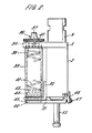
- the drawings illustrate a dispenser 1 which has a metal body 2 which may be made of aluminium. With reference particularly to Figure l,within the body are two passageways 3 and 4 which may be formed by boring or reaming whichever is convenient.
- the body 2 has a top plate 5 which closes off the top end of the passageway 3, which at its upper end is slightly enlarged for the accommodation of an O-ring 6.
- the plate 5 has an aperture 7 aligned with the passageway 4, which is slightly enlarged at its upper end for the accommodation of an O-ring 8.
- Fitting within the aperture 7 is a coupling 9 having an internal passageway 10 and a bayonet fitting 11 by means of which the coupling 9 may be connected to a standard pneumatic hand or wrist of a robot manipulator.
- the passageway 10 can receive pneumatic pressure at times determined by the programming of the manipulator. This form of manipulator is well-known and will not be described further.
- the entrance to this passage from the passageway 3 is normally below the head of the piston 14 and thus until the piston substantially completes its stroke the chamber constituted by the passageway 4 is cut-off from communication with the source of pneumatic pressure.
- a pivot bearing 20 Within a lower, reduced section, part 19 of the passageway 3 is fitted a pivot bearing 20 .
- the bearing 20 has an external screw threading 21 for engagement with a threading in the part 19.
- the upper part of the bearing is formed as a tube 22 which receives the stem 15 of the piston.
- a compression spring 23 Within the annular well formed between the tube 22 and the wall of the passageway 3 is a compression spring 23 which provides restoring force for the piston.
- an air hole 24 formed in the body 2. This air hole permits the escape of air from that part of the chamber 3 which is below the head of the piston 14.
- the upper tubular part 22 of the bearing includes a slot 25 which is arranged so as to extend lengthwise of the stem 15 of the piston. This slot is engaged by one end of a pin 26 carried in the aperture 16 in the stem 15 of the piston 14.
- the pin 26 and the slot 25 provide a means of keying the piston and thereby preventing rotation thereof.
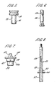
- a spigot 28 which extends upwardly so as to be accommodated within the hollow stem 15 of the piston.
- the spigot 28, which is shown in detail in Figure 6, is formed with a helical groove 29 engaged by the inner end of the pin 26.
- a carrier 31 is attached to the spigot 28.
- This carrier 31 is in the form of a plate arranged in a plane generally transverse the direction of movement and the longitudinal axis of the piston.
- the piston and the components associated therewith constitute a resettable actuator for moving the carrier constituted by the plate 31.
- Downward movement of the piston in response to the application of fluid pressure to the passageway 10 causes the spigot 28 to rotate and thereby causes the plate 31 to rotate to the position shown in Figure 1.
- the carrier moves to this position from a position which it can receive a disc from a stack of discs.
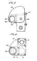
- Figure 2 illustrates the dispenser when the carrier is in a position to receive a disc, and the features of Figure 2 will be for convenience described before the remainder of Figure 1.
- a bracket 32 supporting the bottom end of a magazine 33 constituted by a metal tube.
- the upper end of the magazine 33 is aligned with an aperture 34 in the top plate and this aperture is provided with recesses 35 constituting part of a bayonet fitting for a closure 36.
- the closure has an external grip 37 and a cylindrical body 38 which has a lateral bore 39 supporting a nylon pin 40 ( Figure 2) which can engage the recesses 35.
- the body 38 has an annular shoulder 41 and associated groove 41a supporting one end of a compression spring 42 of which the other end engages a metal pressure pad 43. This pad bears on the upper end of a stack of rubber collars 44, and together with the spring constitutes means for urging the stack towards the lower end of the magazine.
- the magazine may readily be loaded with a stack of discs by removing the closure 36 together with the spring 42 and pad 43.
- the carrier 31 includes a shallow recess 45 which is of depth approximately corresponding to the depth of a collar and of diameter slightly larger than that of a collar 44.
- the recess is formed with a peripheral shoulder 46. Other forms of shoulder could be used instead.
- the lowermost disc in the stack is received by the recess 45.
- the recess 45 and shoulder 46 provide a means by which a collar or disc can be received and they inhibit but, owing to the slightness of the shoulder, do not prevent the passage of the disc through the carrier 31 if sufficient axial force is applied to the collar which is in the recess 45.
- the force of the spring 42 must be sufficient to maintain the stack of discs but should be insufficient to force the lowermost collar through the carrier plate 31. Xowever, quite a strong . spring 42 can be used because in the arrangement shown it is difficult for the lowermost disc to flex as is required for its passage through the aperture defined by the shoulder 46.
- the return position of the carrier 34 is set by an adjustable stop 47 carried on a bracket 48 . attached to the body 2.
- the head 50 is secured to the top of a stem 51 of which the lower part 52 constitutes a hollow plunger, there being a bore 53 extending from the lower end of the stem 51 towards the upper end thereof.
- the lower end of the stem 51 is enlarged, having a head 54. This provides an end stop for the upward movement of the piston head 50.
- the head 50 is urged upwardly by means of a compression spring 55 engaging the head 50 and encircling the stem 51.
- the passageway 4 is provided with an air relief hole 56.
- the pistons retract automatically when the fluid pressure is relieved, and it will be noted that the recess 45 is open at one side (shown by the reference 59) so that the carrier can return without fouling the plunger 52.
- dispenser in its preferred form, intended for use as particularly described, it may have a more general utility.
Landscapes
- Engineering & Computer Science (AREA)
- Manufacturing & Machinery (AREA)
- Manipulator (AREA)
- De-Stacking Of Articles (AREA)
- Coating Apparatus (AREA)
- Containers And Packaging Bodies Having A Special Means To Remove Contents (AREA)
Applications Claiming Priority (2)
| Application Number | Priority Date | Filing Date | Title |
|---|---|---|---|
| GB8216577 | 1982-06-08 | ||
| GB8216577 | 1982-06-08 |
Publications (2)
| Publication Number | Publication Date |
|---|---|
| EP0096485A2 true EP0096485A2 (de) | 1983-12-21 |
| EP0096485A3 EP0096485A3 (de) | 1985-10-23 |
Family
ID=10530885
Family Applications (1)
| Application Number | Title | Priority Date | Filing Date |
|---|---|---|---|
| EP83302806A Withdrawn EP0096485A3 (de) | 1982-06-08 | 1983-05-17 | Automatische Verteilvorrichtung für biegsame Scheiben |
Country Status (3)
| Country | Link |
|---|---|
| EP (1) | EP0096485A3 (de) |
| JP (1) | JPS5957829A (de) |
| GB (1) | GB2121387A (de) |
Family Cites Families (4)
| Publication number | Priority date | Publication date | Assignee | Title |
|---|---|---|---|---|
| FR888151A (fr) * | 1942-07-17 | 1943-12-06 | Pour Liaisons Telephoniques & | Machine automatique pour la fabrication d'éléments de câbles à conducteurs concentriques |
| GB641037A (en) * | 1948-05-07 | 1950-08-02 | Telecommunications Sa | Machines for making high frequency cables |
| FR1024537A (fr) * | 1950-09-13 | 1953-04-02 | Telecommunications Sa | Perfectionnements à la constrcution des paires concentriques |
| GB2095135B (en) * | 1981-03-25 | 1984-09-26 | Lansing Bagnall Ltd | Production of wiring harnesses |
-
1983
- 1983-05-17 EP EP83302806A patent/EP0096485A3/de not_active Withdrawn
- 1983-05-17 GB GB08313601A patent/GB2121387A/en not_active Withdrawn
- 1983-06-08 JP JP10251383A patent/JPS5957829A/ja active Pending
Also Published As
| Publication number | Publication date |
|---|---|
| GB2121387A (en) | 1983-12-21 |
| EP0096485A3 (de) | 1985-10-23 |
| GB8313601D0 (en) | 1983-06-22 |
| JPS5957829A (ja) | 1984-04-03 |
Similar Documents
| Publication | Publication Date | Title |
|---|---|---|
| EP0491193B1 (de) | Automatische Nietzufuhrvorrichtung | |
| CA1283635C (en) | Apparatus for installing fasteners | |
| EP0092967A2 (de) | Automatische Greifhand-Wechselvorrichtung für Industrieroboter | |
| US5375754A (en) | Automatic riveting machine | |
| EP0073127A2 (de) | Spannzangentyp-Bohrmaschine | |
| EP0201293B1 (de) | Setzgerät für Blindniete mit Abbrechschaft | |
| US12275056B2 (en) | Device for setting a temporary fastener | |
| JP2023538484A (ja) | リベット設定デバイス | |
| US4620079A (en) | Stud welding device | |
| US4442738A (en) | Automatic push-to-start screwdriver | |
| JP2023538719A (ja) | コーティングデバイス | |
| US4630344A (en) | Apparatus and method for assembling parts | |
| EP0096485A2 (de) | Automatische Verteilvorrichtung für biegsame Scheiben | |
| US5647111A (en) | Automatic sealant application apparatus and method | |
| US4352615A (en) | Feeder for automatic lathe | |
| US4351684A (en) | Pneumatically operated applicator and method of applying adhesive tape | |
| US5297417A (en) | Portable collet crimping apparatus | |
| JPS61159347A (ja) | ロボツト手段によつて支持されるドリルユニツトのドリルビツト組立体を自動的に交換するための装置 | |
| US4365400A (en) | Apparatus for installing sleeves on substrates | |
| JPH0250819B2 (de) | ||
| US4451965A (en) | Method for installing a sleeve on a substrate | |
| JP2004344980A (ja) | 遠隔式ファスナ送出装置 | |
| US5572915A (en) | Pull bar gripper assembly | |
| US2390318A (en) | Rivet ejector | |
| EP0178117B1 (de) | Bolzenschweissvorrichtung |
Legal Events
| Date | Code | Title | Description |
|---|---|---|---|
| PUAI | Public reference made under article 153(3) epc to a published international application that has entered the european phase |
Free format text: ORIGINAL CODE: 0009012 |
|
| AK | Designated contracting states |
Designated state(s): AT BE CH DE FR IT LI LU NL SE |
|
| PUAL | Search report despatched |
Free format text: ORIGINAL CODE: 0009013 |
|
| AK | Designated contracting states |
Designated state(s): AT BE CH DE FR IT LI LU NL SE |
|
| STAA | Information on the status of an ep patent application or granted ep patent |
Free format text: STATUS: THE APPLICATION IS DEEMED TO BE WITHDRAWN |
|
| 18D | Application deemed to be withdrawn |
Effective date: 19851202 |
|
| RIN1 | Information on inventor provided before grant (corrected) |
Inventor name: GIBBONS, RALPH DAVID |