EP0096110B1 - Fiberglass reinforced cooling tower - Google Patents
Fiberglass reinforced cooling tower Download PDFInfo
- Publication number
- EP0096110B1 EP0096110B1 EP82109736A EP82109736A EP0096110B1 EP 0096110 B1 EP0096110 B1 EP 0096110B1 EP 82109736 A EP82109736 A EP 82109736A EP 82109736 A EP82109736 A EP 82109736A EP 0096110 B1 EP0096110 B1 EP 0096110B1
- Authority
- EP
- European Patent Office
- Prior art keywords
- cooling tower
- side panels
- further characterized
- panels
- extending
- Prior art date
- Legal status (The legal status is an assumption and is not a legal conclusion. Google has not performed a legal analysis and makes no representation as to the accuracy of the status listed.)
- Expired
Links
Images


Classifications
-
- F—MECHANICAL ENGINEERING; LIGHTING; HEATING; WEAPONS; BLASTING
- F28—HEAT EXCHANGE IN GENERAL
- F28F—DETAILS OF HEAT-EXCHANGE AND HEAT-TRANSFER APPARATUS, OF GENERAL APPLICATION
- F28F21/00—Constructions of heat-exchange apparatus characterised by the selection of particular materials
- F28F21/06—Constructions of heat-exchange apparatus characterised by the selection of particular materials of plastics material
-
- F—MECHANICAL ENGINEERING; LIGHTING; HEATING; WEAPONS; BLASTING
- F28—HEAT EXCHANGE IN GENERAL
- F28C—HEAT-EXCHANGE APPARATUS, NOT PROVIDED FOR IN ANOTHER SUBCLASS, IN WHICH THE HEAT-EXCHANGE MEDIA COME INTO DIRECT CONTACT WITHOUT CHEMICAL INTERACTION
- F28C1/00—Direct-contact trickle coolers, e.g. cooling towers
-
- Y—GENERAL TAGGING OF NEW TECHNOLOGICAL DEVELOPMENTS; GENERAL TAGGING OF CROSS-SECTIONAL TECHNOLOGIES SPANNING OVER SEVERAL SECTIONS OF THE IPC; TECHNICAL SUBJECTS COVERED BY FORMER USPC CROSS-REFERENCE ART COLLECTIONS [XRACs] AND DIGESTS
- Y02—TECHNOLOGIES OR APPLICATIONS FOR MITIGATION OR ADAPTATION AGAINST CLIMATE CHANGE
- Y02B—CLIMATE CHANGE MITIGATION TECHNOLOGIES RELATED TO BUILDINGS, e.g. HOUSING, HOUSE APPLIANCES OR RELATED END-USER APPLICATIONS
- Y02B30/00—Energy efficient heating, ventilation or air conditioning [HVAC]
- Y02B30/70—Efficient control or regulation technologies, e.g. for control of refrigerant flow, motor or heating
-
- Y—GENERAL TAGGING OF NEW TECHNOLOGICAL DEVELOPMENTS; GENERAL TAGGING OF CROSS-SECTIONAL TECHNOLOGIES SPANNING OVER SEVERAL SECTIONS OF THE IPC; TECHNICAL SUBJECTS COVERED BY FORMER USPC CROSS-REFERENCE ART COLLECTIONS [XRACs] AND DIGESTS
- Y10—TECHNICAL SUBJECTS COVERED BY FORMER USPC
- Y10S—TECHNICAL SUBJECTS COVERED BY FORMER USPC CROSS-REFERENCE ART COLLECTIONS [XRACs] AND DIGESTS
- Y10S261/00—Gas and liquid contact apparatus
- Y10S261/11—Cooling towers
Landscapes
- Engineering & Computer Science (AREA)
- Mechanical Engineering (AREA)
- General Engineering & Computer Science (AREA)
- Physics & Mathematics (AREA)
- Thermal Sciences (AREA)
- Heat-Exchange Devices With Radiators And Conduit Assemblies (AREA)
- Separation By Low-Temperature Treatments (AREA)
- Sampling And Sample Adjustment (AREA)
- Sewage (AREA)
Abstract
Description
- The present invention relates to a liquid cooling tower according to the precharacterising part of patent claim 1. The cooling tower of that kind is disclosed in US-A-4 309 365.
- Cooling towers are used to cool liquid by contact with air. The liquid is allowed to flow downwardly through the tower, and a counter current flow of air is drawn through the falling liquid by various means. A common application of liquid cooling towers is for cooling water (dissipating waste heat) used in electrical generating and process plants and industrial and institutional air conditioning systems.
- Most cooling towers include a tower structure which encloses a fill material. The fill material has spaces through which the liquid flows downwardly and the air flows upwardly to provide heat and mass transfer between the liquid and the air. The tower structure may be formed from concrete, metal or other material.
- Metal parts of cooling towers can be corrected by the local atmosphere and/or the liquid which is being cooled. Concrete is very durable, but concrete towers are expensive and heavy. Many cooling towers are located on roofs of buildings, and the weight of a concrete cooling tower can cause building design problems.
- Plastic parts are resistant to corrosion, but plastic parts ordinarily would not provide enough strength to support the fill material and the weight of the tower itself. One well known type of fill material consists of stacked layers of open-celled clay tiles. This fill material can weigh 60,000 to 70,000 pounds for a conventional size air conditioning cooling tower. Plastic structural parts of a cooling tower must not only support the weight of the fill material but must also resist wind forces and should be designed to withstand earthquake loads. We are not aware of any cooling towers whose structural parts are formed completely of plastic.
- In the above-mentioned US-A-4 309 365 a non-corrosive, non-staining evaporative cooler cabinet is disclosed comprising of reaction injection molded elements of high modulous urethane elastomer. The production of such parts is very expensive if their dimensions are those of cooling towers as molds of considerable size are required therefore. Furthermore, the kind of material raises some problems with respect to life, especially when exposed to light containing a high amount of ultraviolet components.
- It is an object of the invention to provide a cooling tower consisting of non-corrosive, non-staining parts of good resistance to the influences of the environment.
- This object is attained by the characterising features of patent claim 1. Further embodiments of the invention are the subject matter of the subclaims.
- According to the invention, the cooling tower is formed from fibreglass reinforced polyester resin panels and beams.
- All of the structural parts of the tower are fibreglass reinforced plastic except the cast iron lintels which are used to support the fill material and stainless steel bolts which connect the fibreglass reinforced polyester parts. The panels are formed to distribute the load of the tower, the fill material, and the liquid basin to the corners and inlet columns of the tower, and the panels are reinforced with unidirectional glass fibers in critical areas to provide sufficient structural strength. A fan is positioned within a fan shroud in the top of the tower, and the fan and the fan motor are supported by the shroud. Since the fan and the shroud move together if the motor vibrates, the clearance between the fan and the shroud can be minimised, thereby increasing the efficiency of the tower.
- The invention will be explained in conjunction with an illustrative embodiment shown in the accompanying drawing, in which-
- Fig. 1 is a perspective view, partially broken away, of a cooling tower formed in accordance with the invention;
- Fig. 2 is an exploded side view of the liquid basin, one side panel, and the top assembly;
- Fig. 3 is a sectional view of the top assembly;
- Fig. 4 is an exploded sectional view of the top assembly;
- Fig. 5 is a perspective view showing the assembly of the tower after two side panels and two cross beams have been erected;
- Fig. 6 is a perspective view showing a subsequent stage in erecting the tower;
- Fig. 7 is a perspective view of the liquid basin;
- Fig. 8 is a fragmentary perspective view showing the tower being filled with fill material;
- Fig. 8A is an enlarged fragmentary perspective view of the end of a support lintel and a pair of clay tiles;
- Fig. 9 is a fragmentary sectional view of the fan shroud taken along the line 10-10 of Fig. 4;
- Fig. 10 is an enlarged fragmentary sectional view of a portion of Fig. 4;
- Fig. 11 is a top plan view of the fan support spider;
- Fig. 12 is a sectional view taken along the line 12-12 of Fig. 11;
- Fig. 13 is a sectional view taken along the line 13-13 of Fig. 11;
- Fig. 14 is a top plan view of the fan deck;
- Fig. 15 is a fragmentary sectional view taken along the line 15-15 of Fig. 14;
- Fig. 16 is a fragmentary sectional view taken along the line 16-16 of Fig. 14;
- Fig. 17 is an enlarged fragmentary sectional view taken along the line 17-17 of Fig. 14;
- Fig. 18 is an enlarged sectional view of one of the top panels shown in Fig. 4;
- Fig. 19 is a sectional view of one of the top panels taken along the line 19-19 of Fig. 4 showing the header support;
- Fig. 20 is a sectional view of the corner portion of one of the top panels taken along the line 20-20 of Fig. 2;
- Fig. 21 is a sectional view of the corner portion of one of the top panels taken along the line 21-21 of Fig. 2;
- Fig. 22 is a side elevational view of one of the side panels;
- Fig. 23 is a sectional view of the side panel taken along the line 23-23 of Fig. 22;
- Fig. 24 is a sectional view taken along the line 24-24 of Fig. 22;
- Fig. 25 is a sectional view of the corner portion of the side panel taken along the line 25-25 of Fig. 22;
- Fig. 26 is a sectional view of the corner portion of the side panel taken along the line 26-26 of Fig. 22;
- Fig. 27 is a sectional view of the corner portion of the side panel taken along the line 27-27 of Fig. 22;
- - Fig. 28 is an elevational view of one of the other side panels;
- Fig. 29 is a sectional view taken along the line 29-29 of Fig. 28;
- Fig. 30 is a fragmentary sectional view of the corner portion of the side panel taken along the line 30-30 of Fig. 28;
- Fig. 31 is a fragmentary sectional view of the corner portion of the side panel taken along the line 31-31 of Fig. 28;
- Fig. 32 is a sectional view showing the corner portions of two adjacent side panels joined together as would be seen along the line 32-32 of Fig. 1;
- Fig. 33 is a sectional view showing the corner portions of two adjacent side panels joined together as would be seen along the line 33-33 of Fig. 1 and 28;
- Fig. 34 is a side elevational view of one of the cross beams;
- Fig. 35 is a top plan view of the cross beams;
- Fig. 36 is an enlarged sectional view taken along the line 36-36 of Fig. 34;
- Fig. 37 is a sectional view taken along the line 37-37 of Fig. 36;
- Fig. 38 is a fragmentary sectional view of the liquid basin;
- Fig. 39 is a fragmentary sectional view of the liquid basin taken along the line 39-39 of Fig. 38;
- Fig. 40 is a top plan view, partially broken away, of the liquid distribution assembly;
- Fig. 41 is a side elevational view of the liquid distribution assembly;
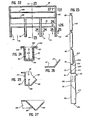
- Fig. 42 is a fragmentary side elevational view of one of the support lintels for the fill material;
- Fig. 43 is an end elevational view of the support lintel;
- Fig. 44 is an enlarged top plan view of one of the clay tiles whih comprise the fill material;
- Fig. 45 is a side elevational view of the clay tiles;
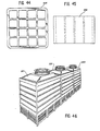
- Fig. 46 is a perspective view showing a plurality of modular cooling towers joined to provide a large capacity tower;
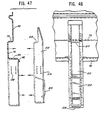
- Fig. 47 is a fragmentary exploded sectional view of the side panel and channel-shaped insert of Fig. 23; and
- Fig. 48 is a fragmentary elevational view of the assembled side panel and insert of Fig. 47.
- Referring first to Fig. 1, the numeral 50 designates generally a mechanical draft type of cooling tower which is used for cooling water for an air conditioning system. The cooling tower includes a
liquid basin 51 at the bottom of the tower, four vertically extendingside panels side panels side panels - The top assembly includes a
liquid distribution assembly 61 for feeding the liquid which is to be cooled to the top of the fill material and afan 62 for drawing air through the fill material countercurrently with the flow of liquid. The fan is mounted in aspider support 63 which is attached to a generallycylindrical fan shroud 64, and the fan is driven by amotor 65 which is also mounted on the spider. Air is drawn through the bottom of the fill material from outside of the cooling tower throughlouvers 66 which are mounted in theside panels drift eliminator assembly 67 is positioned between the fan and theliquid distribution assembly 61. The drift eliminator assembly is intended to permit air to flow upwardly there through but to impede the water. The particular drift eliminator shown in the drawing uses three layers of angled slots to form a zigzag path. Another type of drift eliminator which could be used includes a plurality of spaced-apart air-foil shaped vanes. - Each of the side panels 52-55 is formed from fiberglass reinforced polyester resin. The outer surface of each side panel preferably includes a protective gel coat, and the panel can be formed by spraying a mold with a conventional gel coat, laying glass fibers over the gel coat, and applying a conventional polyester resin. The fiberglass is preferably woven roving, and, as will be explained more fully hereinafter, portions of the side panels are reinforced with unidirectional fiberglass to provide additional structural strength in certain critical areas.
- The
side panels main panel portion 70, a pair of generally channel-shapedlegs box section 75 which extends across the entire length of the panel and which merges into the corner posts. The panel is recessed between the corner posts 73 and 74 and thelegs air intake openings 76. - Referring to Fig. 23, the
beam 75 includes upper andlower ledges central portion 81. The lower ledge terminates in a downwardly and inwardly extendinglip 82 which directs water away from the air openings. - The upper end of each
side panel channel 83. A pair of reinforcingribs 84 and 85 extend parallel to the upper rib and to thebeam 75. - Referring to Fig. 25, each corner post includes an outwardly extending
side wall 87, anouter wall 88, and anangled corner wall 89 which extends at about 45° with respect to the plane of thewall 88. Abottom wall 90 at the bottom of the post is provided with bolt holes 91 for bolting the post to an I beam, concrete curb, etc. which supports the tower. - Referring now to Fig. 26, each lateral end of the
beam 75 terminates in anangled corner wall 89 which is a continuation of theangled corner wall 89 of the corner post. Fig. 27 shows that each lateral end of the upper portion of theside panels wall 93 which includes anangled corner portion 89 which is a continuation of theangled corner wall 89 of the beam. A continuous angled wall is thereby provided at each corner of the cooling tower which extends at about 45° with respect to the two adjacent side panels of the cooling tower and which can be connected to a similar angled wall on the adjacent panel to provide the cooling tower with generally channel-shaped corners. This will be explained more fully hereinafter. - As can be seen in Fig. 24, each channel-shaped
leg parallel side walls outer wall 99, and abottom wall 100. The side walls terminate in laterally flaredflanges 101 and 102. Thebottom wall 100 is provided with bolt holes 104 for bolting the leg to a supporting I beam or curb. Theside walls lower ledge 80 of thebeam 75, and theouter wall 99 is flush with theouter wall 81 of the beam (see Fig. 23). - Each of the
side panels 53 and 55 (Figs. 28-31) are made from the same mold. Theside panels side panels side panels side panels side panels - Each
side panel main panel portion 106 and a pair of vertically extendingcorner portions beam section 109 and horizontally extending reinforcing ribs orchannels beam 109. Thebeam 109 includes upper andlower ledges 116 and 117 (Fig. 29) and anouter wall 118. - The shape of the corner posts 107 and 108 below the
beam 109 is shown in Fig. 30. Each corner post includes an L-shapedwall 119 which includes anangled corner wall 120 which extends at 45° with respect to the two adjacent side panels at the corner. Thebottom flange 113 is provided with abolt hole 121. The corner post has the same configuration above thebeam 109, as shown in Fig. 31. Fig. 33 shows the shape of the corner post where thebeam 109 merges with the corner. Theouter wall 118 of the beam merges directly into theangled corner wall 120. - The
angled corner wall 120 extends for the entire height of theside panels side panels angled corner wall 89 of one of theside panels corner walls stainless steel bolts 122 which are spaced apart about 5 or 6 inches (127 or 152 mm). The corners of the cooling tower above and below thebeam sections - Returning to Fig. 29, the
lower edge 117 of thebeam 109 is provided with an upwardly raised ridge orlip 123, which may be formed from glass fibers and resin. A plurality of cast iron support lintels 59 (Figs. 8 and 8A) are supported at one end by thelower ledge 117 and at the other end by one of the cross beams 57 and 58. Referring to Figs. 8A, 42, and 43, each lintel has an inverted T shape, and each end of the lintel includes a downwardly extendingflange 124. Theflange 124 is engageable with thelip 123 on theledge 117 to prevent the end of the lintel from being withdrawn from the ledge. - A reinforcing bar or stiffener 125 (Figs. 28 and 30) is secured to the
side panels stiffener 125 includes acore 126 of polyurethane foam and anouter skin 127 of fiberglass reinforced polyester resin which is joined to the resin of the panel. - The cross-beams 57 and 58 are formed completely from fiberglass reinforced polyester resin. Each beam includes an inverted channel-shaped wall 130 (Fig. 36), a plurality of bulkheads or
panels 131, and abottom wall 132. As shown in Fig. 37, each bulkhead is secured by L-shapedstrips 133 of resin-impregnated fiberglass. Thebottom wall 132 is joined to outwardly flaredflanges 134 on the top wall. - A bulkhead is positioned within the beam at each point at which the beam supports one of the
cast iron lintels 59. The top of the beam includes a pair of raised longitudinally extending lips or ridges (Fig. 36) which are engageable with theledges 117 at the ends of the lintels to prevent the lintels from being withdrawn from the beam. The beams are preferably molded with a slight upward camber from the ends toward the middle so that when the beams are deflected downwardly by the weight of the fill material, the beams are horizontal. - The
bottom wall 132 and theflanges 134 terminate short of each end of the beam to provide attaching portions 136 (Figs. 34 and 35) which are provided with bolt holes 137. The attaching portions of the beams fit into the channel-shapedlegs 71 and 72 (Fig. 5) of theside panels legs - The liquid basin 51 (Figs. 1, 2, 7, 38, and 39) is molded from fiberglass reinforced polyester resin. The particular basin illustrated includes a central trough 140 (Fig. 7), a pair of
side portions 141 and 142 which are inclined toward the central trough, and a pair ofend walls side panels - Each of the end walls of the basin is molded with a pair of bathtub-type projections 145 (Figs. 38 and 39) which provide a top attaching
flange 146 which is reinforced by the triangular sides of the projection. A bolt hole is provided in each attaching flange, and the basin is attached to theside panels bottom flange 113 of the side panels. Referring to Fig. 28, the side panels and the bottom flange can be reinforced in the area of the bolt holes by a pair of triangular shapedgusset plates 147 of resin impregnated fiberglass which are attached to the inside surface of the panel and to the bottom flange. The weight of the basin and the liquid therein is transmitted entirely by four bolts, two at each end of the basin, and the bottom of the basin needs no support from the structure on which the cooling tower is built. This is advantageous, for example, when the cooling tower is erected on a rooftop. The weight of the basin is transmitted by the bolts to theside panels - The
top assembly 56 includes fourtop panels upper ledge 156, anintermediate ledge 157, alower ledge 158, and a pair of offset,parallel walls - Figs. 20 and 21 show the cross section of the corner portions of the top panels. The
wall 159 merges with an angled corner wall 161 (Fig. 20) and thewall 160 merges with a V-shapedportion 162 which includes theangled corner wall 161. Thecorner walls 161 of the four top panels overlap and are joined by stainless steel bolts in the same manner as the side panels 52-55 are joined. - A fiberglass reinforced polyester resin fan deck 165 (Figs. 1, 2, and 14-17) is supported by the top panels. The fan deck has an inverted pan shape and includes a pair of gently sloping
side walls top panels side walls top panels top wall 170. The top wall is provided with acentral fan opening 171 through which air is exhausted from the cooling tower by the fan. - The bottom of the fan deck terminates in a channel-shaped
trough 172, and the fan deck is secured to the top panels by stainless steel bolts which extend through the trough and thetop ledges 156 of the top panels. Each of the corner portions of thetop wall 170 are reinforced by a polyvinyl foam core 173 (Fig. 17) which is secured to the bottom surface of the fan deck by alayer 174 of resin-impregnated fiberglass. Thelong side walls - The
fan shroud 64 is molded from fiberglass reinforced polyester resin. The fan shroud is generally cylindrical and includes a circular upper side wall 178 (Fig. 10), a frusto-conicallower side wall 179, and top and bottom radially outwardly extendingflanges conical side wall 179 extends inwardly at four locations to provide recessed attaching portions 182 (Figs. 1, 4, and 9). Thebottom flange 181 is attached to thetop wall 170 of the fan deck by stainless steel bolts, and the spider 63 (Fig. 1) is attached to the fan shroud by stainless steel bolts which extend through thebottom flange 181 at therecesses 182. - The
spider 63 is also formed from fiberglass reinforced polyester resin. Referring to Figs. 11-13, the spider is cruciform shaped and includes fourarms upper wall 189 and abottom wall 190. Thearm 185 supports thefan motor 65 and includes a lowerU-shaped wall 192. One side of thewalls arm 185 projects outwardly to form mountingbases - The
arm 185 is reinforced with threevertical bulkheads 195, thearms - The outer end of each arm is provided with a flat attaching
portion 196 which is provided with bolt holes for attaching the spider to the recessed portions of the fan shroud. The shaft of the fan extends through anopening 197 in the center of the spider, and the fan is driven by the fan motor through a belt and pulley. - The spider, fan, and fan motor are attached only to the fan shroud, and the entire weight of the spider, fan, and fan motor is supported by the' shroud. Accordingly, any vibration of the motor which causes the fan to vibrate will also cause the shroud to vibrate. Since the fan and shroud vibrate together, the clearance between the fan blades and the shroud can be reduced to a minimum, thereby increasing the efficiency of the fan in drawing air through the cooling tower.
- The
water distribution assembly 61 includes a large diameter header pipe 200 (Figs. 3, 40, and 41) and a plurality oflateral pipes 201 which extend transversely outwardly from the header pipe. One end of the header pipe is equipped with aflange 202 which is bolted around an opening in the top panel 152 (Fig. 1). The other end of the header is supported by an angle 203 (Figs. 4 and 19) which is formed from resin-impregnated fiberglass. Theheader 200 and the laterals are preferably molded from fiberglass reinforced polyester resin, and a plurality ofspray nozzles 204 are mounted on the laterals. Thedrift eliminator panels 67 are simply laid over the laterals and supported thereby. - The liquid which is to be cooled is pumped to the header and is sprayed overthe fill material. As the liquid falls through the fill material, air is drawn upwardly through the fill material by the fan. The cooled liquid is collected by the
basin 51, where it is pumped back to the air conditioner or other apparatus which is to be cooled. - The preferred form of fill material is illustrated in Figs. 8A, 44 and 45 and consists of stacked layers of open-
celled clay tiles 205. Each tile is generally retangular in cross section and is provided with a plurality of axially extending cells or open spaces. The rectangular tiles may have transverse dimensions of about 9 to 10 inches (228 to 254 mm), an axial length of about 5 to 8 inches (127 to 203 mm), and about 2 to 5 cells on each side. If desired, the layers of tiles may be separated by spacers. - The cooling tower is assembled by bolting the
legs side panels side panels panels 52 and 54 (Fig. 6). Theliquid basin 51 is then bolted to theside panels lintels 59 are then positioned, and the fill material is stacked on the lintels. Although the other structural parts of the tower are formed from fiberglass reinforced plastic, the lintels are cast iron in the preferred embodiment. Even though cast iron does form an oxide film, it is generally self-protecting and cast iron lintels have proven to be extremely durable and reliable for supporting the clay tiles which are the preferred fill material. - The top assembly is preferably assembled as a unit as shown in Figs. 2 and 3 before it is mounted on the side panels. The modular nature of the top assembly reduces the cost and time needed to assemble the cooling tower at the erection site.
- The channel-shaped beams, corners, and legs of the various panels provide structural strength and help to distribute the load of the tower and the fill material to the four corners of the cooling tower. The entire load of the cooling tower is supported by the four corners and the two
legs side panels - We have found it desirable to reinforce portions of the tower with unidirectional glass fibers to strengthen the tower and to help to direct the loads to the corners. The unidirectional glass fibers are impregnated with resin and laid over the molded fiberglass reinforced polyester resin structure. A layer 207 (Fig. 23) of unidirectional fiberglass is attached to each of the
side panels wall 81 of thebeam 75 adjacent . thebottom ledge 80, and alayer 208 is attached just above theledge 79. The layers extend for the length of the panel, and the fibers extend horizontally. Horizontally extendinglayers 209 and 210 (Fig. 29) of unidirectional fiberglass are attached to theside panels lower ledge 117 of thebeam 109. A vertically extending layer is attached to the outside surface of each of the reinforcingbars 125 of thepanels bottom flange 113. - Horizontally extending layers of unidirectional fiberglass are attached to the top of each of the cross beams 57 and 58 and to the top surfaces of the
flanges 134. The roven woving which is used to mold the cross beam is laid down so that the glass fibers in the middle portion of the side walls of the beam extend horizontally and vertically and the glass fibers in the end portion extend at a 45° angle with respect to the horizontal. The middle of the beam is subjected to compression and tension loads, and the end portions are subjected to shear loads. - The top panels 152-155 are reinforced by horizontally extending layers of unidirectional fiberglass attached to the bottom surface of the ledge 156 (Fig. 18) and to the top surface of the
ledge 157. Theside panels spider 63 is reinforced by layers which extend longitudinally along the top and bottom of each arm. - In order to distribute the loads from the
beam 75 of theside panels legs beam 75, and ashoulder 213 on the insert abuts theupper ledge 70 of the beam. The liner is molded from fiberglass reinforced polyester resin and is secured within the leg by resin. The ends of the cross beams are positioned within the liners, and the liners are provided with bolt holes 214 (Fig. 47) which are aligned with the bolt holes 138 in the legs. A reinforcing member orstiffener 215 is secured within the liner. - Three right angle loads intersect where the cross beams are attached to the legs - the loads of the cross beams, the
beam 75, and the legs. It is difficult to reinforce fiberglass structures in areas where loads intersect at right angles because fiberglass cannot transmit loads around corners. The liner, which extends vertically pass the corner beam intersection and then past the front and rear wall horizontal beam, is the key design solution to this difficult problem. The liner is in reality a stiff beam-column able to transmit loads out of the critical intersection, in either direction, up or down. - The space between the bottom of each liner and the corresponding panel leg is filled with reinforced fiberglass putty 216 (Fig. 48). The putty provides strength to resist local stresses, particularly when the supporting concrete or I beam is not level. The putty acts as a rigid cushion to redistribute the load.
- The fiberglass reinforced plastic parts of the cooling tower permit the tower to be assembled in modular form and enables the capacity of the cooling tower to be increased simply by adding additional modules. Referring to Figs. 46, three
modules
Claims (19)
Priority Applications (1)
| Application Number | Priority Date | Filing Date | Title |
|---|---|---|---|
| AT82109736T ATE18305T1 (en) | 1982-06-16 | 1982-10-21 | FIBERGLASS REINFORCED COOLING TOWER. |
Applications Claiming Priority (2)
| Application Number | Priority Date | Filing Date | Title |
|---|---|---|---|
| US388906 | 1982-06-16 | ||
| US06/388,906 US4422983A (en) | 1982-06-16 | 1982-06-16 | Fiberglass reinforced cooling tower |
Publications (3)
| Publication Number | Publication Date |
|---|---|
| EP0096110A2 EP0096110A2 (en) | 1983-12-21 |
| EP0096110A3 EP0096110A3 (en) | 1984-05-02 |
| EP0096110B1 true EP0096110B1 (en) | 1986-02-26 |
Family
ID=23536028
Family Applications (1)
| Application Number | Title | Priority Date | Filing Date |
|---|---|---|---|
| EP82109736A Expired EP0096110B1 (en) | 1982-06-16 | 1982-10-21 | Fiberglass reinforced cooling tower |
Country Status (10)
| Country | Link |
|---|---|
| US (1) | US4422983A (en) |
| EP (1) | EP0096110B1 (en) |
| JP (1) | JPS58224292A (en) |
| AT (1) | ATE18305T1 (en) |
| AU (1) | AU552112B2 (en) |
| BR (1) | BR8206627A (en) |
| CA (1) | CA1186615A (en) |
| DE (1) | DE3269442D1 (en) |
| NZ (1) | NZ202488A (en) |
| ZA (1) | ZA827995B (en) |
Families Citing this family (33)
| Publication number | Priority date | Publication date | Assignee | Title |
|---|---|---|---|---|
| US4543218A (en) * | 1984-07-17 | 1985-09-24 | Ceramic Cooling Tower Company | Cooling tower with concrete support structure, fiberglass panels, and a fan supported by the liquid distribution system |
| US4637903A (en) * | 1985-10-30 | 1987-01-20 | Ceramic Cooling Tower Company | Lightweight cooling tower |
| FR2605093A1 (en) * | 1986-10-01 | 1988-04-15 | Louma Denis | DEVICE COMPRISING AN AIR PRESSURE COOLING TOWER |
| US4788013A (en) * | 1987-05-11 | 1988-11-29 | The Marley Cooling Tower Company | Four-way airflow induced draft crossflow cooling tower |
| DE8807929U1 (en) * | 1988-06-20 | 1988-08-18 | Messner, Rudolf, 8555 Adelsdorf, De | |
| JPH0765877B2 (en) * | 1989-03-16 | 1995-07-19 | 石川島播磨重工業株式会社 | Cold water tower |
| US5028357A (en) * | 1989-08-14 | 1991-07-02 | Ceramic Cooling Tower Company | Lightweight cooling tower with cruciform columns |
| US4976895A (en) * | 1989-12-15 | 1990-12-11 | Ceramic Cooling Tower Company | Lightweight cooling tower with fan supported by a vertical liquid supply pipe |
| US5236625A (en) * | 1992-02-24 | 1993-08-17 | Bac Pritchard, Inc. | Structural assembly |
| US5192467A (en) * | 1992-07-02 | 1993-03-09 | Parkson Corporation | Aeration panel structure |
| US5487849A (en) * | 1993-12-03 | 1996-01-30 | Tower Tech, Inc. | Pultruded cooling tower construction |
| US5545356A (en) * | 1994-11-30 | 1996-08-13 | Tower Tech, Inc. | Industrial cooling tower |
| US5851446A (en) * | 1996-09-09 | 1998-12-22 | Baltimore Aircoil Company, Inc. | Rigid cooling tower |
| US5902522A (en) * | 1996-09-09 | 1999-05-11 | Baltimore Aircoil Company, Inc. | Rigid cooling tower and method of constructing a cooling tower |
| US5958306A (en) * | 1997-10-16 | 1999-09-28 | Curtis; Harold D. | Pre-collectors for cooling towers |
| CA2271424A1 (en) * | 1998-05-11 | 1999-11-11 | John Albert Davis | Improved cooling tower construction |
| US6250610B1 (en) * | 1998-08-26 | 2001-06-26 | Delta Cooling Towers, Inc. | Molded cooling tower |
| US6237900B1 (en) | 1999-03-08 | 2001-05-29 | Baltimore Aircoil Company, Inc. | Rigid evaporative heat exchangers |
| US6497401B2 (en) | 1999-08-23 | 2002-12-24 | Delta Cooling Towers, Inc. | Molded cooling tower |
| US6736374B2 (en) * | 2001-11-02 | 2004-05-18 | Marley Cooling Technologies, Inc. | Cooling tower top method and apparatus |
| US20060260633A1 (en) * | 2005-05-19 | 2006-11-23 | Wyatt Peter J | Cosmetic composition system with thickening benefits |
| CN100473932C (en) * | 2005-11-07 | 2009-04-01 | 黄锦明 | Tower body structure of modified cooling tower |
| US20090220334A1 (en) * | 2008-02-28 | 2009-09-03 | Spx Cooling Technologies, Inc. | Fan shroud for heat exchange tower fans |
| US20120003098A1 (en) * | 2010-07-01 | 2012-01-05 | Spx Cooling Technologies, Inc. | Flared tip fan blade and method of manufacturing same |
| US20130153171A1 (en) * | 2011-12-14 | 2013-06-20 | Lockheed Martin Corporation | Composite heat exchanger shell and buoyancy system and method |
| US20140008309A1 (en) * | 2012-07-03 | 2014-01-09 | Robert Slaby | Air stripping tower |
| ES2846763T3 (en) * | 2013-09-12 | 2021-07-29 | Evapco Inc | Method and apparatus for mounting cooling tower fan for removal from inside the tower |
| MX2016003151A (en) | 2013-09-12 | 2016-06-23 | Evapco Inc | Method and apparatus for cooling tower fan mounting for removal from inside the tower. |
| US10240877B2 (en) * | 2013-11-12 | 2019-03-26 | Spx Cooling Technologies, Inc. | Splash bar module and method of installation |
| US10302377B2 (en) * | 2013-11-12 | 2019-05-28 | Spx Cooling Technologies, Inc. | Splash bar module and method of installation |
| US10107001B2 (en) | 2014-03-28 | 2018-10-23 | Syntech Towers, L.L.C. | CMU cooling tower and method of construction |
| US10113326B2 (en) | 2015-08-07 | 2018-10-30 | Spx Cooling Technologies, Inc. | Modular heat exchange tower and method of assembling same |
| DE102016211808A1 (en) * | 2016-06-30 | 2018-01-04 | Sgl Carbon Se | Liquid distributor in columns |
Family Cites Families (14)
| Publication number | Priority date | Publication date | Assignee | Title |
|---|---|---|---|---|
| US744405A (en) * | 1902-12-20 | 1903-11-17 | Perry Allen Reno | Packing or shipping box. |
| US1860940A (en) * | 1929-01-11 | 1932-05-31 | Doehler Die Casting Co | Radiocabinet |
| DE1106345B (en) * | 1959-09-23 | 1961-05-10 | Escher Wyss Gmbh | Cooling tower |
| US3286999A (en) * | 1964-07-02 | 1966-11-22 | Mitsubishi Plastics Ind | Cooling tower |
| US3384165A (en) * | 1966-02-03 | 1968-05-21 | Du Pont | Heat exchanger |
| JPS459985Y1 (en) * | 1967-04-06 | 1970-05-08 | ||
| US3623784A (en) * | 1969-11-05 | 1971-11-30 | Massey Ferguson Ind Ltd | Cabinet joint structure |
| US3739556A (en) * | 1970-12-30 | 1973-06-19 | Applic Eng Corp | Water cooling towers |
| SE352159B (en) * | 1972-02-23 | 1972-12-18 | Luftkonditionering Ab | |
| GB1430401A (en) * | 1973-05-22 | 1976-03-31 | Applic Eng Corp | Water cooling towers |
| FR2439966A1 (en) * | 1978-10-27 | 1980-05-23 | Ceramic Cooling Tower Co | Tornado protected cooling tower - has fans water spray and fill material protected within enclosed cooling cells |
| US4309365A (en) * | 1980-03-03 | 1982-01-05 | David Van Ness | Non-corrosive, non-staining evaporative cooler |
| US4330491A (en) * | 1980-10-08 | 1982-05-18 | Zurn Industries | Cooling tower water distribution pipe and suspension system therefor |
| US4382046A (en) * | 1981-09-22 | 1983-05-03 | Ceramic Cooling Tower Company | Water cooling tower with layers of multi-cell tiles and spacers |
-
1982
- 1982-06-16 US US06/388,906 patent/US4422983A/en not_active Expired - Lifetime
- 1982-10-21 DE DE8282109736T patent/DE3269442D1/en not_active Expired
- 1982-10-21 EP EP82109736A patent/EP0096110B1/en not_active Expired
- 1982-10-21 AT AT82109736T patent/ATE18305T1/en not_active IP Right Cessation
- 1982-11-02 ZA ZA827995A patent/ZA827995B/en unknown
- 1982-11-12 NZ NZ202488A patent/NZ202488A/en unknown
- 1982-11-17 BR BR8206627A patent/BR8206627A/en unknown
- 1982-12-07 AU AU91306/82A patent/AU552112B2/en not_active Ceased
- 1982-12-17 CA CA000418016A patent/CA1186615A/en not_active Expired
-
1983
- 1983-05-20 JP JP58087791A patent/JPS58224292A/en active Pending
Also Published As
| Publication number | Publication date |
|---|---|
| NZ202488A (en) | 1985-08-16 |
| US4422983A (en) | 1983-12-27 |
| AU9130682A (en) | 1983-12-22 |
| ATE18305T1 (en) | 1986-03-15 |
| ZA827995B (en) | 1983-08-31 |
| EP0096110A3 (en) | 1984-05-02 |
| DE3269442D1 (en) | 1986-04-03 |
| JPS58224292A (en) | 1983-12-26 |
| CA1186615A (en) | 1985-05-07 |
| BR8206627A (en) | 1984-04-17 |
| AU552112B2 (en) | 1986-05-22 |
| EP0096110A2 (en) | 1983-12-21 |
Similar Documents
| Publication | Publication Date | Title |
|---|---|---|
| EP0096110B1 (en) | Fiberglass reinforced cooling tower | |
| EP0168525B1 (en) | Cooling tower with concrete support structure, fiberglass panels, and a fan supported by the liquid distribution system | |
| US7607646B2 (en) | Tower/frame structure and components for same | |
| EP0413409B2 (en) | Structural column and tower | |
| EP0220366B1 (en) | Lightweight cooling tower | |
| EP0558300B1 (en) | Improved structural assembly | |
| AU713329B2 (en) | Rigid cooling tower | |
| US20230152040A1 (en) | Hybrid wet/dry cooling tower and improved fill material for cooling tower | |
| US5155961A (en) | Lightweight cooling tower with cruciform columns | |
| US4976895A (en) | Lightweight cooling tower with fan supported by a vertical liquid supply pipe | |
| US20140264970A1 (en) | Firewall structure for use in a tower/frame structure and cooling tower | |
| WO1993022515A1 (en) | Space frame structure | |
| KR200339245Y1 (en) | Cooling tower structure | |
| KR20220162457A (en) | Cfrp block module type cooling tower | |
| MXPA97006831A (en) | Rig cooling tower |
Legal Events
| Date | Code | Title | Description |
|---|---|---|---|
| PUAI | Public reference made under article 153(3) epc to a published international application that has entered the european phase |
Free format text: ORIGINAL CODE: 0009012 |
|
| AK | Designated contracting states |
Designated state(s): AT BE CH DE FR GB IT LI LU NL SE |
|
| PUAL | Search report despatched |
Free format text: ORIGINAL CODE: 0009013 |
|
| AK | Designated contracting states |
Designated state(s): AT BE CH DE FR GB IT LI LU NL SE |
|
| 17P | Request for examination filed |
Effective date: 19840405 |
|
| ITF | It: translation for a ep patent filed |
Owner name: DE DOMINICIS & MAYER S.R.L. |
|
| GRAA | (expected) grant |
Free format text: ORIGINAL CODE: 0009210 |
|
| AK | Designated contracting states |
Designated state(s): AT BE CH DE FR GB IT LI LU NL SE |
|
| REF | Corresponds to: |
Ref document number: 18305 Country of ref document: AT Date of ref document: 19860315 Kind code of ref document: T |
|
| REF | Corresponds to: |
Ref document number: 3269442 Country of ref document: DE Date of ref document: 19860403 |
|
| ET | Fr: translation filed | ||
| PGFP | Annual fee paid to national office [announced via postgrant information from national office to epo] |
Ref country code: AT Payment date: 19860924 Year of fee payment: 5 |
|
| PG25 | Lapsed in a contracting state [announced via postgrant information from national office to epo] |
Ref country code: SE Effective date: 19861022 |
|
| PG25 | Lapsed in a contracting state [announced via postgrant information from national office to epo] |
Ref country code: LU Free format text: LAPSE BECAUSE OF NON-PAYMENT OF DUE FEES Effective date: 19861031 |
|
| PGFP | Annual fee paid to national office [announced via postgrant information from national office to epo] |
Ref country code: NL Payment date: 19861031 Year of fee payment: 5 |
|
| PLBI | Opposition filed |
Free format text: ORIGINAL CODE: 0009260 |
|
| 26 | Opposition filed |
Opponent name: GEBRUEDER SULZER AKTIENGESELLSCHAFT Effective date: 19861124 |
|
| NLR1 | Nl: opposition has been filed with the epo |
Opponent name: GEBRUEDER SULZER AKTIENGESELLSCHAFT |
|
| REG | Reference to a national code |
Ref country code: CH Ref legal event code: PL |
|
| PG25 | Lapsed in a contracting state [announced via postgrant information from national office to epo] |
Ref country code: AT Effective date: 19871021 |
|
| PG25 | Lapsed in a contracting state [announced via postgrant information from national office to epo] |
Ref country code: NL Effective date: 19880501 |
|
| NLV4 | Nl: lapsed or anulled due to non-payment of the annual fee | ||
| PGFP | Annual fee paid to national office [announced via postgrant information from national office to epo] |
Ref country code: DE Payment date: 19881008 Year of fee payment: 7 |
|
| RDAG | Patent revoked |
Free format text: ORIGINAL CODE: 0009271 |
|
| STAA | Information on the status of an ep patent application or granted ep patent |
Free format text: STATUS: PATENT REVOKED |
|
| GBPR | Gb: patent revoked under art. 102 of the ep convention designating the uk as contracting state | ||
| 27W | Patent revoked |
Effective date: 19890225 |
|
| BERE | Be: lapsed |
Owner name: CERAMIC COOLING TOWER CY Effective date: 19891031 |
|
| EUG | Se: european patent has lapsed |
Ref document number: 82109736.7 Effective date: 19870512 |