EP0095949B1 - Senkrechte Fuge für Hohlblöcke - Google Patents
Senkrechte Fuge für Hohlblöcke Download PDFInfo
- Publication number
- EP0095949B1 EP0095949B1 EP19830400070 EP83400070A EP0095949B1 EP 0095949 B1 EP0095949 B1 EP 0095949B1 EP 19830400070 EP19830400070 EP 19830400070 EP 83400070 A EP83400070 A EP 83400070A EP 0095949 B1 EP0095949 B1 EP 0095949B1
- Authority
- EP
- European Patent Office
- Prior art keywords
- bricks
- joint according
- channels
- peripheral
- joint
- Prior art date
- Legal status (The legal status is an assumption and is not a legal conclusion. Google has not performed a legal analysis and makes no representation as to the accuracy of the status listed.)
- Expired
Links
- 239000011464 hollow brick Substances 0.000 title claims description 7
- 239000011449 brick Substances 0.000 claims description 61
- 230000002093 peripheral effect Effects 0.000 claims description 38
- 239000004570 mortar (masonry) Substances 0.000 claims description 9
- 238000007789 sealing Methods 0.000 claims description 5
- 239000004794 expanded polystyrene Substances 0.000 claims description 4
- 239000012815 thermoplastic material Substances 0.000 claims description 4
- 230000003247 decreasing effect Effects 0.000 claims description 3
- 238000000465 moulding Methods 0.000 claims description 3
- 230000000149 penetrating effect Effects 0.000 claims 4
- 239000011324 bead Substances 0.000 description 21
- 239000000463 material Substances 0.000 description 4
- 238000009434 installation Methods 0.000 description 3
- 125000006850 spacer group Chemical group 0.000 description 3
- 241000826860 Trapezium Species 0.000 description 2
- 230000006835 compression Effects 0.000 description 2
- 238000007906 compression Methods 0.000 description 2
- 238000004519 manufacturing process Methods 0.000 description 2
- 229920002635 polyurethane Polymers 0.000 description 2
- 239000004814 polyurethane Substances 0.000 description 2
- 238000007493 shaping process Methods 0.000 description 2
- 241001415961 Gaviidae Species 0.000 description 1
- 239000004568 cement Substances 0.000 description 1
- 238000009413 insulation Methods 0.000 description 1
- 230000001788 irregular Effects 0.000 description 1
- 239000011159 matrix material Substances 0.000 description 1
- 210000000056 organ Anatomy 0.000 description 1
- 229920005992 thermoplastic resin Polymers 0.000 description 1
Images


Classifications
-
- E—FIXED CONSTRUCTIONS
- E04—BUILDING
- E04B—GENERAL BUILDING CONSTRUCTIONS; WALLS, e.g. PARTITIONS; ROOFS; FLOORS; CEILINGS; INSULATION OR OTHER PROTECTION OF BUILDINGS
- E04B2/00—Walls, e.g. partitions, for buildings; Wall construction with regard to insulation; Connections specially adapted to walls
- E04B2/02—Walls, e.g. partitions, for buildings; Wall construction with regard to insulation; Connections specially adapted to walls built-up from layers of building elements
- E04B2/14—Walls having cavities in, but not between, the elements, i.e. each cavity being enclosed by at least four sides forming part of one single element
Definitions
- the present invention relates to a new vertical joint intended to be interposed between two juxtaposed hollow bricks which are of the type each comprising a plurality of horizontal channels resulting from the intersection of the four external walls and the various spacer walls.
- the vertical joints of hollow bricks are made by mortar stuffing in the gap existing between two adjacent bricks. Due to the hollow channel structure of this type of bricks, filling the joints with mortar considerably increases the installation time, which very unfavorably influences the cost of laying such a type of bricks. In addition, this type of vertical joints, entirely produced by filling the interstices between bricks with mortar, gives rise to significant thermal bridges.
- the present invention makes it possible to facilitate and limit the positioning of the mortar joint between two adjacent bricks, to eliminate the complete stuffing of the joint while retaining sufficient mechanical strength and by eliminating the thermal bridges of traditional vertical joints.
- the present invention also makes it possible to considerably reduce the installation time of such a type of bricks.
- the vertical joint is constituted by a semi-rigid structure comprising a planar peripheral frame provided on its two faces with tenon members shaped so as to fit into the ends of the brick channels while providing a passage of air between the corresponding channels of two adjacent bricks.
- the vertical joint 10 is intended to be interposed between hollow bricks 12, 14 each comprising a plurality of horizontal channels resulting from the interlacing of the four external walls 16 and the bracing walls 18 of the bricks.
- edge channels of the bricks bearing the reference 20 in FIG. 4, and the intermediate peripheral channels bearing the reference 22 in FIG. 4.
- the vertical seal 10 consists of a semi-rigid structure produced by molding an expanded thermoplastic material, such as expanded polystyrene or expanded polyurethane.
- the vertical joint 10 comprises a plane peripheral frame 24 provided, on its two faces, with tenon members 26 which are shaped so as to be able to fit into the ends of the brick channels.
- the realization of the seal in a semi-rigid thermoplastic material allows a certain deformation of the tenon members 26 in contact with the external walls 16 and the bracing walls 18 of the bricks. It is thus thus possible to obtain a perfect seal by slight deformation of the seal 10 and to make up for the manufacturing tolerances that are large enough for this type of hollow bricks.
- the tenon members 26 intended to be embedded in the ends of the channels of the bricks further comprise an air passage between the corresponding channels of two adjacent bricks, that is to say between the channels of the same level. This characteristic makes it possible precisely to eliminate thermal bridges.
- the tenon members 26 advantageously have a decreasing section in the direction of their free end intended to penetrate into the brick channels.
- This decreasing section for example made in the form of an inclined surface 30 is intended to facilitate guiding during the embedding of the tenon members 26 of the joint in the corresponding channels of the bricks.
- Such a type of inclined surface also makes it possible to make up for the manufacturing tolerances of these bricks and to facilitate the placing of an adjacent brick in the presence of an irregular layer of mortar.
- the tenon members 26 equipping the vertical seal 10 according to the invention can have very different shapes.
- These tenon members 26 can for example have a general parallelepiped shape as illustrated in FIGS. 1 to 3.
- the dimensions of the tenon members 26 will be chosen to appropriately to ensure proper embedding of the latter in the ends of brick channels.
- Such projections of general parallelepiped shape also have a through hole 32 providing an air passage between two corresponding channels, that is to say of the same level, of two adjacent bricks.
- tenon members 26 bear on the internal surface of the external walls 16 of the bricks.
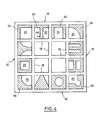
- Various embodiments of such tenon members 26 have been shown diagrammatically in FIG. 4.
- the tenon members intended to penetrate into the edge channels 20 of the bricks may for example be in the form of wedge-shaped protrusions which can affect various cross sections , as illustrated with reference 34, 36, 38, 40 in FIG. 4.
- the latter can be in the form of straight projections 42 intended to ensure close contact with the internal surface of the external walls 16 of the bricks. It is however essential to ensure good contact with the outer edge of the seal 10 coming into contact with these brick walls, and therefore it is necessary to extend these straight projections in a perpendicular direction, for example by at least one spacer 44 , ending in contact with the spacer wall 18 of the intermediate peripheral channels 22, which is opposite to the outer wall of the bricks.
- FIG. 4 represents eight particular embodiments of such a type of tenon members intended to penetrate into the intermediate peripheral channels 22 of the bricks. They can, for example, have very diverse shapes, for example T, U, E, A, or Ltel as illustrated in FIG. 4.
- the thickness of the plane peripheral frame 24 of the vertical joint according to the invention is chosen so as to be sufficient to produce a satisfactory thermal seal. In practice, such a thickness can be considerably reduced compared to the thickness of a traditional mortar joint, taking into account the good insulation properties of the expanded thermoplastic resins used.
- the tenon members 26 may be present over the entire periphery of the vertical seal 10, or else on only three sides or only on two opposite sides, as illustrated in Figure 1.
- the tenon members 26 are shaped so as to fit into the ends of the brick channels.
- Such shaping can be carried out beforehand, that is to say during molding, substantially to the dimension of said channels.
- the nature of the material will be chosen at a density high enough to ensure sufficient rigidity compatible with the ability to crush, however required for good sealing.
- the shaping can also be carried out at the same time of installation, by deformation of the material of the seal inside the channels which thus play in a way the matrix role.
- a softer material will of course be chosen, for example an expanded polystyrene of lower density.
- the outer edge of the joint ends in a flat surface.
- this plane peripheral edge could advantageously be replaced by a peripheral bead intended to form the seal between the two adjacent bricks, by compression between the external walls of said adjacent bricks.
- the peripheral bead affects a generally rectangular section of thickness equal to that of the planar frame.
- the peripheral bead has at least one region of thickness greater than that of the planar frame.
- This variant constitutes a preferred embodiment since it allows better compression of the peripheral bead and therefore better sealing.
- the peripheral bead will advantageously comprise two opposite lips projecting respectively from the two faces of the planar frame.
- the peripheral bead may affect a section in the general shape of a dovetail whose small base is attached to the outer edge of the plan frame and has a width equal to the thickness of the plan frame.
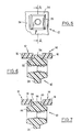
- the vertical joint 10 shown in Figure 1 is intended to be interposed between bricks 12 and 14 (see Figures 6 and 7) each comprising a plurality of horizontal channels resulting from the intersection of the four outer walls and the bracing walls bricks.
- the vertical joint 10 essentially comprises a planar peripheral frame 24 provided, on its two faces, with tenon members 26 which are shaped so as to be able to fit into the ends of the brick channels.
- the vertical seal is made of a semi-rigid expanded thermoplastic material, such as expanded polystyrene or expanded polyurethane, allowing a certain deformation of the tenon members 26 in contact with the external walls and bracing walls of the bricks.
- the outer edge of the seal 10 is extended by a peripheral sealing bead 54. This sealing bead, which is made in one piece with the planar peripheral frame supporting the tenon members, can be formed on two or three sides of the vertical joint.
- the peripheral bead 54 has a generally rectangular section of thickness equal to that of the planar frame 24 and a depth less than the thickness of the external walls 16 of the two bricks 12 and 14. Thus, during the positioning of the two bricks 12 and 14, the peripheral bead 54 will be compressed between the two adjacent external walls 16, without it may protrude from the external surface defined by the above-mentioned walls 16.
- this peripheral bead has at least one region of thickness greater than that of the planar frame.
- This bead comprises two opposite lips 58 and 60 projecting respectively from the two faces of the planar frame 24, so as to affect a section in the general shape of a dovetail .
- This dovetail section has the general shape of an isosceles trapezium whose small base is attached to the outer edge of the plan frame 24 and has a width equal to the thickness of the plan frame 24, and whose large base has a width greater than the thickness of the flat frame.
- the depth of the peripheral bead 56 that is to say the height of the abovementioned trapezium, is less than the thickness of the external walls 16 of the two bricks 12 and 14.
- the bead 56 When the two bricks 12 and 14 are brought together, the bead 56 will be compressed and therefore deformed outwards. However, because the depth of the bead is less than the thickness of the external walls 16, the excess material due to the deformation of the bead will not exceed the external surface of the bricks 12 and 14.
- FIGS. 6 and 7 the bricks 12 and 14 have been shown at a distance from the peripheral seal, but it is understood that, in the normal position of use, the beads 54 and 56 are compressed by the two adjacent bricks.
- the vertical seal 10 has a recess or passage 62 on only one of the sides of the peripheral frame.
- This recess 62 formed in the lower part of the peripheral frame 24, is intended to prevent the interruption of the horizontal cement joint.
- Such a particular arrangement makes it possible to considerably increase the mechanical resistance of the assembly.
- peripheral frame 24 only the vertical parts of the peripheral frame 24 have a peripheral bead 56, while the upper part of this peripheral frame will be flat.
Landscapes
- Engineering & Computer Science (AREA)
- Architecture (AREA)
- Physics & Mathematics (AREA)
- Electromagnetism (AREA)
- Civil Engineering (AREA)
- Structural Engineering (AREA)
- Building Environments (AREA)
Claims (14)
Priority Applications (1)
| Application Number | Priority Date | Filing Date | Title |
|---|---|---|---|
| AT83400070T ATE21719T1 (de) | 1982-05-28 | 1983-01-12 | Senkrechte fuge fuer hohlbloecke. |
Applications Claiming Priority (6)
| Application Number | Priority Date | Filing Date | Title |
|---|---|---|---|
| FR8209326A FR2527670A1 (fr) | 1982-05-28 | 1982-05-28 | Joints verticaux de briques prefabriques |
| FR8209326 | 1982-05-28 | ||
| FR8210859 | 1982-06-22 | ||
| FR8210859A FR2528888A1 (fr) | 1982-06-22 | 1982-06-22 | Joint vertical de briques creuses |
| FR8215580 | 1982-09-15 | ||
| FR8215580A FR2532974A2 (fr) | 1982-09-15 | 1982-09-15 | Joint vertical de briques creuses |
Publications (3)
| Publication Number | Publication Date |
|---|---|
| EP0095949A2 EP0095949A2 (de) | 1983-12-07 |
| EP0095949A3 EP0095949A3 (en) | 1984-07-11 |
| EP0095949B1 true EP0095949B1 (de) | 1986-08-27 |
Family
ID=27251111
Family Applications (1)
| Application Number | Title | Priority Date | Filing Date |
|---|---|---|---|
| EP19830400070 Expired EP0095949B1 (de) | 1982-05-28 | 1983-01-12 | Senkrechte Fuge für Hohlblöcke |
Country Status (4)
| Country | Link |
|---|---|
| EP (1) | EP0095949B1 (de) |
| DE (1) | DE3365489D1 (de) |
| ES (1) | ES277369Y (de) |
| PT (1) | PT76086A (de) |
Family Cites Families (4)
| Publication number | Priority date | Publication date | Assignee | Title |
|---|---|---|---|---|
| US2392552A (en) * | 1943-05-10 | 1946-01-08 | Albert Kahn | Hollow building block |
| AU411757B2 (en) * | 1968-03-12 | 1971-03-29 | James Whitson Hubert | Mortarless brick and wall construction |
| FR2260671A1 (en) * | 1974-02-12 | 1975-09-05 | Bourcart Emile | Heat-distributing section for building-walls - consists of tubular, sleeve for circulating hot air |
| DE3021131A1 (de) * | 1980-06-04 | 1981-12-10 | Heinrich Wilhelm 6300 Gießen Schneider | Aus bausteinen zusammengesetzte mauerkonstruktion |
-
1983
- 1983-01-12 DE DE8383400070T patent/DE3365489D1/de not_active Expired
- 1983-01-12 PT PT7608683A patent/PT76086A/pt unknown
- 1983-01-12 EP EP19830400070 patent/EP0095949B1/de not_active Expired
- 1983-01-12 ES ES1983277369U patent/ES277369Y/es not_active Expired
Also Published As
| Publication number | Publication date |
|---|---|
| EP0095949A2 (de) | 1983-12-07 |
| ES277369U (es) | 1985-02-16 |
| PT76086A (fr) | 1983-02-01 |
| DE3365489D1 (en) | 1986-10-02 |
| ES277369Y (es) | 1985-09-01 |
| EP0095949A3 (en) | 1984-07-11 |
Similar Documents
| Publication | Publication Date | Title |
|---|---|---|
| EP0354149B1 (de) | Verfahren und Vorrichtung zum dichten Verbinden von Beregnung ausgesetzten Platten | |
| EP0095949B1 (de) | Senkrechte Fuge für Hohlblöcke | |
| FR2567177A1 (fr) | Perfectionnement aux elements de construction a emboitement d'un bloc et d'une plaque d'isolation. | |
| EP0090708A1 (de) | Lager für Bodenbelagsplatten | |
| EP1060312A1 (de) | Modulares schalungselement für gebäudewände | |
| FR2642109A1 (fr) | Structure creuse allongee et son procede de fabrication | |
| FR2813624A1 (fr) | Profile de raccord et d'etancheite, dispositif de raccord, panneau a structure sandwich, et ensemble de facade, de cloison ou de couverture | |
| EP0307291A1 (de) | Brückenkopf zur Querpassage eines Grabens | |
| FR2528888A1 (fr) | Joint vertical de briques creuses | |
| FR2660952A1 (fr) | Elements prefabriques pour la realisation d'une dalle et dalle obtenue a partir de ces elements. | |
| FR2459333A1 (fr) | Element de construction prefabrique et son procede de fabrication | |
| FR2941725A1 (fr) | Element d'isolation thermique pour bloc prefabrique et bloc de construction ainsi obtenu. | |
| EP1060311B1 (de) | Modulares element für wände oder doppelwände für trockenmontage | |
| FR2912437A1 (fr) | Planelle isolante pour batiment. | |
| EP1447491B1 (de) | Satz von Glasbausteinen | |
| FR2683242A1 (fr) | Dalle modulaire pour cloison horizontale. | |
| EP0103494A2 (de) | Stossfuge für Bausteine | |
| FR2653800A1 (fr) | Petits composants nouveaux de construction. | |
| FR3044690A1 (fr) | Bloc de beton moule avec entretoise en forme de chevron | |
| FR2977265A1 (fr) | Panneau composite pour l'isolation thermique de facade de batiments | |
| FR2546210A1 (fr) | Bloc de construction equipe de joint d'etancheite vertical et son procede de fabrication | |
| EP3957794B1 (de) | Selbstblockierender betonpflasterstein | |
| EP0334699A1 (de) | Verkleidungsstein mit Verbund, insbesondere zum Schützen von Böschungen | |
| FR2532974A2 (fr) | Joint vertical de briques creuses | |
| FR2524520A1 (fr) | Pierre de construction et couche thermiquement isolante pour cette pierre de construction |
Legal Events
| Date | Code | Title | Description |
|---|---|---|---|
| PUAI | Public reference made under article 153(3) epc to a published international application that has entered the european phase |
Free format text: ORIGINAL CODE: 0009012 |
|
| AK | Designated contracting states |
Designated state(s): AT BE CH DE FR GB IT LI LU NL SE |
|
| PUAL | Search report despatched |
Free format text: ORIGINAL CODE: 0009013 |
|
| AK | Designated contracting states |
Designated state(s): AT BE CH DE FR GB IT LI LU NL SE |
|
| 17P | Request for examination filed |
Effective date: 19850107 |
|
| GRAA | (expected) grant |
Free format text: ORIGINAL CODE: 0009210 |
|
| AK | Designated contracting states |
Kind code of ref document: B1 Designated state(s): AT BE CH DE FR GB IT LI LU NL SE |
|
| PG25 | Lapsed in a contracting state [announced via postgrant information from national office to epo] |
Ref country code: NL Effective date: 19860827 Ref country code: IT Free format text: LAPSE BECAUSE OF FAILURE TO SUBMIT A TRANSLATION OF THE DESCRIPTION OR TO PAY THE FEE WITHIN THE PRESCRIBED TIME-LIMIT;WARNING: LAPSES OF ITALIAN PATENTS WITH EFFECTIVE DATE BEFORE 2007 MAY HAVE OCCURRED AT ANY TIME BEFORE 2007. THE CORRECT EFFECTIVE DATE MAY BE DIFFERENT FROM THE ONE RECORDED. Effective date: 19860827 Ref country code: AT Effective date: 19860827 |
|
| REF | Corresponds to: |
Ref document number: 21719 Country of ref document: AT Date of ref document: 19860915 Kind code of ref document: T |
|
| PG25 | Lapsed in a contracting state [announced via postgrant information from national office to epo] |
Ref country code: SE Effective date: 19860831 |
|
| REF | Corresponds to: |
Ref document number: 3365489 Country of ref document: DE Date of ref document: 19861002 |
|
| PG25 | Lapsed in a contracting state [announced via postgrant information from national office to epo] |
Ref country code: LU Free format text: LAPSE BECAUSE OF NON-PAYMENT OF DUE FEES Effective date: 19870131 Ref country code: LI Effective date: 19870131 Ref country code: CH Effective date: 19870131 |
|
| NLV1 | Nl: lapsed or annulled due to failure to fulfill the requirements of art. 29p and 29m of the patents act | ||
| PLBE | No opposition filed within time limit |
Free format text: ORIGINAL CODE: 0009261 |
|
| STAA | Information on the status of an ep patent application or granted ep patent |
Free format text: STATUS: NO OPPOSITION FILED WITHIN TIME LIMIT |
|
| BERE | Be: lapsed |
Owner name: LAITRAM SARL Effective date: 19870131 |
|
| 26N | No opposition filed | ||
| PG25 | Lapsed in a contracting state [announced via postgrant information from national office to epo] |
Ref country code: FR Free format text: LAPSE BECAUSE OF NON-PAYMENT OF DUE FEES Effective date: 19870930 |
|
| REG | Reference to a national code |
Ref country code: CH Ref legal event code: PL |
|
| PG25 | Lapsed in a contracting state [announced via postgrant information from national office to epo] |
Ref country code: DE Effective date: 19871001 |
|
| REG | Reference to a national code |
Ref country code: FR Ref legal event code: ST |
|
| PG25 | Lapsed in a contracting state [announced via postgrant information from national office to epo] |
Ref country code: GB Free format text: LAPSE BECAUSE OF NON-PAYMENT OF DUE FEES Effective date: 19881122 |
|
| PG25 | Lapsed in a contracting state [announced via postgrant information from national office to epo] |
Ref country code: BE Effective date: 19890131 |