EP0095891B2 - Dispositif pour transformer un mouvement rotatif dans un mouvement linéaire - Google Patents
Dispositif pour transformer un mouvement rotatif dans un mouvement linéaire Download PDFInfo
- Publication number
- EP0095891B2 EP0095891B2 EP83303019A EP83303019A EP0095891B2 EP 0095891 B2 EP0095891 B2 EP 0095891B2 EP 83303019 A EP83303019 A EP 83303019A EP 83303019 A EP83303019 A EP 83303019A EP 0095891 B2 EP0095891 B2 EP 0095891B2
- Authority
- EP
- European Patent Office
- Prior art keywords
- raceway
- balls
- ring
- shaft
- components
- Prior art date
- Legal status (The legal status is an assumption and is not a legal conclusion. Google has not performed a legal analysis and makes no representation as to the accuracy of the status listed.)
- Expired
Links
Images


Classifications
-
- F—MECHANICAL ENGINEERING; LIGHTING; HEATING; WEAPONS; BLASTING
- F16—ENGINEERING ELEMENTS AND UNITS; GENERAL MEASURES FOR PRODUCING AND MAINTAINING EFFECTIVE FUNCTIONING OF MACHINES OR INSTALLATIONS; THERMAL INSULATION IN GENERAL
- F16H—GEARING
- F16H19/00—Gearings comprising essentially only toothed gears or friction members and not capable of conveying indefinitely-continuing rotary motion
- F16H19/02—Gearings comprising essentially only toothed gears or friction members and not capable of conveying indefinitely-continuing rotary motion for interconverting rotary or oscillating motion and reciprocating motion
- F16H19/025—Gearings comprising essentially only toothed gears or friction members and not capable of conveying indefinitely-continuing rotary motion for interconverting rotary or oscillating motion and reciprocating motion comprising a friction shaft
-
- Y—GENERAL TAGGING OF NEW TECHNOLOGICAL DEVELOPMENTS; GENERAL TAGGING OF CROSS-SECTIONAL TECHNOLOGIES SPANNING OVER SEVERAL SECTIONS OF THE IPC; TECHNICAL SUBJECTS COVERED BY FORMER USPC CROSS-REFERENCE ART COLLECTIONS [XRACs] AND DIGESTS
- Y10—TECHNICAL SUBJECTS COVERED BY FORMER USPC
- Y10T—TECHNICAL SUBJECTS COVERED BY FORMER US CLASSIFICATION
- Y10T74/00—Machine element or mechanism
- Y10T74/18—Mechanical movements
- Y10T74/18568—Reciprocating or oscillating to or from alternating rotary
- Y10T74/18576—Reciprocating or oscillating to or from alternating rotary including screw and nut
-
- Y—GENERAL TAGGING OF NEW TECHNOLOGICAL DEVELOPMENTS; GENERAL TAGGING OF CROSS-SECTIONAL TECHNOLOGIES SPANNING OVER SEVERAL SECTIONS OF THE IPC; TECHNICAL SUBJECTS COVERED BY FORMER USPC CROSS-REFERENCE ART COLLECTIONS [XRACs] AND DIGESTS
- Y10—TECHNICAL SUBJECTS COVERED BY FORMER USPC
- Y10T—TECHNICAL SUBJECTS COVERED BY FORMER US CLASSIFICATION
- Y10T74/00—Machine element or mechanism
- Y10T74/19—Gearing
- Y10T74/19181—Gearing toothed gear and recirculated unconnected elements
Definitions
- the present invention relates to devices for converting rotary movement into linear movement.
- Such devices are well known per se and a simple example of a known device is a screw- threaded spindle mating with a nut runner embodied as a wheel or knob for example.
- This simple device has a high frictional coefficient between the components which is disadvantageous in many applications.
- Recirculating balls can be incorporated in the threads to provide a ball-screw race with improved characteristics.
- Ball-screw mechanisms of this type function well but are costly to manufacture.
- a general object of the present invention is to provide an improved device for converting rotary movement into linear movement.
- US-A-2 350 538 describes devices for converting rotary motion into linear motion. These known devices employ balls engaging in a multi-turn helical groove in a surface of one component and with a plain surface of another component which confronts the grooved surface. Axial force is used to cause the balls to wedge with the groove.
- US-A-4 034 833 describes further devices having, in common with the present invention, first and second components rotatable about a common axis, the components having confronting surfaces one of said confronting surfaces being substantially plain while the other of said confronting surfaces is provided with a groove forming a raceway or a track of part helical form, rolling elements in the form of balls between the confronting surfaces of the components in mutual contact with the surfaces and the raceway which defines a ball contact angle in the range of 3° to 30° and additional relief of said other confronting surface to permit the transfer of the balls from the end to the start of the raceway, the balls being guided for progressive continuous rolling movement along the raceway and pre-loaded throughout their movement along the raceway in a manner such that direct relative linear motion between the components parallel to the common axis is resisted in a least one direction while relative combined rotary and linear movements can occur in response to rotary drive imparted to one of the components.
- an additional component or additional components define guide means which serves to assist in the transfer of the balls and the space between the confronting surfaces is smaller than the diameter of the balls in order to inherently subject the balls to direct radial pre-load.
- the relief in the other confronting surface may be a slot or channel.
- the guide means can contact the rolling elements in the manner of cams to guide or assist in their transfer through the relief from the end to the start of the raceway. It is desirable to have some means to locate with the components and maintain their mutual alignment to ensure the confronting surfaces are substantially parallel.
- one of the components is a ring and the other is a shaft passing through the ring.
- additional outrigger bearings receive the shaft to hold the latter in the correct orientation with respect to the ring and resist tilting forces.
- Such outrigger bearings can be shaped to retain the balls in the raceway.
- the component in the form of a ring may have the grooved raceway on its inner periphery while the other component may take the form of a plain shaft, tube or spindle.
- the rolling elements have an epicyclic relationship with the driven component of the device.
- the component which has the raceway may have several independent raceways each containing a set of balls or several components, each with its raceway containing balls, may be combined with a common component with the plain confronting surface.
- the groove which forms the raceway containing the rolling elements is preferably V-shaped or of curvilinear profile.
- the raceway effectively constitutes an interrupted single screw-thread with start and end regions spaced apart along the common axis of rotation to provide the lead.
- the shape of the groove in combination with the radial pre-loading creates a wedging effect with the balls to resist direct linear motion between the components.
- the groove can have a differential contact angle in relation to the lead and a coarse lead would generally have a smaller contact angle.
- the groove may have a symmetrical or asymmetrical profile, say to allow slippage or relative linear motion in one direction only.
- the balls of the set may contact one another thus to keystone the elements and prevent them falling out of the device during assembly or disassembly. This arrangement is particularly applicable where raceway has a fine lead.
- a cage can however be used to space the elements.
- end covers detachable or non- detachable, protect the raceway and rolling elements. Such end covers also retain the rolling elements in the raceway and may provide guide pieces serving to guide the transferrence of the elements.
- the main components of the device would be made from metal but in certain applications synthetic plastic can be used.
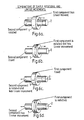
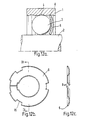
- a device constructed in accordance with the invention includes a first or outer component in the form of a ring 1 and a second or inner component in the form of a shaft, tube or spindle.
- the ring 1 and the shaft 2 mutually contact rolling elements in the form of balls 3.
- the ring 1 has a track or raceway 4 formed at its inner periphery to guide the balls 3 for progressive rolling motion.
- the ring 1 has recesses 8 in its side faces for receiving annular cover plates 6.
- the track 4 in this embodiment takes the form of a symmetrical part-helical V-shaped groove.
- the balls 3 contact the track 4 to permit direct relative rotation between the components 1, 2 while inhibiting direct axial or linear motion.
- the balls 3 are guided for continuous movement in succession around the longitudinal axis of the shaft 2.
- a transverse slot 7 in the ring 1 and guide pieces 9 on the covers 6 collectively serve to guide the balls 3 from the end to the start of the track 4.
- the balls 3 make wedging contact with flanks or faces of the track 4 and the shaft 2 thereby to resist direct relative linear movement parallel to the longitudinal axis of the shaft 2.
- Rotary motion between the components 1,2 causes such linear movement via the balls 3 and the track 4 so that the device can function to convert rotary motion into linear motion.
- the balls 3 can be placed in the track 4 and the covers 6 fitted.
- the outer ring 1 with only one cover 6 fitted can be placed over the shaft 2 and the balls 3 fed into the track 4 through the slot 7. The other cover 6 is then fitted.
- covers 6 is not essential for retaining the balls 3 and the balls 3 can be retained in the track 4 in other ways, e.g. by a keystone effect or by using a cage.
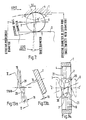
- Figures 5a to 5b depict, by way of further examples, various shapes for the track 4.
- the reference numeral 5 is used to denote the effective contact angles with respect to the balls 3 as defined by the track 4 or parts thereof.
- the reference numeral 5' denotes the total included angle of the track 4.
- Figures 5a and 5b illustrate, respectively, tracks 4 with symmetrical and asymmetrical profiles with flat faces
- Figures 5c and 5d illustrate, respectively, tracks 4 with symmetrical and asymmetrical profiles with curvilinear faces.
- Figures 5b and 5b which depict tracks 4 with asymmetrical profiles, and different contact angles 5, permit direct relative linear motion in one direction while inhibiting such motion in the opposite direction.
- Figures 5a and 5c which show tracks 4 with symmetrical profiles and relatively small uniform contact angles 5, ensure high operative traction forces between the components 1, 2 and the balls 3.
- relative linear motion is inhibited in both directions.
- Rotary motion will, however, cause controlled linear motion but if this linear motion is resisted by a relatively high external force, slippage will occur without restricting the rotary motion and damaging the components.
- Figures 6a to 6d depict various ways in which a device constructed in accordance with the invention can be employed to provide relative motion between the components 1, 2.
- the components 1, 2 of the device which move relatively can take a variety of shapes and sizes.
- the inner component can be hollow and of any length and a single inner component may have a plurality of outer components mounted thereon.
- the conversion of rotary motion to linear motion by the devices constructed in accordance with the invention is not the same as a screw and nut with mating threads. The latter move linearly in equal ratio to each other according to the pitch of the thread. Also the devices constructed in accordance with the invention operate in a different manner to a conventional ball-screw arrangement in which the recirculating balls make four point contact with the threads on the shaft and in the nut. Devices in accordance with the invention have only a partially threaded member in that the raceway groove or track 4 is of part helical form i.e. less than 360° angle of helix.
- the rotary movements of the shaft 2, the set of balls 3 and the outer ring 2 have an epicyclic relationship.
- the resultant linear movement of the outer ring 1 or the shaft 2 (termed the pitch) is dependent on the rotation of the set of balls 3 in the track 4.
- the magnitude of the pitch is not the same as the lead of the track 4 because of the epicyclic effects.
- the net rotation of the outer ring 1 and the ball set which causes linear movement can be calculated from the following expression: where N R - net rotation of the ring 1 and of the ball set and R R - Revolutions of the outer ring 1.
- N R - net rotation of the ring 1 and of the ball set and R R - Revolutions of the outer ring 1.
- the expression 3 becomes NR - 1 - D2/(D1 + D2) and on further simplification NR - D1/(D1 + D2) which is the same as expression 2).
- the linear movement LM of the outer ring 1 or shaft 2 an be calculated from:
- the parameter D1 i.e. the diameter of the outer ring raceway should actually take account of the contact angle 5 between the raceway 4 and the balls 3 and also the fact that under axial load the balls 3 will not necessarily rotate about an axis that is parallel to the shaft 2 and outer ring 1 axes.
- the following expression can be used: where PCD - the effective pitch circle diameter of the ball set and DB - the effective ball diameter.
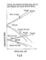
- a characteristic of the relationships displayed in Figure 8 is that a faster linear speed is provided with a device in which the load is active in the same direction. This is especially useful when the device is to be employed in a mechanism where a quicker response - such as a quick return - is desirable.
- Computer program models that combine load distribution, and Hertzian contact stress theory with traction, spin and lubrication film theory, can predict for a given design the ratios of linear to rotary movement for the shaft or outer ring under applied load, speed and lubrication cinditions.
- a device can thus be designed to give a specific performance within the practical limits of the helical raceway lead and the load/speed capabilities.
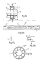
- the inner component 2 may have several outer components 1 each with its own set of balls 3 guided in a track 4 mounted thereon.
- the axial-load carrying capacity of the device can be increased since if one ring 1 can take a load of 25 kg then the load which can be taken by say, five rings 1 in tandem would be nominally 125 kg, subject to certain conditions.
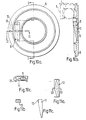
- Figure 9 depicts a device wherein a single outer ring 1 has sets of balls 3 in the separate tracks 4.
- four covers 6 are used. These covers 6 are flexible and resilient to deform inwardly for location purposes.
- a shaped peripheral flange 10 is provided for this purpose. Two of the covers 6 are disposed centrally of the ring 1 in abutting relationship in a common widened recess 8'.
- FIGS 10 and Figures 11 depict a cover 6 and guide piece 9 suitable for use with devices constructed in accordance with the invention.
- the cover 6 can be made from synthetic plastics or metal, machined, cast, sintered or moulded.
- a recess 11 serves to receive the ball guide piece 9 provided with a ball-contacting working face 12 which can be flat or grooved.
- the guide piece 9 is best made from a wear resilient material such as bronze or hardened steel or plastics such as a phenolic resin; polyamide or PTFE.
- the covers 6 for a device may be identical since one cover 6 is merely inverted in relation to the other to arrange the faces 12 in parallel opposition.
- the guide piece 9 may be simply press-fitted in the recess 11 and a hole 13 in the cover 6 can permit a small rod to be used to remove the guide piece 9.
- the guide piece 9 can be inserted in the recess 11 either way up to suit tracks 4 of opposite hand with the same lead and lead angles.
- the covers 6 may have location means in the form of pins 33 for engaging in recesses or depressions in the ring 1 or some structure associated therewith.
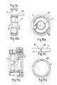
- Figure 12a shows a device wherein the outer ring 1 has two helical V-shaped recesses 8 for receiving the end covers 6. These recesses 8 can have the same depth and lead as the track or raceway 4.
- the covers 6 are again resilient and conveniently made from spring steel, hardened and tempered steel strip, phosphor bronze or beryllium copper.
- the covers 6 can be split as shown in Figures 12b and 12c to deform and wind into the recesses 8.
- the covers 6 tend to locate around the balls 3 to retain the balls 3 in the track 4.
- Notches 15 are provided around the outer periphery of the cover 6 to enable a tool to fit the cover 6 to the ring 1 and adjust the cover 6 circumferentially.
- integral lugs forming the guide pieces 9 are incorporated on the covers 6 and the width between the guide pieces 9 may be adjusted by rotating either or both covers 6 with the aid of the tool.
- Figures 13 depicts an additional or supplementary guide means for guiding the balls 3 between the start 17 and end 18 of the raceway or track 4 in the outer ring 1.
- This guide means takes the form of a machined channel 16 in the ring 1 directly connecting the regions 17,18 of the track 4.
- the channel 16 relieves the contact path 19 of the opposite sides of the track 4 as at 20 to bring the balls 3 gradually out of and into the load zones at the end regions 17,18 of the track 4.
- transverse slot 7 is provide in the ring at an angle to the axis Z-Z.
- the intersection of the raceway 4 with the inclined slot 7 again relieves the ball contact path 19 on opposite sides of the track 4 as at 20.
- the guide pieces 9 shown in dotted outline
- This provides a gradual lift from the slot 7 into the raceway 4.
- Figure 15a depicts a device wherein the ring 1 seats on a pair or outrigger plain bearings 22 which receive the shaft 2 (not shown). These bearing 22 have opposed portions 23 which retain the balls 3 in the track 4.
- a housing 25 which may be a single or multi-part unit surrounds the ring 1 and, if necessary, encapsulates the structure.
- the covers 6 are fitted to the housing 25 to overlap the ring 1.
- the ring 1 has notches in its side faces which receive the pins 33 on the covers 6 to locate the latter.
- the device preferably has means 26 which permits the ring 4 to be locked against rotation or drivably rotated. Such means can take the form of a simple mounting flange or keyway or a gear or pulley provided on the housing 25 or otherwise.
- Figure 15b shows, as an example, a simple notch serving as the aforesaid locking means 26.
- Figure 16 depicts a device essentially as in Figures 15 but employing a drawn cup 24 as a housing.
- the shaft 2 is also shown located within the ring 1.
- a flange 14 on the housing 24 serves to mount the device to a static or drivable member.
- Figures 17a to 17d depict one way of fabricating the ring 1 particularly where an external housing (24, 25 as in Figures 15 and 16), is used.
- a metal strip 27 is treated by pressing or rolling to produce the raceway or track 4.
- the slot 7 is also pressed or rolled into the strip 27 at the end of the track 4.
- the strip 27 is then rolled into circular form and fitted into the associated housing 24, 25.
- the ends of the strip 27 can be joined together as by welding.
- the ends of the strip 27 can be angled-off and a small gap left between the ends when the strip 27 is shaped to form the ring 1. This gap can be designed to assist the transfer of the balls 3 from the end to the start of the track 4.
- Figures 18a to 18c depict a device which also uses a metal strip 27 as the ring 1.
- the slot 7 and guide pieces 9 are provided by a supportive housing 28 as by moulding or machining.
- the strip 27 which is preferably resilient can be sprung into the housing 28 and located both axially and radially thereby.
- the housing 24 could be of multi-part construction however so that the strip 27 can be hardened and then placed inside the parts of the housing 28. In such an arrangement, the housing parts can be united by ultrasonic welding, for example, to entrap the ring 1.
- FIG. 19a - 19c Another method of fabricating the ring 1 is shown in Figures 19a - 19c.
- the ring 1 has a fracture 29 and to obtain a straight fracture the side faces of the ring 1 are initially provided with notches 32.
- the ring 1 is then placed into a jig 31 which serves to twist the ring 1 within its elastic limit to provide a helical form 30 with the desired lead to permit the creation of the track 4 thereafter by circumferential grinding.
- the ring 1 When the ring 1 is removed it reverts to its normal form to cause the track 4 to assume its helical shape.
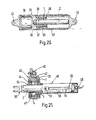
- Figure 20 depicts a mechanism which can incorporate any of the devices described e.g. single row, single rows mounted in tandem or a double a double row device.
- a double-row device designated 39 is employed.
- an electric motor 34 is mounted in a tubular housing 35 and drives the shaft 2 of the device 39 via a simple coupling 36.
- the shaft 2 is supported and located by a rolling bearing or plain flanged bush bearing 37 which may be received in an intermediate housing 38 fixed to the tubular housing 35.
- the ring 1 of the device 39 moves linearly along the shaft 2 as the shaft rotates.
- the device 39 is conveniently mounted in an intermediate support housing 40 fixed to a second tubular housing 41.
- the housing 41 is received in telescopic manner in the housing 35 and, e.g.
- the motor 34 operates to move the inner housing 41 in and out of the outer housing 35.
- coupling means 42 such as apertured lugs, which permit the mechanism to be connected, respectively, to some appliance(s) to be actuated by the mechanism and mounted to a fixed abutment or pivot joint.
- Figure 21 shows an actuator mechanism incorporating a device as described but driven by an external source.
- the outer ring 1 of the device is mounted in as support housing 25 having gear teeth 43 (spur, helical or worm) on its exterior.
- the assembly composed of the outer ring 1 and the housing 25 is mounted in an eccentric split housing 45.
- the ring and housing assembly 1, 25 is axially located by ball or needle thrust bearings, or thrust pads 44.
- Flange or lugs 46 permit the housing 45 and hence the mechanism to be secured to the frame of a machine for example.
- An opening 47 in the housing 45 permits access to the gear teeth 43 and enables the ring 1 to be driven rotatably from the external source by an idler gear or directly.
- the shaft 2 extends through the housing 45 and extends within a tube 48 closed at one end remote from the device 1.
- Bearings 54 guide the shaft 2 for linear movement.
- the bearings 54 preferably also seal the Interior of the housing 45 and can take the form of plain bushes or linear ball bushings.
- the tube 48 is fixed to one section of the housing 45 and carries a sensor 49 at its closed end for detecting the presence of the shaft 2.
- a longitudinal slot in the tube 48 receives a further sensor 52 which can be adjusted along the slot and clamped in a desired location according to the extent of intended linear travel of the shaft 2.
- Indicia 51 forming a scale are provided on the tube 48 alongside the slot.
- a pin 53 mounted to the shaft 2 serves to actuate the displaceable sensor 52 and prevents relative rotation between the shaft 2 and the tube 48.
- the sensors 49, 52 would be connected to a suitable control circuit designed to reverse the direction of rotation of the ring 1.
- a coupling 55 is fitted to the end of the shaft 2 remote from the tube 48. This coupling 55 permits appliance(s) such as levers or the like to be actuated by the linear motion of the shaft 2.
- the shaft 2 can be made to reciprocate by a predetermined stroke.
- a number of mechanisms of the type illustrated can be driven by one common motor or power source.
- a drive motor can conveniently drive the or each mechanism via a worm and worm wheel gear train. Gearing providing a reduction or increased speed ratios can also be incorporated.
- the sensores 49, 52 can be replaced by other forms of transducers to provide accurate motion and indexing to intermediate stations of the mechanism.
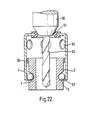
- Figure 22 depicts a device constructed in accordance with the invention and used to control the rate of feed of a twist drill 63 and limit the depth of hole cut thereby.
- the track 4 is provided on an inner sleeve 2 while the outer component 1 is a plain tube.
- the outer tube 1 locates to the drill chuck 60 via a grommet 61 designed to impart rotation to the tube 1.
- the tube 1 has an inturned lip 62 at its opposite end to retain the sleeve 2.
- a ring 64 is provided on the exterior of the inner sleeve 2. This ring 64 performs various functions: It prevents swarf or foreign matter from entering the track 4; it maintains the relative orientation between the components 1, 2 thereby acting as a guide and it acts as an end stop between the components 1, 2.
- the sleeve is held stationary so that the rotating tube 1 and drill chuck 60 move linearly downwardly over the inner sleeve 2 by a predetermined amount. Holes 65 in the tube 1 allow swarf to escape.
Claims (15)
Applications Claiming Priority (2)
| Application Number | Priority Date | Filing Date | Title |
|---|---|---|---|
| GB8215676 | 1982-05-28 | ||
| GB8215676 | 1982-05-28 |
Publications (3)
| Publication Number | Publication Date |
|---|---|
| EP0095891A1 EP0095891A1 (fr) | 1983-12-07 |
| EP0095891B1 EP0095891B1 (fr) | 1986-07-30 |
| EP0095891B2 true EP0095891B2 (fr) | 1988-11-02 |
Family
ID=10530706
Family Applications (1)
| Application Number | Title | Priority Date | Filing Date |
|---|---|---|---|
| EP83303019A Expired EP0095891B2 (fr) | 1982-05-28 | 1983-05-25 | Dispositif pour transformer un mouvement rotatif dans un mouvement linéaire |
Country Status (4)
| Country | Link |
|---|---|
| US (1) | US4718291A (fr) |
| EP (1) | EP0095891B2 (fr) |
| DE (1) | DE3364922D1 (fr) |
| GB (1) | GB2121507B (fr) |
Families Citing this family (49)
| Publication number | Priority date | Publication date | Assignee | Title |
|---|---|---|---|---|
| GB2165916B (en) * | 1984-10-11 | 1988-07-20 | Rhp Group Plc | Improvements in devices for coverting rotary movement into linear movement |
| GB2171169B (en) * | 1985-02-14 | 1988-08-24 | Rhp Group Plc | Improvements in devices for converting rotary movement into linear movement |
| US5022277A (en) * | 1989-08-22 | 1991-06-11 | Consolier Industries, Inc. | Screw and nut machine |
| US5491633A (en) * | 1991-05-20 | 1996-02-13 | General Motors Corporation | Position sensor for electromechanical suspension |
| CH697259B1 (fr) * | 1997-03-18 | 2008-07-31 | Roger Bajulaz | Mécanisme desmodromique à cames. |
| NL1006944C2 (nl) | 1997-09-04 | 1999-03-11 | Mark Hans Emanuel | Chirurgische endoscopische snij-inrichting. |
| DE19752696C1 (de) * | 1997-11-28 | 1999-05-12 | Deutsch Zentr Luft & Raumfahrt | Linearantrieb |
| DE29816884U1 (de) * | 1998-09-21 | 1998-12-03 | Dewert Antriebs Systemtech | Elektromotorischer Linearantrieb |
| US7226459B2 (en) | 2001-10-26 | 2007-06-05 | Smith & Nephew, Inc. | Reciprocating rotary arthroscopic surgical instrument |
| US6813969B2 (en) | 2002-07-01 | 2004-11-09 | Delphi Technologies, Inc. | Rocker return liner for ball nut |
| EP1722951B1 (fr) * | 2004-03-12 | 2020-04-22 | Pregis Intellipack LLC | Distributeur manuel |
| US8062214B2 (en) | 2004-08-27 | 2011-11-22 | Smith & Nephew, Inc. | Tissue resecting system |
| KR100986127B1 (ko) * | 2005-06-20 | 2010-10-07 | 이관호 | 볼쐐기식 감속기 |
| US7900710B2 (en) * | 2007-11-09 | 2011-03-08 | Hansen Michael B | Power cup cutter |
| US9155454B2 (en) | 2010-09-28 | 2015-10-13 | Smith & Nephew, Inc. | Hysteroscopic system |
| DK177504B1 (da) | 2010-10-12 | 2013-08-12 | Liniax Aps | Friktionsdrivmekanisme |
| EP2949967B1 (fr) * | 2014-05-29 | 2020-05-06 | Fundacja Rozwoju Kardiochirurgii Im. Prof. Zbigniewa Religi | Mécanisme pour un mouvement linéaire alternatif pour un dispositif médical |
| US9976350B2 (en) | 2014-10-17 | 2018-05-22 | Ashmin Holding Llc | Up drill apparatus and method |
| US10017994B2 (en) * | 2014-10-17 | 2018-07-10 | Ashmin Holding Llc | Boring apparatus and method |
| EP3232955A1 (fr) | 2014-12-16 | 2017-10-25 | Covidien LP | Dispositif chirurgical avec système d'extraction tissulaire incorporé |
| US10772652B2 (en) | 2015-01-28 | 2020-09-15 | Covidien Lp | Tissue resection system |
| US10750931B2 (en) | 2015-05-26 | 2020-08-25 | Covidien Lp | Systems and methods for generating a fluid bearing for an operative procedure |
| WO2016205359A2 (fr) | 2015-06-17 | 2016-12-22 | Smith & Nephew, Inc. | Instrument chirurgical à refroidissement à changement de phase |
| WO2016205126A1 (fr) | 2015-06-17 | 2016-12-22 | Covidien Lp | Dispositif endoscopique avec bride de goutte-à-goutte et procédés d'utilisation pour une procédure de fonctionnement |
| CA2989162A1 (fr) | 2015-06-18 | 2016-12-22 | Covidien Lp | Instrument chirurgical avec commande d'aspiration |
| US11864735B2 (en) | 2016-05-26 | 2024-01-09 | Covidien Lp | Continuous flow endoscope |
| US10299819B2 (en) | 2016-07-28 | 2019-05-28 | Covidien Lp | Reciprocating rotary surgical cutting device and system for tissue resecting, and method for its use |
| US10299803B2 (en) | 2016-08-04 | 2019-05-28 | Covidien Lp | Self-aligning drive coupler |
| US10772654B2 (en) | 2017-03-02 | 2020-09-15 | Covidien Lp | Fluid-driven tissue resecting instruments, systems, and methods |
| US10869684B2 (en) | 2018-02-13 | 2020-12-22 | Covidien Lp | Powered tissue resecting device |
| US11547815B2 (en) | 2018-05-30 | 2023-01-10 | Covidien Lp | Systems and methods for measuring and controlling pressure within an internal body cavity |
| US11065147B2 (en) | 2018-10-18 | 2021-07-20 | Covidien Lp | Devices, systems, and methods for pre-heating fluid to be introduced into a patient during a surgical procedure |
| US11197710B2 (en) | 2018-10-26 | 2021-12-14 | Covidien Lp | Tissue resecting device including a blade lock and release mechanism |
| US11083481B2 (en) | 2019-02-22 | 2021-08-10 | Covidien Lp | Tissue resecting instrument including an outflow control seal |
| US11154318B2 (en) | 2019-02-22 | 2021-10-26 | Covidien Lp | Tissue resecting instrument including an outflow control seal |
| US10898218B2 (en) | 2019-02-25 | 2021-01-26 | Covidien Lp | Tissue resecting device including a motor cooling assembly |
| US11072386B2 (en) * | 2019-03-18 | 2021-07-27 | Kelvin James | Steering apparatus for a vehicle |
| US10945752B2 (en) | 2019-03-20 | 2021-03-16 | Covidien Lp | Tissue resecting instrument including a rotation lock feature |
| US11883058B2 (en) | 2019-03-26 | 2024-01-30 | Covidien Lp | Jaw members, end effector assemblies, and ultrasonic surgical instruments including the same |
| CN113840578A (zh) | 2019-05-29 | 2021-12-24 | 柯惠有限合伙公司 | 用于管理患者体液的宫腔镜检查系统和方法 |
| US11452806B2 (en) | 2019-10-04 | 2022-09-27 | Covidien Lp | Outflow collection vessels, systems, and components thereof for hysteroscopic surgical procedures |
| US11890237B2 (en) | 2019-10-04 | 2024-02-06 | Covidien Lp | Outflow collection vessels, systems, and components thereof for hysteroscopic surgical procedures |
| US11179172B2 (en) | 2019-12-05 | 2021-11-23 | Covidien Lp | Tissue resecting instrument |
| US11376032B2 (en) | 2019-12-05 | 2022-07-05 | Covidien Lp | Tissue resecting instrument |
| US11547782B2 (en) | 2020-01-31 | 2023-01-10 | Covidien Lp | Fluid collecting sheaths for endoscopic devices and systems |
| US11737777B2 (en) | 2020-02-05 | 2023-08-29 | Covidien Lp | Tissue resecting instruments |
| US11317947B2 (en) | 2020-02-18 | 2022-05-03 | Covidien Lp | Tissue resecting instrument |
| US11596429B2 (en) | 2020-04-20 | 2023-03-07 | Covidien Lp | Tissue resecting instrument |
| US11571233B2 (en) | 2020-11-19 | 2023-02-07 | Covidien Lp | Tissue removal handpiece with integrated suction |
Family Cites Families (31)
| Publication number | Priority date | Publication date | Assignee | Title |
|---|---|---|---|---|
| US590929A (en) * | 1897-09-28 | Mechanical movement | ||
| US2350538A (en) | 1942-11-16 | 1944-06-06 | Ex Cell O Corp | Lead control device |
| US2359156A (en) * | 1943-08-18 | 1944-09-26 | James A Richey | Power transmission |
| GB650651A (en) * | 1948-11-29 | 1951-02-28 | Cleveland Pneumatic Tool Co | Antifriction screw and nut bearing mechanism |
| US2502066A (en) * | 1947-01-17 | 1950-03-28 | Gen Motors Corp | Ball-bearing screw and nut |
| US2756609A (en) * | 1954-03-26 | 1956-07-31 | Cleveland Pneumatic Tool Co | Ball friction drive |
| US2987268A (en) * | 1956-02-10 | 1961-06-06 | Delore Sa Geoffroy | Bobbin frame mechanism |
| DE1116009B (de) * | 1956-07-02 | 1961-10-26 | Peter Aumann | Umschaltbares Wechselhub-Reibungsgetriebe |
| US2946235A (en) * | 1959-08-20 | 1960-07-26 | United Shoe Machinery Corp | Thruster |
| US3081639A (en) * | 1960-12-07 | 1963-03-19 | Murray L Hauptman | Feed mechanism |
| US3046801A (en) * | 1961-07-31 | 1962-07-31 | Herman E Pravel | Rotary to lineal motion converter |
| US3372605A (en) * | 1965-10-19 | 1968-03-12 | Orner Harry | Ball-bearing screw and nut mechanism |
| US3425284A (en) * | 1967-06-29 | 1969-02-04 | Crounse Corp | Linear actuator |
| US3589202A (en) * | 1969-03-19 | 1971-06-29 | Richard B Stanley | Linear actuator |
| JPS4819828B1 (fr) * | 1969-12-13 | 1973-06-16 | ||
| DE2149392B1 (de) * | 1971-10-04 | 1973-03-29 | Wilke Richard | Kugelgewindespindelmutter mit wenigstens einem einzelueberlauf-einsatzstueck |
| US3777578A (en) * | 1972-05-22 | 1973-12-11 | Xerox Corp | Linear actuator |
| DE2231541A1 (de) * | 1972-06-28 | 1974-01-10 | Schaeffler Ohg Industriewerk | Rollspindel |
| NO129375B (fr) * | 1972-09-14 | 1974-04-01 | Elkem Spigerverket As | |
| CH561374A5 (en) * | 1973-02-19 | 1975-04-30 | Inventa Ag | Mechanical linear drive - translates input rotary motion into output straight-line motion via rollers |
| US3958678A (en) * | 1974-04-01 | 1976-05-25 | Texas Dynamatics, Inc. | Roller clutch |
| US4034833A (en) | 1974-07-22 | 1977-07-12 | Texas Dynamatics, Inc. | Roller clutch |
| DK136328B (da) * | 1974-08-12 | 1977-09-26 | Henrik Gerner Olrik | Friktionsdrivmekanisme. |
| SE398542B (sv) * | 1976-05-14 | 1977-12-27 | Skf Nova Ab | Mekanism for omvandling av en roterande rorelse till en axiell rorelse eller tvertom |
| SE398544B (sv) * | 1976-11-19 | 1977-12-27 | Skf Nova Ab | Anordning for omvandling av en rotationsrorelse till en lengsrorelse |
| DE2709006C2 (de) * | 1977-03-02 | 1983-05-11 | Joachim 2300 Molfsee Uhing | Wälzmutter zur Umwandlung einer Drehbewegung in eine Vorschubbewegung |
| SE410759B (sv) * | 1977-05-31 | 1979-10-29 | Skf Nova Ab | Anordning for omvandling av en rotationsrorelse till en lengsrorelse eller vice versa |
| DE2805141C2 (de) * | 1978-02-07 | 1982-05-27 | Deutsche Star Kugelhalter Gmbh, 8720 Schweinfurt | Kugelschraubtrieb |
| US4203328A (en) * | 1978-09-15 | 1980-05-20 | The Perkin-Elmer Corporation | Rotary-to-linear-motion converter |
| DE2941565C2 (de) * | 1979-10-13 | 1982-03-18 | Helmut 5600 Wuppertal Korthaus | Kugelgewindetrieb |
| JPS5740153A (en) * | 1980-08-20 | 1982-03-05 | Kuroda Precision Ind Ltd | Roller screw |
-
1983
- 1983-05-25 GB GB08314406A patent/GB2121507B/en not_active Expired
- 1983-05-25 EP EP83303019A patent/EP0095891B2/fr not_active Expired
- 1983-05-25 US US06/497,979 patent/US4718291A/en not_active Expired - Fee Related
- 1983-05-25 DE DE8383303019T patent/DE3364922D1/de not_active Expired
Also Published As
| Publication number | Publication date |
|---|---|
| EP0095891B1 (fr) | 1986-07-30 |
| GB8314406D0 (en) | 1983-06-29 |
| DE3364922D1 (en) | 1986-09-04 |
| GB2121507A (en) | 1983-12-21 |
| EP0095891A1 (fr) | 1983-12-07 |
| GB2121507B (en) | 1985-12-24 |
| US4718291A (en) | 1988-01-12 |
Similar Documents
| Publication | Publication Date | Title |
|---|---|---|
| EP0095891B2 (fr) | Dispositif pour transformer un mouvement rotatif dans un mouvement linéaire | |
| DE60007190T2 (de) | Elektrisch angetriebene Lenkeinrichtung | |
| DE112005000781B4 (de) | Gewindespindelanordnung und Verfahren zum Herstellen derselben | |
| DE112005000847B4 (de) | Zusammengesetzte Bewegungsvorrichtung | |
| KR920007779B1 (ko) | 복합 운동 안내 유닛 및 그를 사용한 복합 운동 안내장치 | |
| JPH05340460A (ja) | ボールねじ | |
| JP6669275B2 (ja) | ボールねじ装置 | |
| US4620351A (en) | Unlimited sliding ball spline assembly | |
| US8052330B2 (en) | Rolling apparatus | |
| JP2013528759A (ja) | スイベル・ドライブ | |
| KR100241664B1 (ko) | 다변형 축상에 장착되는 베어링 | |
| DE19938057A1 (de) | Getriebevorrichtung, die ein flexibles Zahnrad verwendet | |
| WO2018014902A1 (fr) | Entraînement à vis | |
| JP2001141019A (ja) | ボールねじ装置 | |
| DE102007009122B4 (de) | Vorrichtung zur Umwandlung einer Drehbewegung in eine Axialbewegung | |
| DE19755211B4 (de) | Lineare Verstelleinrichtung | |
| DE112006000712T5 (de) | Kugel-Drehzahlminderungsvorrichtung | |
| EP1802895A1 (fr) | Vis a billes sous charge presentant en coupe un profil de filetage en forme d'arc gothique a points multiples | |
| JPH0357346B2 (fr) | ||
| DE10297441B4 (de) | Aktuatorvorrichtung zum Verstellen eines bewegbaren Bauteils | |
| DE10201974B4 (de) | Spielfreie Drehlagerung | |
| JP2001021018A (ja) | ボールねじ | |
| DE102015208379A1 (de) | Verbrennungskraftmaschine | |
| DE3636297A1 (de) | Wellenanordnung | |
| JP4095277B2 (ja) | リニアブッシュ及びリニアブッシュ用軌道軸 |
Legal Events
| Date | Code | Title | Description |
|---|---|---|---|
| PUAI | Public reference made under article 153(3) epc to a published international application that has entered the european phase |
Free format text: ORIGINAL CODE: 0009012 |
|
| AK | Designated contracting states |
Designated state(s): DE FR IT SE |
|
| 17P | Request for examination filed |
Effective date: 19831212 |
|
| GRAA | (expected) grant |
Free format text: ORIGINAL CODE: 0009210 |
|
| AK | Designated contracting states |
Kind code of ref document: B1 Designated state(s): DE FR IT SE |
|
| REF | Corresponds to: |
Ref document number: 3364922 Country of ref document: DE Date of ref document: 19860904 |
|
| ET | Fr: translation filed | ||
| ITF | It: translation for a ep patent filed |
Owner name: SASSATELLI & CO. |
|
| PLBI | Opposition filed |
Free format text: ORIGINAL CODE: 0009260 |
|
| 26 | Opposition filed |
Opponent name: RHP GROUP PLC Effective date: 19870429 |
|
| PUAH | Patent maintained in amended form |
Free format text: ORIGINAL CODE: 0009272 |
|
| STAA | Information on the status of an ep patent application or granted ep patent |
Free format text: STATUS: PATENT MAINTAINED AS AMENDED |
|
| 27A | Patent maintained in amended form |
Effective date: 19881102 |
|
| AK | Designated contracting states |
Kind code of ref document: B2 Designated state(s): DE FR IT SE |
|
| ET3 | Fr: translation filed ** decision concerning opposition | ||
| ITF | It: translation for a ep patent filed |
Owner name: INTERBREVETTI S.R.L. |
|
| REG | Reference to a national code |
Ref country code: FR Ref legal event code: TP |
|
| REG | Reference to a national code |
Ref country code: FR Ref legal event code: TP Ref country code: FR Ref legal event code: CD |
|
| ITPR | It: changes in ownership of a european patent |
Owner name: CAMBIO RAGIONE SOCIALE;UNITED PRECISION INDUSTRIES |
|
| PGFP | Annual fee paid to national office [announced via postgrant information from national office to epo] |
Ref country code: SE Payment date: 19920413 Year of fee payment: 10 |
|
| PGFP | Annual fee paid to national office [announced via postgrant information from national office to epo] |
Ref country code: DE Payment date: 19920428 Year of fee payment: 10 |
|
| PGFP | Annual fee paid to national office [announced via postgrant information from national office to epo] |
Ref country code: FR Payment date: 19920522 Year of fee payment: 10 |
|
| ITTA | It: last paid annual fee | ||
| PG25 | Lapsed in a contracting state [announced via postgrant information from national office to epo] |
Ref country code: SE Effective date: 19930526 |
|
| PG25 | Lapsed in a contracting state [announced via postgrant information from national office to epo] |
Ref country code: FR Effective date: 19940131 |
|
| PG25 | Lapsed in a contracting state [announced via postgrant information from national office to epo] |
Ref country code: DE Effective date: 19940201 |
|
| REG | Reference to a national code |
Ref country code: FR Ref legal event code: ST |
|
| EUG | Se: european patent has lapsed |
Ref document number: 83303019.0 Effective date: 19931210 |