EP0095867B2 - Apparatus for the continuous measurement of bulk density material such as cut tobacco - Google Patents
Apparatus for the continuous measurement of bulk density material such as cut tobacco Download PDFInfo
- Publication number
- EP0095867B2 EP0095867B2 EP83302866A EP83302866A EP0095867B2 EP 0095867 B2 EP0095867 B2 EP 0095867B2 EP 83302866 A EP83302866 A EP 83302866A EP 83302866 A EP83302866 A EP 83302866A EP 0095867 B2 EP0095867 B2 EP 0095867B2
- Authority
- EP
- European Patent Office
- Prior art keywords
- conveyor
- weighing conveyor
- tobacco
- rollers
- weighing
- Prior art date
- Legal status (The legal status is an assumption and is not a legal conclusion. Google has not performed a legal analysis and makes no representation as to the accuracy of the status listed.)
- Expired
Links
- 241000208125 Nicotiana Species 0.000 title claims description 46
- 235000002637 Nicotiana tabacum Nutrition 0.000 title claims description 46
- 239000000463 material Substances 0.000 title claims description 13
- 238000005259 measurement Methods 0.000 title claims description 12
- 230000006835 compression Effects 0.000 claims description 42
- 238000007906 compression Methods 0.000 claims description 42
- 238000005303 weighing Methods 0.000 claims description 42
- 230000000694 effects Effects 0.000 claims 2
- 230000003247 decreasing effect Effects 0.000 claims 1
- 230000003534 oscillatory effect Effects 0.000 claims 1
- 230000002093 peripheral effect Effects 0.000 claims 1
- 239000000523 sample Substances 0.000 description 8
- 238000000034 method Methods 0.000 description 4
- 230000001360 synchronised effect Effects 0.000 description 4
- 238000006073 displacement reaction Methods 0.000 description 2
- 235000019504 cigarettes Nutrition 0.000 description 1
- 230000009194 climbing Effects 0.000 description 1
- 230000003467 diminishing effect Effects 0.000 description 1
- 229920001903 high density polyethylene Polymers 0.000 description 1
- 239000004700 high-density polyethylene Substances 0.000 description 1
- 238000009533 lab test Methods 0.000 description 1
- 230000003287 optical effect Effects 0.000 description 1
- 239000011236 particulate material Substances 0.000 description 1
- 229910001220 stainless steel Inorganic materials 0.000 description 1
- 239000010935 stainless steel Substances 0.000 description 1
- 230000003068 static effect Effects 0.000 description 1
Images


Classifications
-
- G—PHYSICS
- G01—MEASURING; TESTING
- G01N—INVESTIGATING OR ANALYSING MATERIALS BY DETERMINING THEIR CHEMICAL OR PHYSICAL PROPERTIES
- G01N9/00—Investigating density or specific gravity of materials; Analysing materials by determining density or specific gravity
- G01N9/02—Investigating density or specific gravity of materials; Analysing materials by determining density or specific gravity by measuring weight of a known volume
- G01N2009/022—Investigating density or specific gravity of materials; Analysing materials by determining density or specific gravity by measuring weight of a known volume of solids
- G01N2009/024—Investigating density or specific gravity of materials; Analysing materials by determining density or specific gravity by measuring weight of a known volume of solids the volume being determined directly, e.g. by size of container
-
- G—PHYSICS
- G01—MEASURING; TESTING
- G01N—INVESTIGATING OR ANALYSING MATERIALS BY DETERMINING THEIR CHEMICAL OR PHYSICAL PROPERTIES
- G01N33/00—Investigating or analysing materials by specific methods not covered by groups G01N1/00 - G01N31/00
- G01N33/0098—Plants or trees
Definitions
- This invention relates to apparatus for the continuous measurement of the bulk density of particulate material, more particularly cut tobacco.
- UK Patent No. 1 495 752 discloses a method for the continuous measurement of the bulk density of tobacco by means of a variable speed weighing conveyor and rectangular column feed, with the two larger walls formed by conveyor belts driven at the same speed as the weighing conveyor belt.
- UK Patent No.1 1 495 752 includes reference to the laboratory cylinder volume method of measuring the bulk density of tobacco which is to measure the volume of a fixed weight of tobacco in a vertical cylinder after compression by a free falling piston of fixed weight for a fixed time.
- the size of cylinder and weight of piston vary between manufacturers giving pressure from 1 to 3 psi, (7 to 21 kPa) the higher pressure being used with smaller diameter cylinders.
- the density achieved is typically 0.25 gm/cc (referred to as a cylinder volume of 4 cc/gm) and matches the density of a cigarette.
- the "settling time” or time through the column is 25 secs and the measured density only 0.11 gm/ cc, (9 cc/gm cylinder volume.
- the level in the column is held constant independent of flow rate by a level detector which controls the speed of the weighing conveyor belt to maintain the level.
- the pressure on the tobacco at the bottom of the column due to the "head" of tobacco is less than 0.14 psi (1 kPa), ignoring friction.
- An object of the invention is to improve the method of continuous measurement of bulk density material as described in UK Patent No. 1495 752 by matching the laboratory test more nearly and achieving similar densities.
- an apparatus for the continuous measurement of tobacco filling power of a moving mass of tobacco comprising support frames (52), an endless belt weighing conveyor (11) carried on said frames and having a compression zone and a weigh span downstream of the compression zone, means (10) for feeding the tobacco to said compression zone, and transducer means (63) provided at the weigh span for producing signals proportional to material weight
- said compression zone comprises a compression unit including a carriage (30) suspended on a supporting framework (F) above the weighing conveyor (11), at a position downstream of the position at which tobacco is fed onto said weighing conveyor (11), a series of rollers (33) on axes extending transverse to the direction of movement of the weighting conveyor, and a belt (34) embracing said rollers (33) to give a continuous surface adjacent the weighing conveyor in the compression zone, and springs or pneumatic cylinders (39, 40) provided between the supporting framewbrk (F) and the carriage (30) to urge said compression unit (12) towards said weighing conveyor (11), a position trans
- the series of rollers occupy a length of conveyor sufficient to give appreciable compression time, e.g., 3' (900 mm) in the above example gives 25 secs.
- the belt may be driven with a surface speed equal to the weighing conveyor belt speed and additional rollers may be mounted below the weighing conveyor to carry the load.
- the belt gives a continuous surface and prevents tobacco getting between the rollers.
- the belt may be driven via a terminal roller and the other rollers follow.
- rollers and belt are free to move between two side walls, which may be extensions of the column side walls and the same distance apart.
- the end roller adjacent the weigh span may be connected to a position transducer so that its height above the weighing conveyor belt can be measured continuously.
- the carriage which is free to move vertically as a whole, may be loaded by four air cylinders. This gives a consistent but not uniform pressure.
- a more uniform pressure can be achieved by arranging the rollers in a curved path to match the compression of the tobacco.
- the carriage may be pivoted at the feed end and free to move vertically at the discharge end. Tis simplifies the drive but effectively halves the compression time.
- the rollers may be divided to provide two internal bearing points and the belt fitted with internal vee belt guides which run in grooves in the rollers to maintain precise tracking.
- the band is of heavy gauge to provide support between the pressure rollers.
- a timing belt with flanged pulleys could be used.
- the compression belt could be driven from the weighing conveyor by an articulated drive, but is more easily driven by a separate geared motor. If both the weighing conveyor and compression belt motors are synchronous, they can be driven at the same speed by a common variable frequency inverter.
- the system Since it is difficult to spread tobacco uniformly over wide conveyors and wide columns, the system is less satisfactory with large throughputs. Since also it is desirable to have long settling and compression times, the system is best suited to low feed rates below 2,200 Ibs/hr (1000 kg/h). So for-high throughputs it is preferable therefore to make the measurement in a by-pass carrying a part of the total tobacco flow.
- a compression time of 5 minutes would require a belt speed of approx. 7"/min. (3 mm/sec) and a tobacco flow of approx. 220 lbs/hr (100 kg/h) alternatively an 8" x 4" (200 mm x 100 mm) column with 18" (450 mm) level, 18" (450 mm) compression zone, 18" (450 mm) weigh span and 1 min. compression time would require a flow of approx. 250 lbs/hr (110 kg/h).
- a typical main flow is 10,000 Ibs/hr (4500 kg/ h) so 200 Ibs/hr (115 kg/h) represents 2%. Removing this small proportion from the main flow as a representative sample is achieved by the diversionary chute, which diverts the whole flow for a short period of say 1 second every 50 seconds.
- the resulting approximate 31b. (1.5 kg) portion is spread by a climbing vibrating conveyor and fed into the column over a period of approximately 5 seconds, where it occupies approximately 6 " (150 mm) height.
- Such a by-pass system has the advantage that the weighing conveyor, pinch rolls and compression belt can be run at constant speed and a single level control used in the column to demand a portion of tobacco each time it is uncovered, thus generating a constant volume flow.
- the apparatus of the example described is designed to handle about 100 kg/h (220 Ibs/hr) of cooled cut tobacco in a by-pass to the main flow and apply pressure of up to 3 psi (21 kPa) for a period of 5 minutes to simulate the cylinder volume filling power measurement.
- the machine runs at a fixed speed (except for emptying the system at the end of a run) and draws samples from the main flow as required to maintain a continuous flow through the measuring equipment.
- the apparatus comprises a metering tube 10 disposed over one end of a weigher conveyor 11. Arranged above the weighing conveyor is a compression unit 12. The metering tube is fed by a vibratory conveyor 13 receiving samples of the main flow of tobacco to be continuously monitored by way of a diverter 14 and chute 15 disposed between two horizontally disposed conveyors 16, 17 conveying the tobacco to a maker, packer or storage location. The tobacco samples are returned from the discharge end of the weighing conveyor to the conveyor 16 by way of a doffer 18 and a delivery chute 19.
- control cubicle C The various mechanical, pneumatic and electric actuators to be described later are controlled from a control cubicle C.
- the metering tube 10 rectangular in cross section preferably measuring 200 x 400 mm (8 “ x 16 “ ), is made of stainless steel sheet and provides a constant volume flow to the weighing conveyor and the compression unit 12.
- the upper end of the tube 10 is fitted with an oscillating deflector 20 (see Figure 2) powered by a 0.09 kW (1 ⁇ 8 hp) 60 rpm geared motor (not shown) to ensure uniform filling of the tube over the 200 mm (8") dimension.
- Windows 22 are fitted in the tube sides with photo cell detectors 23 to control start up and diversion of tobacco from the main conveyor 17, 18.
- a pair of pinch rolls 24, 25 driven by a 0.09 kW (% hp) 3.3 rpm synchronous geared motor 26 to give the same surface speed as the weighing conveyor is fitted at the lower end of the tube 10 to ensure a steady flow onto the weighing conveyor 11.
- the tobacco carpet on the weighing conveyor reflects the shape of the column, it is preferable to chamfer the outer corners of the column to prevent tobacco getting between the belt or rollers and the side walls.
- a thermistor temperature sensor probe 21 projects into the tobacco stream at the base of the metering tube to measure tobacco temperature.
- the compression unit 12, 760 mm (30") long 400 mm (16 " ) wide comprises a carriage 30 with large diameter end rolls 31, 32 and a succession of smaller rollers 33 all embraced by an endless belt 34 with built in edge guides (not shown).
- the belt 34 is driven by a 0.09 kW ( 1 / 8 hp) 3.3 rpm synchronous geared motor 35 to give the same speed as the belt of the weighing conveyor.
- the carriage 30 is supported above the weighing conveyor 11 from a framework shown generally at F by two link arms 36 connected by a torque tube 37 and two brackets 38, so that the carriage is free to move vertically.
- the carriage floats on the surface of the tobacco between two fixed low friction side plates (high density polyethylene) not shown. Additional pressure in the range 1 to 3 psi (7 to 21 kPa) is applied by two low friction roller diaphragm air cylinders 39, 40 fed with air from a precision air set and gauge (not shown).
- the thickness of the tobacco carpet at the delivery end roller of the compression unit is measured by a position transducer 41.
- the weighing conveyor 11 comprises an endless weigh belt 50, 750 mm (30") wide carried from the conveyor support frames 52 by two end rolls 53, 54 disposed at 2550 mm (100") centres.
- the upper run of the belt passes over two spaced apart rollers 55, 56 on fixed axes.
- the lower run of the belt 50 passes over a tracking roller 57, controlled by a linear actuator 58, and a roller 59 on a fixed axis.
- the end roller 54 is driven at 160 mm/ min (6.3"/min) from 0.09 kW (Va hp) 3.3. rpm synchronous geared motor 60.
- the weigh span, 760 mm (30") is defined by the end roller 65 of the series of rollers 61 on fixed axes extending beneath the compression unit and roller 56.
- a weight sensing roller 62 is arranged midway between said end roller 65 and the roller 56 and is carried by a weigh beam (not shown) mounted on frictionless flexure pivots. The weight is sensed by a strain gauge type
- the weigh belt 50 may be tracked automatically by a belt edge detector and steering roller in the return run of the belt.
- the doffer 18 is adjustable in height and is driven by belt from a 0.09 kW rpm geared motor to assist in the opening of the compressed tobacco.
- Belt travel speed is determined by an optical encoder on the shaft of the end roller 54 and is used to correct for the displacement of the carpet height and weight measurements.
- An infra red moisture meter (e.g., Quadrabeam made by Moisture Systems Inc. Boston, Massachusetts, USA) 66 is mounted on the framework over the weigh span.
- a diverter 14 in the main flow conveyor system enables 0.5 to 5 second samples to be removed according to flow rate, e.g., a 1 second sample from a 5450 kg/hr (12,000 Ib/hr) flow rate is 1.5 kg (3.3 lbs) or approx. 150 mm (6") in the metering tube.
- the diversion chute enables samples of no more than 1.5 kg (3.3 lbs) to be removed from the main flow of tobacco. To be representative these samples must be a cross-section of the whole flow and not a sample from one side.
- the vibrating conveyor 13 may be fitted with deflectors to spread the tobacco sample and ensure that the metering tube 10 is filled as uniformly as possible.
- a sample is initiated by exposure of the photo cell level detectors 23 in the metering tube 10.
- the diverter 14 is then opened for a pre-set time.
- a further sample cannot be initiated until a further pre-set time has elapsed, which is greater than the time the sample takes to convey from the diverter to the tube.
- the tobacco takes 20 minutes to pass through the equipment, so a speed-up by a factor of x 10 is provided to clear the equipment of tobacco at the end of a run.
- compression belt 34 and weigh belt 50 are all driven in synchronisation from a single 0-120 Hz variable frequency inverter with two preset output frequencies. To empty the equipment at the end of a run in approx. 2 minutes the maximum high frequency of 120 Hz is selected.
- a lower frequency of 12 Hz is selected to give a compression time of 5 minutes and a flow rate of 220 lbs/hr (100 kg/h).
- the frequency of drive belt ratio can be adjusted to give shorter or longer compression times with corresponding flow rates.
- the control cubicle C houses the motor switch gear, the filling power computation, level control timers and displays.
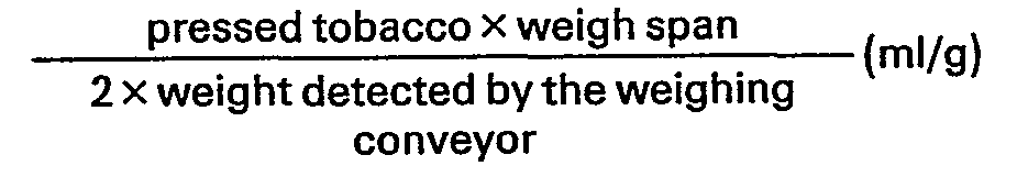
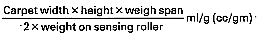
- a microprocessor calculates the filling power as: and makes correction for displacement of the weigh span relative to the carpet height, and also corrects for tobacco moisture content, temperature and belt speed (see UK Patent No. 1495752).
- the calculation is updated for every 3 mm (1 ⁇ 8 in) belt travel and averaged for the previous 5, 10 or 20 minutes.
- the dead weight of the compression unit gives a pressure of 1 psi (0.07 kg/cm 2 ) on the tobacco.
- Additional pressure can be applied by the roller .
- Each 35 psig (2.4 kg/cm 2 ) of air pressure applies a further 1 psig (0.07 kg/cm 2 ) to the tobacco.
- a precision air gauge calibrated up to 100 psig (7.0 kg/cm 2 ) indicates the air pressure.
Landscapes
- Physics & Mathematics (AREA)
- Health & Medical Sciences (AREA)
- Life Sciences & Earth Sciences (AREA)
- Chemical & Material Sciences (AREA)
- Analytical Chemistry (AREA)
- Biochemistry (AREA)
- General Health & Medical Sciences (AREA)
- General Physics & Mathematics (AREA)
- Immunology (AREA)
- Pathology (AREA)
- Manufacturing Of Cigar And Cigarette Tobacco (AREA)
- Manufacture Of Tobacco Products (AREA)
Description
- This invention relates to apparatus for the continuous measurement of the bulk density of particulate material, more particularly cut tobacco.
- UK Patent No. 1 495 752 discloses a method for the continuous measurement of the bulk density of tobacco by means of a variable speed weighing conveyor and rectangular column feed, with the two larger walls formed by conveyor belts driven at the same speed as the weighing conveyor belt.
- An alternative form of column was described with smooth fixed walls and two pinch rolls at the outlet of the column driven with a surface speed equal to the weighing conveyor belt speed.
- The specification of UK Patent No.1 1 495 752 includes reference to the laboratory cylinder volume method of measuring the bulk density of tobacco which is to measure the volume of a fixed weight of tobacco in a vertical cylinder after compression by a free falling piston of fixed weight for a fixed time.
- The size of cylinder and weight of piston vary between manufacturers giving pressure from 1 to 3 psi, (7 to 21 kPa) the higher pressure being used with smaller diameter cylinders.
- The bulk compresses at a diminishing rate and the time is selected to give a nearly static volume. The density achieved is typically 0.25 gm/cc (referred to as a cylinder volume of 4 cc/gm) and matches the density of a cigarette.
- It is found in a particular apparatus with 1.5 psi pressure (10 kPa) and 5 minute compression time that 90% of the density is achieved in 30 secs.
- For the continuous measurement described above, with a 16" x 8" (400 mm x 200 mm) column, a tobacco level controlled to 36" (900 mm) high and 2,200 lbs/hr (1000 kg/h) flow rate, the "settling time" or time through the column is 25 secs and the measured density only 0.11 gm/ cc, (9 cc/gm cylinder volume.
- The level in the column is held constant independent of flow rate by a level detector which controls the speed of the weighing conveyor belt to maintain the level. The pressure on the tobacco at the bottom of the column due to the "head" of tobacco is less than 0.14 psi (1 kPa), ignoring friction.
- An object of the invention is to improve the method of continuous measurement of bulk density material as described in UK Patent No. 1495 752 by matching the laboratory test more nearly and achieving similar densities.
- After compensation for moisture content, temperature and settling time (belt speed), there is a correlation with the laboratory cylinder column test.
- According to the invention there is provided an apparatus for the continuous measurement of tobacco filling power of a moving mass of tobacco comprising support frames (52), an endless belt weighing conveyor (11) carried on said frames and having a compression zone and a weigh span downstream of the compression zone, means (10) for feeding the tobacco to said compression zone, and transducer means (63) provided at the weigh span for producing signals proportional to material weight characterized in that said compression zone comprises a compression unit including a carriage (30) suspended on a supporting framework (F) above the weighing conveyor (11), at a position downstream of the position at which tobacco is fed onto said weighing conveyor (11), a series of rollers (33) on axes extending transverse to the direction of movement of the weighting conveyor, and a belt (34) embracing said rollers (33) to give a continuous surface adjacent the weighing conveyor in the compression zone, and springs or pneumatic cylinders (39, 40) provided between the supporting framewbrk (F) and the carriage (30) to urge said compression unit (12) towards said weighing conveyor (11), a position transducer (41) is connected to said unit for indicating the height of the compressed material at the outlet of the compression zone; means are provided which use the measured height and weight to calculate the value of the filling power from the formula:
- tobacco mass width x height of the com-
- The series of rollers occupy a length of conveyor sufficient to give appreciable compression time, e.g., 3' (900 mm) in the above example gives 25 secs.
- The belt may be driven with a surface speed equal to the weighing conveyor belt speed and additional rollers may be mounted below the weighing conveyor to carry the load.
- The belt gives a continuous surface and prevents tobacco getting between the rollers. The belt may be driven via a terminal roller and the other rollers follow.
- The rollers and belt are free to move between two side walls, which may be extensions of the column side walls and the same distance apart.
- The end roller adjacent the weigh span may be connected to a position transducer so that its height above the weighing conveyor belt can be measured continuously.
- Should the weight of the rollers or the belt be insufficient to give the pressure of 1 to 2 psi (7 to 14 kPa) required which on a 36" (900 mm) length x 16" (400 mm) width amounts to a total load of 576 to 1152 Ibs (262 to 524kg), additional loading may be applied to each roller by the springs or pneumatic cylinders with accurately controlled air pressure, or preferably bellows to remove friction.
- The carriage, which is free to move vertically as a whole, may be loaded by four air cylinders. This gives a consistent but not uniform pressure.
- A more uniform pressure can be achieved by arranging the rollers in a curved path to match the compression of the tobacco.
- The carriage may be pivoted at the feed end and free to move vertically at the discharge end. Tis simplifies the drive but effectively halves the compression time.
- Since the compression rollers and belt have to operate freely between side walls, the rollers may be divided to provide two internal bearing points and the belt fitted with internal vee belt guides which run in grooves in the rollers to maintain precise tracking. The band is of heavy gauge to provide support between the pressure rollers. Alternatively, a timing belt with flanged pulleys could be used.
- The compression belt could be driven from the weighing conveyor by an articulated drive, but is more easily driven by a separate geared motor. If both the weighing conveyor and compression belt motors are synchronous, they can be driven at the same speed by a common variable frequency inverter.
- Since it is difficult to spread tobacco uniformly over wide conveyors and wide columns, the system is less satisfactory with large throughputs. Since also it is desirable to have long settling and compression times, the system is best suited to low feed rates below 2,200 Ibs/hr (1000 kg/h). So for-high throughputs it is preferable therefore to make the measurement in a by-pass carrying a part of the total tobacco flow.
- Since the tobacco is compressed to double the normal density for this stage of the process, it may be desirable to minimise the amount of tobacco in the by-pass. This could be achieved by lengthening the compression time and/or by mi- niaturising the equipment, e.g., for the 16" x8" column (400 x 200 mm), a compression time of 5 minutes would require a belt speed of approx. 7"/min. (3 mm/sec) and a tobacco flow of approx. 220 lbs/hr (100 kg/h) alternatively an 8" x 4" (200 mm x 100 mm) column with 18" (450 mm) level, 18" (450 mm) compression zone, 18" (450 mm) weigh span and 1 min. compression time would require a flow of approx. 250 lbs/hr (110 kg/h).
- In general, the larger equipment is easier to feed. A typical main flow is 10,000 Ibs/hr (4500 kg/ h) so 200 Ibs/hr (115 kg/h) represents 2%. Removing this small proportion from the main flow as a representative sample is achieved by the diversionary chute, which diverts the whole flow for a short period of say 1 second every 50 seconds.
- The resulting approximate 31b. (1.5 kg) portion is spread by a climbing vibrating conveyor and fed into the column over a period of approximately 5 seconds, where it occupies approximately 6" (150 mm) height.
- Such a by-pass system has the advantage that the weighing conveyor, pinch rolls and compression belt can be run at constant speed and a single level control used in the column to demand a portion of tobacco each time it is uncovered, thus generating a constant volume flow.
- The invention will now be described by way of example with reference to the accompanying drawing in which:
- Fig. 1 is a perspective view of the apparatus for the continuous measurement of the density of a bulk of tobacco being conveyed, and
- Fig. 2 is schematic side elevation of a portion of the apparatus comprising a weighing, conveyor, compression unit and metering tube.
- The apparatus of the example described is designed to handle about 100 kg/h (220 Ibs/hr) of cooled cut tobacco in a by-pass to the main flow and apply pressure of up to 3 psi (21 kPa) for a period of 5 minutes to simulate the cylinder volume filling power measurement.
- The machine runs at a fixed speed (except for emptying the system at the end of a run) and draws samples from the main flow as required to maintain a continuous flow through the measuring equipment.
- The apparatus comprises a
metering tube 10 disposed over one end of aweigher conveyor 11. Arranged above the weighing conveyor is acompression unit 12. The metering tube is fed by avibratory conveyor 13 receiving samples of the main flow of tobacco to be continuously monitored by way of adiverter 14 andchute 15 disposed between two horizontally disposedconveyors conveyor 16 by way of adoffer 18 and adelivery chute 19. - The various mechanical, pneumatic and electric actuators to be described later are controlled from a control cubicle C.
- The
metering tube 10, rectangular in cross section preferably measuring 200 x 400 mm (8" x 16"), is made of stainless steel sheet and provides a constant volume flow to the weighing conveyor and thecompression unit 12. - The upper end of the
tube 10 is fitted with an oscillating deflector 20 (see Figure 2) powered by a 0.09 kW (⅛ hp) 60 rpm geared motor (not shown) to ensure uniform filling of the tube over the 200 mm (8") dimension. - Windows 22 are fitted in the tube sides with
photo cell detectors 23 to control start up and diversion of tobacco from themain conveyor - A pair of
pinch rolls 24, 25 driven by a 0.09 kW (% hp) 3.3 rpm synchronous gearedmotor 26 to give the same surface speed as the weighing conveyor is fitted at the lower end of thetube 10 to ensure a steady flow onto the weighingconveyor 11. - Since the tobacco carpet on the weighing conveyor reflects the shape of the column, it is preferable to chamfer the outer corners of the column to prevent tobacco getting between the belt or rollers and the side walls.
- A thermistor
temperature sensor probe 21 projects into the tobacco stream at the base of the metering tube to measure tobacco temperature. - The
compression unit 12, 760 mm (30") long 400 mm (16") wide comprises a carriage 30 with largediameter end rolls motor 35 to give the same speed as the belt of the weighing conveyor. - The carriage 30 is supported above the
weighing conveyor 11 from a framework shown generally at F by twolink arms 36 connected by atorque tube 37 and two brackets 38, so that the carriage is free to move vertically. - The carriage floats on the surface of the tobacco between two fixed low friction side plates (high density polyethylene) not shown. Additional pressure in the range 1 to 3 psi (7 to 21 kPa) is applied by two low friction roller
diaphragm air cylinders 39, 40 fed with air from a precision air set and gauge (not shown). - The thickness of the tobacco carpet at the delivery end roller of the compression unit is measured by a
position transducer 41. - The weighing
conveyor 11 comprises anendless weigh belt 50, 750 mm (30") wide carried from the conveyor support frames 52 by two end rolls 53, 54 disposed at 2550 mm (100") centres. The upper run of the belt passes over two spaced apartrollers belt 50 passes over a trackingroller 57, controlled by alinear actuator 58, and aroller 59 on a fixed axis. Theend roller 54 is driven at 160 mm/ min (6.3"/min) from 0.09 kW (Va hp) 3.3. rpm synchronous gearedmotor 60. The weigh span, 760 mm (30") is defined by theend roller 65 of the series ofrollers 61 on fixed axes extending beneath the compression unit androller 56. Aweight sensing roller 62 is arranged midway between saidend roller 65 and theroller 56 and is carried by a weigh beam (not shown) mounted on frictionless flexure pivots. The weight is sensed by a strain gaugetype load cell 63. - The
weigh belt 50 may be tracked automatically by a belt edge detector and steering roller in the return run of the belt. - The
doffer 18 is adjustable in height and is driven by belt from a 0.09 kW rpm geared motor to assist in the opening of the compressed tobacco. - Belt travel speed is determined by an optical encoder on the shaft of the
end roller 54 and is used to correct for the displacement of the carpet height and weight measurements. - An infra red moisture meter (e.g., Quadrabeam made by Moisture Systems Inc. Boston, Massachusetts, USA) 66 is mounted on the framework over the weigh span.
- A diverter 14 (see Figure 1) in the main flow conveyor system enables 0.5 to 5 second samples to be removed according to flow rate, e.g., a 1 second sample from a 5450 kg/hr (12,000 Ib/hr) flow rate is 1.5 kg (3.3 lbs) or approx. 150 mm (6") in the metering tube.
- The diversion chute enables samples of no more than 1.5 kg (3.3 lbs) to be removed from the main flow of tobacco. To be representative these samples must be a cross-section of the whole flow and not a sample from one side.
- The vibrating
conveyor 13 may be fitted with deflectors to spread the tobacco sample and ensure that themetering tube 10 is filled as uniformly as possible. - A sample is initiated by exposure of the photo
cell level detectors 23 in themetering tube 10. Thediverter 14 is then opened for a pre-set time. A further sample cannot be initiated until a further pre-set time has elapsed, which is greater than the time the sample takes to convey from the diverter to the tube. - The tobacco takes 20 minutes to pass through the equipment, so a speed-up by a factor of
x 10 is provided to clear the equipment of tobacco at the end of a run. - To achieve this speed-up the
pinch rollers 24, compression belt 34 and weighbelt 50 are all driven in synchronisation from a single 0-120 Hz variable frequency inverter with two preset output frequencies. To empty the equipment at the end of a run in approx. 2 minutes the maximum high frequency of 120 Hz is selected. - For filling power measurement a lower frequency of 12 Hz is selected to give a compression time of 5 minutes and a flow rate of 220 lbs/hr (100 kg/h). The frequency of drive belt ratio can be adjusted to give shorter or longer compression times with corresponding flow rates.
- The control cubicle C houses the motor switch gear, the filling power computation, level control timers and displays.
- A microprocessor calculates the filling power as:
- The calculation is updated for every 3 mm (⅛ in) belt travel and averaged for the previous 5, 10 or 20 minutes.
- All the variables can be displayed digitally and a three pen chart recorder continuously records the filling power and any other two variables. 4-20 mA isolated signals are provided for each of the measured variables which are calibrated and displayed as follows:

- The dead weight of the compression unit gives a pressure of 1 psi (0.07 kg/cm2) on the tobacco.
- Additional pressure can be applied by the roller .
diaphragm air cylinders 39, 40 and is fixed by the precision air set. Each 35 psig (2.4 kg/cm2) of air pressure applies a further 1 psig (0.07 kg/cm2) to the tobacco. A precision air gauge calibrated up to 100 psig (7.0 kg/cm2) indicates the air pressure.
Claims (12)

Applications Claiming Priority (2)
| Application Number | Priority Date | Filing Date | Title |
|---|---|---|---|
| GB8216028 | 1982-06-02 | ||
| GB8216028 | 1982-06-02 |
Publications (3)
| Publication Number | Publication Date |
|---|---|
| EP0095867A1 EP0095867A1 (en) | 1983-12-07 |
| EP0095867B1 EP0095867B1 (en) | 1986-01-08 |
| EP0095867B2 true EP0095867B2 (en) | 1990-01-10 |
Family
ID=10530784
Family Applications (1)
| Application Number | Title | Priority Date | Filing Date |
|---|---|---|---|
| EP83302866A Expired EP0095867B2 (en) | 1982-06-02 | 1983-05-19 | Apparatus for the continuous measurement of bulk density material such as cut tobacco |
Country Status (5)
| Country | Link |
|---|---|
| US (1) | US4510808A (en) |
| EP (1) | EP0095867B2 (en) |
| JP (1) | JPS5982075A (en) |
| CA (1) | CA1208663A (en) |
| DE (1) | DE3361772D1 (en) |
Families Citing this family (13)
| Publication number | Priority date | Publication date | Assignee | Title |
|---|---|---|---|---|
| GB2373860B (en) * | 2001-03-28 | 2004-12-15 | Reflowtech Internat Ltd | Monitoring system |
| US7290447B1 (en) | 2003-10-07 | 2007-11-06 | Bj Services Company | Density measuring apparatus containing a densimeter and a method of using the same in a pipeline |
| DE10348717B4 (en) * | 2003-10-16 | 2006-09-21 | Hauni Primary Gmbh | Container for tobacco material |
| US9080929B2 (en) * | 2010-05-10 | 2015-07-14 | Newcastle Innovation Limited | Parallel belt sampler |
| ITBO20100423A1 (en) * | 2010-06-30 | 2011-12-31 | Azionaria Costruzioni Acma Spa | MACHINE AND METHOD OF FORMING FIBER MATERIAL SPOTS. |
| WO2016157414A1 (en) * | 2015-03-31 | 2016-10-06 | 日本たばこ産業株式会社 | Tobacco-material bulkiness measuring device and bulkiness measuring method |
| CN106959146B (en) * | 2016-01-12 | 2022-11-22 | 泉州装备制造研究所 | An on-line detection device for the uniformity of stone material during artificial stone processing |
| CN107621432A (en) * | 2017-08-11 | 2018-01-23 | 红云红河烟草(集团)有限责任公司 | Evaluation and detection method for bulk density of cut tobacco |
| AU2017101725A4 (en) * | 2017-12-06 | 2018-01-18 | Dismov Pty Ltd | Apparatus and methods for setting a grind coarseness |
| CN109870386B (en) * | 2019-04-03 | 2024-06-07 | 浙江省工程物探勘察设计院有限公司 | Sample density testing system for rock-soil investigation test |
| DE102019114033A1 (en) * | 2019-05-26 | 2020-11-26 | Dieffenbacher GmbH Maschinen- und Anlagenbau | Monitoring device for detecting at least one material component in comminuted materials, conveyor system for comminuted materials and methods for monitoring comminuted materials |
| CN110514553B (en) * | 2019-09-24 | 2021-10-22 | 中国烟草总公司郑州烟草研究院 | On-line detection method for bulk density of cut tobacco material on conveyor belt |
| CN113003148A (en) * | 2021-02-23 | 2021-06-22 | 中国烟草总公司郑州烟草研究院 | Tobacco material mass flow measurement and control method based on laser scanning |
Family Cites Families (9)
| Publication number | Priority date | Publication date | Assignee | Title |
|---|---|---|---|---|
| CH419641A (en) * | 1964-06-10 | 1966-08-31 | Sig Schweiz Industrieges | Method and device for the continuous determination of the bulk density of flowable, in particular powdery or granular material |
| FR2250435A5 (en) * | 1973-07-13 | 1975-05-30 | Henry Et Cie S A | Balance to monitor density of expanded beads - by continually weighing set volumes of sample pellets |
| GB1495752A (en) | 1974-03-12 | 1977-12-21 | Amf Inc | Continuous measurement of the bulk density of particulate material such as cut tobacco |
| DE2441832A1 (en) * | 1974-08-31 | 1976-03-11 | Hauni Werke Koerber & Co Kg | PROCEDURE AND ARRANGEMENT FOR CAPACITIVE TESTING OF TOBACCO DENSITY IN THE ENDS OF ROD-SHAPED ARTICLES OF THE TOBACCO PROCESSING INDUSTRY |
| JPS534157U (en) * | 1976-06-28 | 1978-01-14 | ||
| US4170251A (en) * | 1976-11-03 | 1979-10-09 | Proctor & Schwartz, Inc. | Method and apparatus for determining the weight and moisture content of materials |
| DE2841470A1 (en) * | 1978-09-23 | 1980-04-03 | Hauni Werke Koerber & Co Kg | METHOD AND ARRANGEMENT FOR FORMING A WEIGHT CONSTANT TOBACCO FLOW |
| DE2841494A1 (en) * | 1978-09-23 | 1980-04-03 | Hauni Werke Koerber & Co Kg | METHOD AND ARRANGEMENT FOR CONTINUOUSLY DETECTING THE SHEET WEIGHT OF GRAIN, FIBROUS OR LEAF-BASED GOODS |
| DE3207124A1 (en) * | 1981-03-21 | 1982-09-30 | Hauni-Werke Körber & Co KG, 2050 Hamburg | Method and machine for producing rod-shaped smoking articles |
-
1983
- 1983-05-19 EP EP83302866A patent/EP0095867B2/en not_active Expired
- 1983-05-19 DE DE8383302866T patent/DE3361772D1/en not_active Expired
- 1983-05-26 US US06/498,354 patent/US4510808A/en not_active Expired - Fee Related
- 1983-05-26 CA CA000429012A patent/CA1208663A/en not_active Expired
- 1983-06-02 JP JP58098742A patent/JPS5982075A/en active Pending
Also Published As
| Publication number | Publication date |
|---|---|
| EP0095867B1 (en) | 1986-01-08 |
| DE3361772D1 (en) | 1986-02-20 |
| EP0095867A1 (en) | 1983-12-07 |
| CA1208663A (en) | 1986-07-29 |
| US4510808A (en) | 1985-04-16 |
| JPS5982075A (en) | 1984-05-11 |
Similar Documents
| Publication | Publication Date | Title |
|---|---|---|
| EP0095867B2 (en) | Apparatus for the continuous measurement of bulk density material such as cut tobacco | |
| US3968904A (en) | Continuous measurement of the bulk density of particulate material | |
| KR950001804B1 (en) | Method and apparatus for continuous division of bread dough | |
| FI83818C (en) | ANORDNING FOER AVVAEGD DOSERING AV GRANULAERA ELLER PULVERFORMIGA PRODUKTER. | |
| JP2720374B2 (en) | Bread dough quality measurement method and production quantity quantification method | |
| CA2281533C (en) | Computer controlled portioning machine | |
| US3718197A (en) | Conveyor belt weighing device | |
| EP0174168A1 (en) | Method of continuously measuring a successively conveyed lengthy body | |
| CN104501922B (en) | The electronic measurement of check weighing scale is weighed unit | |
| JPH0630876B2 (en) | A device for detecting the thickness of lumps of ham in a ham slice machine. | |
| JPH06194214A (en) | Inspecting and weighing device | |
| US4063456A (en) | Method and a device for continuously measuring a flow of material | |
| JPS58149670A (en) | Method and apparatus for measuring internal pressure of cigarette rod | |
| JPS60110237A (en) | Dough continiuous metering and dividing method and apparatus | |
| US5232713A (en) | Apparatus for continuously dividing bread dough | |
| JPS6158140B2 (en) | ||
| JPH074793B2 (en) | Device and method for automatically cutting meat or fish material | |
| US7154055B2 (en) | Method and apparatus for dividing portions | |
| EP0095866A1 (en) | Apparatus for slicing and feeding tobacco | |
| RU2027151C1 (en) | Weight proportioner | |
| JPH09210754A (en) | Weighing/cutting method of synthetic rubber and apparatus thereof | |
| CN204373749U (en) | The electronic measurement of checking weight weigh is weighed unit | |
| JP2000245329A (en) | Method and apparatus for feeding weighed dough | |
| SU1672220A1 (en) | Apparatus for continuous volume bulk materials measurement | |
| SU979875A1 (en) | Weigher batcher |
Legal Events
| Date | Code | Title | Description |
|---|---|---|---|
| PUAI | Public reference made under article 153(3) epc to a published international application that has entered the european phase |
Free format text: ORIGINAL CODE: 0009012 |
|
| AK | Designated contracting states |
Designated state(s): DE GB IT |
|
| 17P | Request for examination filed |
Effective date: 19831123 |
|
| GRAA | (expected) grant |
Free format text: ORIGINAL CODE: 0009210 |
|
| AK | Designated contracting states |
Designated state(s): DE GB IT |
|
| REF | Corresponds to: |
Ref document number: 3361772 Country of ref document: DE Date of ref document: 19860220 |
|
| ITF | It: translation for a ep patent filed | ||
| PLBI | Opposition filed |
Free format text: ORIGINAL CODE: 0009260 |
|
| PLBI | Opposition filed |
Free format text: ORIGINAL CODE: 0009260 |
|
| 26 | Opposition filed |
Opponent name: B.A.T. CIGARETTENFABRIKEN GMBH Effective date: 19860718 |
|
| 26 | Opposition filed |
Opponent name: HAUNI-WERKE KOERBER & CO. KG Effective date: 19860804 |
|
| PLAB | Opposition data, opponent's data or that of the opponent's representative modified |
Free format text: ORIGINAL CODE: 0009299OPPO |
|
| R26 | Opposition filed (corrected) |
Opponent name: B.A.T. CIGARETTENFABRIKEN GMBH * 860804 KOERBER AG Effective date: 19860718 |
|
| PUAH | Patent maintained in amended form |
Free format text: ORIGINAL CODE: 0009272 |
|
| STAA | Information on the status of an ep patent application or granted ep patent |
Free format text: STATUS: PATENT MAINTAINED AS AMENDED |
|
| 27A | Patent maintained in amended form |
Effective date: 19900110 |
|
| AK | Designated contracting states |
Kind code of ref document: B2 Designated state(s): DE GB IT |
|
| ITF | It: translation for a ep patent filed | ||
| PGFP | Annual fee paid to national office [announced via postgrant information from national office to epo] |
Ref country code: GB Payment date: 19910416 Year of fee payment: 9 |
|
| PGFP | Annual fee paid to national office [announced via postgrant information from national office to epo] |
Ref country code: DE Payment date: 19910426 Year of fee payment: 9 |
|
| ITTA | It: last paid annual fee | ||
| PG25 | Lapsed in a contracting state [announced via postgrant information from national office to epo] |
Ref country code: GB Effective date: 19920519 |
|
| GBPC | Gb: european patent ceased through non-payment of renewal fee |
Effective date: 19920519 |
|
| PG25 | Lapsed in a contracting state [announced via postgrant information from national office to epo] |
Ref country code: DE Effective date: 19930202 |
|
| PLAB | Opposition data, opponent's data or that of the opponent's representative modified |
Free format text: ORIGINAL CODE: 0009299OPPO |