EP0095761A2 - Ensemble de ressorts - Google Patents
Ensemble de ressorts Download PDFInfo
- Publication number
- EP0095761A2 EP0095761A2 EP83105291A EP83105291A EP0095761A2 EP 0095761 A2 EP0095761 A2 EP 0095761A2 EP 83105291 A EP83105291 A EP 83105291A EP 83105291 A EP83105291 A EP 83105291A EP 0095761 A2 EP0095761 A2 EP 0095761A2
- Authority
- EP
- European Patent Office
- Prior art keywords
- portions
- connecting rod
- spring
- coil spring
- base plate
- Prior art date
- Legal status (The legal status is an assumption and is not a legal conclusion. Google has not performed a legal analysis and makes no representation as to the accuracy of the status listed.)
- Granted
Links
Images

Classifications
-
- A—HUMAN NECESSITIES
- A47—FURNITURE; DOMESTIC ARTICLES OR APPLIANCES; COFFEE MILLS; SPICE MILLS; SUCTION CLEANERS IN GENERAL
- A47C—CHAIRS; SOFAS; BEDS
- A47C23/00—Spring mattresses with rigid frame or forming part of the bedstead, e.g. box springs; Divan bases; Slatted bed bases
- A47C23/04—Spring mattresses with rigid frame or forming part of the bedstead, e.g. box springs; Divan bases; Slatted bed bases using springs in compression, e.g. coiled
- A47C23/05—Frames therefor; Connecting the springs to the frame ; Interconnection of springs, e.g. in spring units
Definitions
- the present invention relates to a spring unit used for a mattress or a box spring.
- a conventional spring unit used for a mattress or a box spring is known to have the following structure.
- Each of a plurality of main springs is made of a single wire.
- Each main spring has a straight rod portion and a pair of spring portions such that upper ends of the spring portions are coupled to two ends of the straight rod portion, respectively.
- the plurality of main springs are disposed on a rectangular base plate such that the straight rod portions thereof are at right angles to each other, forming a matrix. Lower ends of the spring portions are thus disposed around a periphery of the base plate and are fixed to the base plate.
- the straight rod portions of the main springs that are disposed in a matrix form are reinforced by intermediate support springs.
- Each intermediate support spring has a straight rod portion and a pair of spring portions in the same manner as the main spring. Upper ends of the spring portions are coupled to the straight rod portions of corresponding main springs, respectively, and lower ends thereof are fixed to the base plate.
- the spring portions of both the main springs and the intermediate support springs comprise torsion bar springs, respectively.
- a torsion bar spring deforms only slightly under a compressive load.
- a compressive load is repeatedly applied to the torsion bar springs, a permanent set tends-to occur.
- the conventional spring unit tends to lose its elasticity at a relatively early stage of use.
- an object of the present invention to provide a spring unit which retains a high elasticity over a long period of time.
- a spring unit comprising:
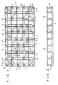
- a spring unit has a base plate 1.
- the base plate 1 comprises a rectangular frame la and a plurality of crosspieces lb arranged to be parallel to short sides of the frame la at equal intervals.
- a plurality of main springs 3, a plurality of intermediate support springs 4, a plurality of corner springs 5, and a frame 6 are disposed on the base plate 1 in a manner to be described later.
- Each main spring 3 has a linear connecting rod portion 8 and a pair of coil spring portions 7. One end of each coil spring portion 7 is connected to a corresponding one of two ends of the connecting rod portion 8.
- Each main spring 3 is made of a single steel wire having a circular sectional profile.
- Each pair of coil spring portions 7 has a structure shown in Fig. 4 in which axes Ll and L2 thereof are parallel to each other.
- Each of straight portions 9 is connected between an end of the connecting rod portion 8 and one end of a corresponding one of the pair of coil spring portions 7.
- the straight portions 9 are at right angles to the connecting rod portions 8.
- the plurality of main springs 3 are disposed on the base plate 1 such that the connecting rod portions 8 thereof are arranged at right angles to each other, forming a matrix.
- the coil spring portions 7 of each main spring 3 are disposed on the frame la of the base plate 1.
- One lower end of each coil spring portion 7 is fixed by a plurality of staples 20 to the frame la, as shown in Fig. 7.
- each connecting rod portion 8 arranged parallel to the long side of the base plate 1 is longer than that arranged parallel to the short side thereof.
- Each intermediate support spring 4 has a linear connecting rod portion 10a and a pair of coil spring portions 10, in the same manner as each main spring 3. One end of each of the coil spring portions 10 is connected to a corresponding one of two ends of the connecting rod portion 10a through a straight portion 11 and a bent portion 12.
- Each intermediate support spring 4 is made of a single steel wire having a circular sectional profile.
- the connecting rod portion 10a of each intermediate support spring 4 is sufficiently shorter than the connecting rod portion 8 of each main spring 3. In other words, the length of the connecting rod portion 10a of each intermediate support spring 4 is predetermined to be subtantially equal to that of a diagonal line of each rectangle formed by the matrix of connecting rod portions 8. As shown in Fig.
- the straight portion 11 is connected between each end of the connecting rod portion 10a and one end of a corresponding one of the pair of coil spring portions 10.
- One of the two straight portions 11 is connected to the corresponding end of the connecting rod portion 10a through the bent portion 12 which is arranged at a right angle to the straight portion 11.
- the connecting rod portion 10a of each intermediate support spring 4 thus substantially corresponds to a diagonal line of each of the above-mentioned rectangles formed by the matrix of connecting rod portions 8 of the main springs 3.
- An arcuated portion of one end of the coil spring portions 10 and one of the straight portions 11 integrally formed therewith, is coupled to the connecting rod portions 8 of corresponding main springs 3 by clips 13.
- each coil spring portion 10 is fastened by staples 20 to one of the plurality of crosspieces lb of the base plate 1.
- a steel wire having a circular sectional profile forms the rectangular frame 6 which has substantially the same size as the base plate 1.
- the frame 6 is fastened by clips 14 to the straight portion 9 of each of the coil spring portions 7 at the periphery of the base plate 1.
- the straight portions 9 and the frame 6 are brought into tight contact with each other and are fixed by the clips 14.
- each corner spring 5 comprises a coil spring portion 15 and a linear connecting rod portion 16 formed integrally with one end of the coil spring portion 15.
- the terminal end of the connecting rod portion 16 is bent at a predetermined angle so as to form a bent portion 17.
- One end of the coil spring portion 15 of the corner spring 5 is fastened by clips 19 to a corresponding corner of the frame 6.
- the other end of the coil spring 15 of the corner spring 5 is fastened by staples 20 to the frame la as shown in Fig. 7.
- the bent portion 17 is fastened by a clip 18 to the connecting rod portion 8 of the corresponding main spring 3.
- each of the clips 13, 14, 18 and 19 is made of a metal strip of a predetermined width, as shown in Fig. 6.
- Each clip is bent around a pair of steel wires so as to fasten the pair of steel wires.
- both ends of the connecting rod portion 8 of each main spring 3 and those of the connecting rod portion 10a of each intermediate support spring 4 are integrally formed with the coil spring portions 7 and 10, respectively.
- the deformation in each of the coil spring portions 7 and 10 due to a compressive load is greater than that in each torsion bar spring.
- the spring unit will not lose its high elasticity at an early stage of use, unlike the conventional spring unit.
- the frame 6 is fastened by the clip 14 to each straight portion 9 formed at one end of the coil spring portions 7 of each main spring 3 such that the linear portions thereof are in contact with each other.
- the contact length between each coil spring portion 7 and the frame 6 is greatly increased compared with the case where coil spring portions 7 do not have straight portions 9. Accordingly, the coil spring portions 7 and the frame 6 will not become loose at an early stage of use since they are firmly fastened by the clips 14.
- the coil spring portions 7 of the main springs 3 are properly reinforced by the frame 6 over a long period of time. Furthermore, since the frame 6 and the coil spring portions 7 do not strike each other, no mechanical noise occurs.
- each straight portion 11 of each intermediate support spring 4 is fastened by a clip 13 to the corresponding connecting rod portion 8 of a main spring 3 such that the linear portions thereof contact each other.
- Each intermediate support spring 4 is firmly fastened to the connecting rod portions 8 of the corresponding main springs 3, thus ensuring the reinforcement of the connecting rod portions 8 of the main springs 3.
- bent portion 17 integrally formed with the connecting rod portion 16 of each corner spring 5 is brought into tight contact with the connecting rod portion 8 of the corresponding main spring 3 and is firmly fastened thereto by a clip 18. As a result, the bent portion 17 and the connecting rod portion 16 are firmly fastened to each other.
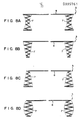
- the spring unit is assembled by the main spring 3 having the cylindrical spring portions 7.
- the spring unit may be assembled by a main spring 3 having spring portions of another type. That is, the spring portions 7 may be formed into an hourglass shape, an inverted conical shape, a conical shape or a barrel shape as shown in Figs. 8A to 8D respectively.
- the main spring unit 3 is made of a single steel wire.
- the main spring unit 3 may consist of two sections each of which is made of a single steel wire.
- each of the two sections may have a linear connecting rod segment and a single coil spring portion, and the linear connecting rod segment of one of the sections may be coupled to the linear connecting rod segment of the other section to form the main spring unit 3 having a single connecting rod portion which consists of the two coupled segments.
Landscapes
- Springs (AREA)
Priority Applications (1)
| Application Number | Priority Date | Filing Date | Title |
|---|---|---|---|
| AT83105291T ATE36229T1 (de) | 1982-05-29 | 1983-05-27 | Federgefuege. |
Applications Claiming Priority (4)
| Application Number | Priority Date | Filing Date | Title |
|---|---|---|---|
| JP92009/82 | 1982-05-29 | ||
| JP9200982A JPS58209310A (ja) | 1982-05-29 | 1982-05-29 | スプリング装置 |
| JP58028230A JPS59155216A (ja) | 1983-02-22 | 1983-02-22 | スプリング装置 |
| JP28230/83 | 1983-02-22 |
Publications (3)
| Publication Number | Publication Date |
|---|---|
| EP0095761A2 true EP0095761A2 (fr) | 1983-12-07 |
| EP0095761A3 EP0095761A3 (en) | 1984-12-05 |
| EP0095761B1 EP0095761B1 (fr) | 1988-08-10 |
Family
ID=26366278
Family Applications (1)
| Application Number | Title | Priority Date | Filing Date |
|---|---|---|---|
| EP83105291A Expired EP0095761B1 (fr) | 1982-05-29 | 1983-05-27 | Ensemble de ressorts |
Country Status (3)
| Country | Link |
|---|---|
| US (1) | US4619445A (fr) |
| EP (1) | EP0095761B1 (fr) |
| DE (1) | DE3377618D1 (fr) |
Cited By (1)
| Publication number | Priority date | Publication date | Assignee | Title |
|---|---|---|---|---|
| KR100843421B1 (ko) * | 2007-02-27 | 2008-07-03 | 삼성전기주식회사 | 5-포트 네트워크의 i/q 재생 장치 |
Families Citing this family (5)
| Publication number | Priority date | Publication date | Assignee | Title |
|---|---|---|---|---|
| US4709906A (en) * | 1986-10-14 | 1987-12-01 | Mizelle Ned W | Furniture seat supports and spring assemblies |
| US5152509A (en) * | 1990-06-22 | 1992-10-06 | Leggett & Platt, Incorporated | Bedding foundation having snap-in place modular wire springs |
| US5509642A (en) * | 1995-03-20 | 1996-04-23 | L&P Property Management Company | Mattress innerspring structure having coaxial coil units |
| US6149143A (en) * | 1995-03-20 | 2000-11-21 | L&P Property Management Company | Spring structure for a mattress innerspring having coaxial coil units |
| US6260223B1 (en) | 1999-12-15 | 2001-07-17 | Leggett & Platt, Incorporated | Pocketed coil spring units |
Citations (2)
| Publication number | Priority date | Publication date | Assignee | Title |
|---|---|---|---|---|
| US3755833A (en) * | 1971-12-15 | 1973-09-04 | Hoover Ball & Bearing Co | Box spring frame |
| US3938204A (en) * | 1971-04-08 | 1976-02-17 | Hoover Ball And Bearing Company | Frame construction for box spring assemblies |
Family Cites Families (6)
| Publication number | Priority date | Publication date | Assignee | Title |
|---|---|---|---|---|
| GB386251A (en) * | 1932-07-20 | 1933-01-12 | Wales Ltd | Improvements in mattresses and the like |
| DE1155218B (de) * | 1958-03-14 | 1963-10-03 | Willi Gerstorfer | Federeinlage fuer Polsterungen od. dgl. |
| US3286281A (en) * | 1965-02-24 | 1966-11-22 | Hoover Ball & Bearing Co | Box spring assembly |
| US3657749A (en) * | 1970-06-22 | 1972-04-25 | Stephen Baliski | Spring assembly |
| US4060862A (en) * | 1976-04-28 | 1977-12-06 | Hoover Ball And Bearing Company | Box spring assembly having serpentine right angle bend springs therein |
| US4371152A (en) * | 1980-01-25 | 1983-02-01 | Hoover Universal, Inc. | Box spring assembly with improved spring installation capability |
-
1983
- 1983-05-27 EP EP83105291A patent/EP0095761B1/fr not_active Expired
- 1983-05-27 DE DE8383105291T patent/DE3377618D1/de not_active Expired
-
1985
- 1985-05-07 US US06/731,604 patent/US4619445A/en not_active Expired - Fee Related
Patent Citations (2)
| Publication number | Priority date | Publication date | Assignee | Title |
|---|---|---|---|---|
| US3938204A (en) * | 1971-04-08 | 1976-02-17 | Hoover Ball And Bearing Company | Frame construction for box spring assemblies |
| US3755833A (en) * | 1971-12-15 | 1973-09-04 | Hoover Ball & Bearing Co | Box spring frame |
Cited By (1)
| Publication number | Priority date | Publication date | Assignee | Title |
|---|---|---|---|---|
| KR100843421B1 (ko) * | 2007-02-27 | 2008-07-03 | 삼성전기주식회사 | 5-포트 네트워크의 i/q 재생 장치 |
Also Published As
| Publication number | Publication date |
|---|---|
| EP0095761B1 (fr) | 1988-08-10 |
| US4619445A (en) | 1986-10-28 |
| EP0095761A3 (en) | 1984-12-05 |
| DE3377618D1 (en) | 1988-09-15 |
Similar Documents
| Publication | Publication Date | Title |
|---|---|---|
| US4685659A (en) | Spring unit | |
| US4664361A (en) | Spring unit | |
| US4251892A (en) | Box spring assembly with arcuate bendable springs | |
| US4548390A (en) | Spring unit | |
| EP0095761A2 (fr) | Ensemble de ressorts | |
| US4921228A (en) | Box spring unit with interlocking spring and grid assembly | |
| US6285013B1 (en) | Heat coil support assembly and method | |
| US5005809A (en) | Spring element for a foundation unit and foundation unit employing a spring element | |
| US4481411A (en) | Electrical heater rack assembly with stand-off insulators | |
| US4253208A (en) | Box spring assembly with basic wire grid | |
| US5558315A (en) | Multi-fold interlockable spring for use in mattress foundation assemblies | |
| US4729550A (en) | Spring module | |
| US4595181A (en) | Bent wire spring unit | |
| US5142716A (en) | Foundation unit with snap-fit modular springs | |
| US5142715A (en) | Foundation unit with snap-fit modular springs | |
| US3864765A (en) | Bedspring and method of making the same | |
| US4721290A (en) | Bent wire spring unit | |
| US4120059A (en) | Furniture spring assembly and method for manufacture thereof | |
| CA1196736A (fr) | Ressort pour matelas ou coussins d'ameublement | |
| US2961667A (en) | Method and structure for the manufacture of spring assemblies | |
| US5149064A (en) | Foundation unit edge support system | |
| US3084353A (en) | Spring assembly | |
| US4796872A (en) | Bent wire spring module | |
| JP2912856B2 (ja) | スプリング装置 | |
| US2559715A (en) | Compression-connecting terminal member |
Legal Events
| Date | Code | Title | Description |
|---|---|---|---|
| PUAI | Public reference made under article 153(3) epc to a published international application that has entered the european phase |
Free format text: ORIGINAL CODE: 0009012 |
|
| 17P | Request for examination filed |
Effective date: 19830623 |
|
| AK | Designated contracting states |
Designated state(s): AT BE CH DE FR GB IT LI LU NL SE |
|
| PUAL | Search report despatched |
Free format text: ORIGINAL CODE: 0009013 |
|
| AK | Designated contracting states |
Designated state(s): AT BE CH DE FR GB IT LI LU NL SE |
|
| GRAA | (expected) grant |
Free format text: ORIGINAL CODE: 0009210 |
|
| AK | Designated contracting states |
Kind code of ref document: B1 Designated state(s): AT BE CH DE FR GB IT LI LU NL SE |
|
| PG25 | Lapsed in a contracting state [announced via postgrant information from national office to epo] |
Ref country code: SE Effective date: 19880810 Ref country code: NL Effective date: 19880810 Ref country code: LI Effective date: 19880810 Ref country code: CH Effective date: 19880810 Ref country code: BE Effective date: 19880810 Ref country code: AT Effective date: 19880810 |
|
| REF | Corresponds to: |
Ref document number: 36229 Country of ref document: AT Date of ref document: 19880815 Kind code of ref document: T |
|
| ITF | It: translation for a ep patent filed |
Owner name: JACOBACCI & PERANI S.P.A. |
|
| REF | Corresponds to: |
Ref document number: 3377618 Country of ref document: DE Date of ref document: 19880915 |
|
| ET | Fr: translation filed | ||
| REG | Reference to a national code |
Ref country code: CH Ref legal event code: PL |
|
| NLV1 | Nl: lapsed or annulled due to failure to fulfill the requirements of art. 29p and 29m of the patents act | ||
| PG25 | Lapsed in a contracting state [announced via postgrant information from national office to epo] |
Ref country code: LU Free format text: LAPSE BECAUSE OF NON-PAYMENT OF DUE FEES Effective date: 19890531 |
|
| PLBE | No opposition filed within time limit |
Free format text: ORIGINAL CODE: 0009261 |
|
| STAA | Information on the status of an ep patent application or granted ep patent |
Free format text: STATUS: NO OPPOSITION FILED WITHIN TIME LIMIT |
|
| 26N | No opposition filed | ||
| ITTA | It: last paid annual fee | ||
| PGFP | Annual fee paid to national office [announced via postgrant information from national office to epo] |
Ref country code: FR Payment date: 19980512 Year of fee payment: 16 |
|
| PGFP | Annual fee paid to national office [announced via postgrant information from national office to epo] |
Ref country code: GB Payment date: 19980518 Year of fee payment: 16 |
|
| PGFP | Annual fee paid to national office [announced via postgrant information from national office to epo] |
Ref country code: DE Payment date: 19980528 Year of fee payment: 16 |
|
| PG25 | Lapsed in a contracting state [announced via postgrant information from national office to epo] |
Ref country code: GB Free format text: LAPSE BECAUSE OF NON-PAYMENT OF DUE FEES Effective date: 19990527 |
|
| GBPC | Gb: european patent ceased through non-payment of renewal fee |
Effective date: 19990527 |
|
| PG25 | Lapsed in a contracting state [announced via postgrant information from national office to epo] |
Ref country code: FR Free format text: LAPSE BECAUSE OF NON-PAYMENT OF DUE FEES Effective date: 20000131 |
|
| PG25 | Lapsed in a contracting state [announced via postgrant information from national office to epo] |
Ref country code: DE Free format text: LAPSE BECAUSE OF NON-PAYMENT OF DUE FEES Effective date: 20000301 |
|
| REG | Reference to a national code |
Ref country code: FR Ref legal event code: ST |