EP0095680A2 - Press for forming sheet material - Google Patents
Press for forming sheet material Download PDFInfo
- Publication number
- EP0095680A2 EP0095680A2 EP83105014A EP83105014A EP0095680A2 EP 0095680 A2 EP0095680 A2 EP 0095680A2 EP 83105014 A EP83105014 A EP 83105014A EP 83105014 A EP83105014 A EP 83105014A EP 0095680 A2 EP0095680 A2 EP 0095680A2
- Authority
- EP
- European Patent Office
- Prior art keywords
- press
- head
- die set
- sheet material
- shaft
- Prior art date
- Legal status (The legal status is an assumption and is not a legal conclusion. Google has not performed a legal analysis and makes no representation as to the accuracy of the status listed.)
- Granted
Links
Images


Classifications
-
- B—PERFORMING OPERATIONS; TRANSPORTING
- B30—PRESSES
- B30B—PRESSES IN GENERAL
- B30B1/00—Presses, using a press ram, characterised by the features of the drive therefor, pressure being transmitted directly, or through simple thrust or tension members only, to the press ram or platen
- B30B1/26—Presses, using a press ram, characterised by the features of the drive therefor, pressure being transmitted directly, or through simple thrust or tension members only, to the press ram or platen by cams, eccentrics, or cranks
-
- B—PERFORMING OPERATIONS; TRANSPORTING
- B26—HAND CUTTING TOOLS; CUTTING; SEVERING
- B26D—CUTTING; DETAILS COMMON TO MACHINES FOR PERFORATING, PUNCHING, CUTTING-OUT, STAMPING-OUT OR SEVERING
- B26D5/00—Arrangements for operating and controlling machines or devices for cutting, cutting-out, stamping-out, punching, perforating, or severing by means other than cutting
- B26D5/08—Means for actuating the cutting member to effect the cut
- B26D5/16—Cam means
-
- B—PERFORMING OPERATIONS; TRANSPORTING
- B29—WORKING OF PLASTICS; WORKING OF SUBSTANCES IN A PLASTIC STATE IN GENERAL
- B29C—SHAPING OR JOINING OF PLASTICS; SHAPING OF MATERIAL IN A PLASTIC STATE, NOT OTHERWISE PROVIDED FOR; AFTER-TREATMENT OF THE SHAPED PRODUCTS, e.g. REPAIRING
- B29C51/00—Shaping by thermoforming, i.e. shaping sheets or sheet like preforms after heating, e.g. shaping sheets in matched moulds or by deep-drawing; Apparatus therefor
- B29C51/26—Component parts, details or accessories; Auxiliary operations
- B29C51/30—Moulds
- B29C51/38—Opening, closing or clamping means
Definitions
- This invention relates to devices employing dies to form sheet material into three-dimensional objects, and more particularly, to a press having a selectively variable dwell time and stroke rate.
- a conventional press includes a pair of dies which are movable between an engaged and a disengaged position. Unformed sheet material is inserted between the two dies, and the dies are then brought into engagement. They are held in engagement with each other for a period of time (herein referred to as the dwell time) during which the three-dimensional container is formed. The dies are then separated, and the formed container is ejected from between the dies.
- An electric motor normally runs the press which raises and lowers the dies.
- the press contains a cam and follower arrangement which translates the rotational movement of the motor into the linear movement of the die head.
- the dwell time during which the dies are in engagement is usually determined by the shape and surface length of the cam. In order to change the dwell time, it is usually necessary to change the cam, which can be a rather time-consuming process.
- Container manufacturers are often called upon to make a wide variety of containers having different size shape and material composition.
- a change in the type of container being manufactured entails a certain amount of expense in adapting the press to form the different container.
- the adaptation, or set up usually involves a change of dies and often a change in the dwell time.
- a dwell time In order to form a container properly, a dwell time must be selected which will allow the dies sufficient time to form a container of that particular size and shape.
- dwell time selection is dependent upon the composition of the material being formed. For example, a different dwell time may be required to form a polystyrene container than to form a similarly shaped paper container. Also, different batches of the same material may require different dwell times to form identical containers properly.
- One factor which influences the dwell time required is the moisture content of the batch of material being formed.
- a further problem associated with machines presently on the market is that most container-forming presses tend to be large and expensive machines. Although these machines can be very cost-effective when employed to make large runs of identical containers, they often become rather cost-ineffective when employed to make small runs of containers of varied size, shape, or material.
- a press includes a frame, a flywheel, a motor for driving the flywheel, and a mechanism to couple the motor to the flywheel.
- a shaft is provided which is coaxial with the flywheel and selectively engageable therewith.
- a clutch is actuable for engaging the shaft to the flywheel. Normally, the clutch is a fluid-actuable clutch, and relies on air pressure to engage and release its mechanical couplings.
- the press includes an upper die and a lower die.
- An eccentric drive such as a scotch yoke, is provided for drivingly connecting the upper die to the shaft. The action of the shaft and the eccentric drive moves the upper die into and out of engagement with the lower die.
- a brake is provided for holding the shaft in a fixed position during the time when the upper die is in engagement with the lower die.
- the lower die is resiliently mounted to face upwardly on a normally stationary base.
- a press for cutting and forming sheet material.
- the press includes a frame and a head mounted for movement on the frame between a blank cutting position and a blank-forming position.
- Cutting means are provided for cutting sheet material, and forming means are provided for forming sheet material.
- the cutting means is operably engaged by the head at a blank-cutting position, and the forming means is operatively engaged by the head at the blank-forming position.
- tranfer means are provided for transferring sheet material between the cutting means and the forming means.
- advancing means are provided for advancing sheet material into the frame.
- One feature of the instant invention is that, through the applicant's flywheel, clutch, and eccentric drive mechanism, the dwell time and stroke rate of the press are easily changed, thereby reducing the down time of the machine caused by the set-up time required to adapt the press to form a different type of container.
- Another feature of the invention resides in the frame which is designed to facilitate servicing of the press and changing of the dies.
- movable entry and exit conveyors are also provided which facilitate servicing of the press.
- Another feature of the invention is the adaptability of the press so as to be used singly or in combination with a plurality of other similar presses. Multiple presses can be driven from a single power source, while retaining the selective controllability of each individual press.
- Another feature of this press is that, since it can be produced less expensively than many conventional presses, and is designed to be used singly or in combination with other presses, smaller operators can initially purchase one press, and add others as their volume increases.
- cutting means are provided which are operatively engaged to the head for cutting sheet material.
- This feature has the advantage of enabling the user of the machine to feed a continuous sheet of material, such as rolled sheet stock, into the press.
- the press includes means for both cutting the sheet material and for forming sheet material into a three-dimensional object.
- a press 10 includes a frame 11 having a base 12, an upstanding wall 14 at one end of the base, and an upstanding wall 16 near the middle of the base '12.
- the walls 14, 16 and base 12 are preferably constructed of rather substantial hot-rolled plate in order to withstand the pressures exerted upon them by the press components supported on them, and the forces exerted by the press 10 in operation.
- Upstanding wall 14 further includes an opening 17 through which an operator can gain access to the pressing area 25.
- housing 18 Contiguous with wall 16 is housing 18 which includes a hingedly mounted door 19 having a handle 20 and latch (not shown) which enable the user to gain access to the inside of the housing 18 for servicing, but which protect the components inside the housing 18 when the door 19 is closed.
- a free-standing control panel 21 which communicates with the press 10 through umbilicals 22, 24 contains a plurality of controls through which the operator controls the actions of the press and adjusts such variables as stroke rate and dwell time, counters by which the operator keeps track of press 10 production, and microprocessors which are in communication with various components of the press.
- the microprocessors receive input from the various components and direct commands to various components based upon the operator's requests and the input received from the various components.
- a compressed air source (not shown) provides air to the press to operate and actuate the parts of the press 10 which are air-driven or actuated.
- Entrance conveyor 30 and exit conveyor 32 are both movable to enable an operator to gain access to the pressing area 25 when servicing components therein.
- Entrance conveyor 30 is pulled upwardly and released downwardly by cables 36 and is guided by rollers 37 along tracks 34. Cables 36 are pulled over pulleys 40 in order to move the entrance conveyor 30 with a force in the same direction as the tracks 34 run.
- the cables 36 are actuated by pneumatic pistons 38.
- Adjustable levelers 39 are threadably engaged into the lower extremities of tracks 34.
- the levelers 39 are inserted into the tracks 34 to halt downward movement of the entrance conveyor 30 during times when the entrance conveyor 30 is being lowered into the operating position.
- the operator can adjust the levelers 39 to ensure that when the entrance conveyor 30 is lowered into its operating position, it will be in vertical alignment with feeding chute 43.
- Fig 1 shows the entrance conveyor 30 in a partially raised position
- Fig. 2 shows the conveyor 30 in a lowered operating position.
- the entrance conveyor 30 further includes upstanding guide rods 42 which serve to position the blanks 26 for feeding them into the pressing area 25 and also serves to maintain the blanks 26 in a neat stack.
- the position of guide rods 42 is laterally and longitudinally adjustable in order to accommodate different-sized blanks 26.
- the blanks 26 are moved individually into the pressing area 25 by the action of pickups 44, 46.
- An additional pickup (not shown) can be added on the entrance conveyor 30 to serve as an intermediate blank 26 stop between the stack and the pressing area 25.
- the inclined angle of the entrance conveyor 30 allows the blanks 26 to fall into the pressing area 25 under the influence of gravity.
- the blanks 26 which are formed by this embodiment of press 10 are precut and, if necessary, prescored.
- exit conveyor 32 is hingedly mounted on hinge 48 which allows the conveyor 32 to be swung aside and thus provide an operator or serviceman with easy access into the pressing area 25.
- a metallic plate 50 and magnet 52 serve to secure the exit conveyor 32 in place when the press 10 is not being serviced.
- Exit conveyor 32 further includes a pair of conveyor belts 54 for moving the formed containers 28 to the end of the conveyor, pickups 56, 58 for stacking the formed containers 28, and guide rods 60 for maintaining the formed containers 28 in a neat stack. The position of guide rods 60 is laterally and longitudinally adjustable.
- a product marker (not shown) is also included for marking a formed container 28 after a predetermined number of containers 28 have been made by the machine.
- the marking of a selected container 28 enables the operator to remove a predetermined number of formed containers 28 from exit conveyor 32.
- an electric motor 62 includes output shaft 64 and output shaft 65, each of which turns a pulley 66, 68, respectively.
- the motor 62 is preferably at least 3 hp if driving a single press, and more powerful if driving multiple presses.
- Pulley 66 turns a belt 70 which partially surrounds the outer surface of flywheel 72, thereby rotating flywheel 72 in the same direction as pulley 66.
- Pulley 68 rotates pulley 74 via a belt 78.
- the rotation of pulley 68 in turn rotates jackshaft 80 which, through pulley 82 and belt 84, rotates flywheel 86 of adjacent press 88.
- Several other presses can be run in a line through common jackshaft 80.
- press 88 is also provided with a control panel (not shown) similar to control panel 20 so that presses 10, 88 can be individually controlled, thereby allowing the operator to form different containers on presses operated off the common jackshaft 80.
- Air tube disk clutch 90 is secured to flywheel 86 so that the driving elements of the clutch 90 rotate coaxially with the flywheel 86.
- Clutch 90 is a preferably multiple plate clutch which is air-actuated via hose 92 which is rotatably mounted in the clutch 90 by connector 94. This allows the clutch housing 96 to rotate while permitting the air hose 92 to remain stationary.
- Clutch housing 96 is secured to flywheel 86 by a plurality of bolts 98.
- the clutch is engaged to the shaft 100 by pumping air under pressure into the air bladder 102, causing the bladder 102 to expand against pressure plate 104. The movement of pressure plate 104 forces the driving disks 106 into frictional engagement with the driven plates 108 which are coupled to the driven shaft 100.
- release springs act to bias the driving disks 106 out of engagement with the driven plates 108 to minimize friction and contact between the driving disks 106 and driven plates 108 when the clutch 90 is disengaged from the shaft 100.
- the clutch 90 is biased to be normally disengaged from shaft 100, and engages the shaft 100 only upon command.
- Shaft 100 is journaled on bearings 110, 112, the outer housings of which are securely attached by bolts 114 to the insides of walls 14, 16, respectively.
- the shaft 100 must be strong enough to support the weight exerted upon the shaft 100 by the clutch 90, flywheel 86, and other components.
- the bearings 110, 112 and bolts 114 must be strong enough to support the shaft 100 and the components supported by the shaft.
- Brake 115 is mounted to the outer surface of wall 14 and is positioned proximate to shaft 100 to engage shaft 100. Brake 115 is spring-biased to be normally in engagement with shaft 100.
- the brake 115 includes an air release which, when applied, has sufficient strength to release the brake 115 from its spring-biased engagement with shaft 100, thereby allowing shaft 100 to rotate freely.
- the brake 115 engages shaft 100 when the press 10 is not running, and at any time during operation of the press 10 when the clutch 90 is disengaged from the shaft 100.
- the brake 115 is only released from engagement with the shaft 100 when the clutch 90 is engaged to the shaft 100. Press 10 will operate and will form containers 28, however, without the need of a brake 115.
- Rotary transducer 122 is in communication with the control panel 21 to inform the control panel 21 of the rotational position of the shaft 100. As will be discussed below, the rotational position of the shaft 100 is directly translatable into the vertical position of the upper die 124. The rotary transducer 122 is thereby capable of informing the control panel 21 of the vertical position of the upper die 124.
- an eccentric 126 is collared onto the shaft 100 through an opening 128 in the eccentric 126.
- the eccentric 126 is generally circular in shape. Opening 128 is offset from the center of the eccentric 126, thereby causing the diameter of the rotational path of eccentric 126 to be larger than the diameter of the eccentric 126.
- the eccentric 126 maintains its relative rotational position upon the shaft 100 by the insertion of a key 130 into corresponding openings 132, 134 of the shaft 100 and eccentric 126, respectively.
- the eccentric 126 rotates coaxially with the shaft 100 in block 136.
- the exterior of block 136 is substantially rectangular in shape, having exterior length and width dimensions which are approximately equal to each other.
- Block 136 contains a generally circular opening 137, sized to slidably receive eccentric 126, and within which eccentric 126 rotates, imparting an eccentric path of travel to block 136, which results in reciprocating movement of head 138, within which block 136 is slidably contained.
- the block 136 is approximately as thick as eccentric 126.
- Head 138 includes side plates 140, 142, bottom plate 144, top plate 145, front plate 146, and rear plate 148.
- Top plates 145 each include oblong-shaped openings 150 having their longest dimension in a direction parallel to arrow 152, shown in Fig. 2.
- the oblong-shaped openings 150 are provided in the side plates 140, 142 to provide clearance for the shaft 100 as the head travels in the directions indicated by arrow 152.
- Top plate 145 includes an inlet port 154 for lubricant line 156 and an outlet port 158 for lubricant line 160 through which lubricant is circulated in the area between the inner surfaces of the head 138 and the outer surfaces of the block 136, and also in the area between the inner surface of the block 136 and outer surface of the eccentric 126.
- Front plate 146 and rear plate 148 include V-shaped tongues 162, 164 which are sized to be slidably received by V-shaped grooves 166, 168 cut in longitudinal bars 170, 172, all of which extend in a direction parallel to that indicated by arrow 152.
- Grease grooves 153 are provided on V-shaped tongues 162, 164 to retain lubricant and thereby reduce friction between the V-shaped tongues 162, 164 and the V - shaped grooves 166, 168. The retention of lubricant enhances the slidability of the tongues 162, 164 along the V-shaped grooves 166, 168.
- Longitudinal bars 170, 172 are securely attached to planar cross members 174, 176, respectively.
- Planar cross members 174, 176 extend between walls 14, 16 and are securely attached thereto by bolts 178.
- bottom plate 144 Attached to bottom plate 144 is die mounting plate 180, to which the upper die 124 is removably secured by bolts 182.
- mounting plate 180 is of a universal type which will fit most or all of the dies 124 commonly used in the industry.
- upper portion 183 of upper die 124 can be equipped with heating elements (not shown) which serve to heat the upper die 124 and thereby quicken the formation of flat blanks 26 into formed containers 28.
- Upper die 124 includes air jets (not shown) which prevent the formed containers 28 from sticking to the upper die 124 after being pressed thereby.
- Lower die 184 is mounted onto floating base 186 by bolts 187.
- Lower die 184 illustrated in Figs. 1 and 3 is a telescoping die.
- Floating base 186 may be equipped with heating elements (not shown) to facilitate formation of containers 28.
- Mounted to lower die 184 are a pair of upstanding stops 185 which are sized and positioned to stop a blank 26 from sliding past the lower die 184, but to allow a formed container to slide therethrough.
- the width of a formed container 28 having raised portions is generally narrower than the flattened blank 26 from which it is formed, thereby allowing a formed container 28 to slide through an opening through which a blank 26 would not pass.
- Floating base 186 is slidably mounted on support rods 188 to stationary base 190, such that position of the floating base 186 is vertically movable.
- air cushion 200 Interposed between floating base 186 and stationary base 190 is air cushion 200 upon which the floating base 186 rests and which preferably is constructed out of a thick pliable rubber which is strong enough to withstand the pressure exerted on it by the floating base 186 and lower die 184 through the action of the upper die 124.
- Air cushion 200 also serves to counteract the force of gravity by biasing floating base 186 away from stationary base 190.
- an insulating sheet 202 should be interposed between the floating base 186 and the air cushion 200.
- the insulating sheet 202 helps to retard premature cracking and drying of the rubber in air cushion 200, and aids in preventing rupture of air cushion 200 caused by the rubber in the air cushion 200 becoming melted due to the heat of the floating base 186.
- Feeding chute 43 and exit chute 204 are mounted onto lower die 184 and are vertically movable therewith. Entrance chute 206 and exit chute 208 are stationarily mounted to one or both of upstanding walls 14, 16. Alternatively, feeding chute 43 and removing chute 204 can be lengthened to capture blanks 26 directly from the entrance conveyor 30 in the case of the feeding chute 43, and to deliver formed containers 28 directly to the exit conveyor 32 in the case of the removing chute 204.
- An opening 172 is provided in upstanding wall 14 to enable the operator to gain access to the pressing area 25 to change the upper and lower dies 124, 184.
- FIG. 11 Another embodiment of the instant invention is shown in Fig. 11 wherein press 210 is adapted for cutting and forming sheet material.
- entrance conveyor 33, pulley 40, pneumatic pistons 38, tracks 34, cables 36, rollers 37, levelers 39, and associated parts are eliminated.
- Entrance chute 206 and feeding chute 43 are modified.
- Press 210 is adapted to receive material from a sheet material source 212 such as material roll 214 which is rotatably mounted upon unwind stand 216 by axle 218.
- the sheet material source 212 produces a continuous sheet of material 220 which is fed into frame 11 of press 210.
- Press 210 includes a cutting means 222 for cutting sheet material and advancing means 223 for advancing sheet material into the frame 11, and transfer means 224 for transferring sheet material between the cutting means 222 and forming means 124, 184.
- Guide means 226 includes rollers 227, 228 and paper guide 230.
- paper guide 230 is constructed of a substantially planar steel plate having a pair of upstanding flanges (not shown) at either side of the plate to provide lateral guidance for sheet material 220 entering into frame 11.
- Decurling means 232 includes a pair of decurling rollers 234, 235 which are rotatably mounted onto an arm 236 which is pivotally connected to frame 11 to permit selective adjustment of the decurling rollers 234, 235 along a line denoted by arrows A. By selective adjustment of the decurling rollers 234, 235, the user can vary the amount of decurling performed upon sheet material 220.
- Drive rollers 238, 239 are driven by the output shaft of gear motor 240 having a clutch (not shown).
- the clutch serves to enable the user to pull material through the rollers 238, 239 without having to start the press 210.
- a pair of freely rotating pulleys 241, 242 are rotatably mounted to frame 11 to provide a pathway for continuous sheet material 220. Pulley 242 also serves to position sheet material 220 prior to placement of sheet material 220 adjacent the cutting means 222.
- a loop-forming means 243 is provided which includes electric eye control 244. Enough space is left between drive rollers 238, 239 and pulley 241 to allow for an excess of sheet material 220 therebetween.
- Cutting means 222 includes a cutting die 245 having a band-like blade 246 which is disposed in a groove (not shown) in cutting die 245.
- the groove (not shown) and band-like blade 246 are shaped to conform to the shape which the blank 26 is to take after cutting and prior to forming.
- Cutting die 245 is securedly attached to base 248 by bolts 250.
- Base 248 is securedly attached to top plate 145 of head 138.
- Steel rule cutting die plate 252 is stationarily mounted to frame 11 to provide a surface against which band-like blade 246 can cut sheet material 220.
- Transfer means 224 includes a second set of pull rollers 254, 255 which are positioned with respect to cutting die 245 and cutting die plate 252 so as to pull waste sheet material in an arcuate path.
- Second pull rollers 254, 255 are drivably connected to the output shaft of gear motor 256 having a clutch brake mechanism (not shown). The clutch enables the user to pull material 220 through the rollers 254, 255, and the brake enables the rollers to be stopped quickly to ensure proper placement of material 220 on cutting means 222 when the material 220 is being cut.
- a pair of cut-off knives 257, 258 are provided adjacent the second pull rollers 254, 255 to cut waste sheet material 220 pulled through rollers 254, 255.
- air jets (not shown) are disposed near cut-off knives to blow cut sheet material away from rollers, and to a vacuum hose (not shown) which conveys the waste sheet material away from the press, and delivers it to a central collection point.
- a blank conveyor 260 is provided for moving separated blanks laterally.
- Blank conveyor 260 includes an endless belt 262 which is mounted by a pair of rollers 264, 265, at least one of which is driven. Roller 264 is driven by the output shaft of a gear motor (not shown) which is mounted to the frame.
- Blank slide 267 is provided for moving the blank downwardly into a position adjacent forming die 124, 184.
- Blank slide 267 is preferably constructed of sheet metal.
- Entrance chute 270 is connected to frame 11 for receiving blanks fed through blank slide 264 and feeding them onto feeding chute 272.
- Feeding chute 272 is mounted onto lower die 184 and includes an intermediate stop means 274 such as pneumatically controlled intermediate stop cylinder 276 for placing a blank in a holding position before the blank is moved to a position adjacent forming dies 124, 184.
- FIG. 7-10 schematic representations are shown depicting the relative positions of the cross members 300, 302, clutch 304, brake 306, head 308, block 310, eccentric 312, shaft 314, upper die 316, lower die 318, air cushion 320, stationary base 322 for the lower die 318, cutting die 324 and cutting die plate 326 during a typical pressing cycle of the press 328.
- Press 328 is represented as being similar to press 210. The described cycle is similar for press 10, except for the inclusion of the sheet material cutting.
- the press 328 is shown with the shaft 314 and eccentric 312 at top dead center, which is the press' 328 initial rest position for changing upper 316 and lower 318 dies or the like. This is also the position wherein cutting die 324 and cutting die plate 326 are engaged to cut sheet material into a formable element.
- the shaft 314, eccentric 312, block 310, and head 308 do not remain in this raised position but rather continue through this position in a smooth cycle.
- the clutch 304 is disengaged from the shaft 314 and the brake 306 is spring-biased to engage shaft 314, thereby preventing shaft 314 from rotating.
- Eccentric 312 raises the block 310 to the uppermost vertical position in its cycle while laterally centering the block 310 in the head 308. This results in the head 308 being in its uppermost raised position, and cutting die 324 being engaged with cutting die plate 326.
- Upper die 316 is fully disengaged from lower die 318, and air cushion 320, upon which lower die 318 rests, is in a relatively uncompressed state, having only the weight of the lower die 318 acting to compress it. It is during the press's quarter cycle shown in Fig. 7 when a blank 26 would normally be inserted between upper die 316 and lower die 318.
- clutch 304 When the press 328 receives a command to begin a pressing cycle, clutch 304 is air-actuated to engage shaft 314, and thereby begin rotating shaft 314. Simultaneously, brake 306 is air-actuated to release shaft 314 and thereby permit it to rotate in response to the engagement of shaft 314 by clutch 304.
- the press 328 is shown at a position in its pressing cycle wherein the shaft 314 and eccentric 312 are 90° past top dead center.
- the clutch 304 remains engaged to shaft 314 and the brake 306 remains released therefrom.
- the rotational position of the eccentric 312 in the block 310 has caused the block 310 to move laterally and downwardly.
- the head 308 is vertically movable, and will so move in response to vertical movement of block 310.
- the head 308 has responded to the downwardly vertical movement of block 310, by also moving vertically downward. Being mounted upon head 308, the upper die 316 and cutting die 324 also move downwardly.
- the relative positions of the cutting die plate 326, lower die 318, and air cushion 320 remain unchanged.
- the clutch 304 begins its disengagement from shaft 314, simultaneously with the brake 306 commencing its engagement with shaft 314.
- the press 328 is shown in its pressing cycle at a point at which the shaft 314 and eccentric 312 are at bottom dead center (180° past top dead center).
- the clutch 304 is disengaged from shaft 314 and brake 306 is engaged to the shaft 314.
- Shaft 314 is at rest, and all movement of the eccentric 312, block 310, head 308, cutting die 324, upper die 316, lower die 318, and air cushion 320 is stopped.
- the above-mentioned components will remain stopped in this position until such time as clutch 304 is air-actuated to engage shaft 314, and the brake 306 is air-actuated to disengage shaft 314.
- the period of time during which the components remain in this position is the dwell time.
- the dwell time is selectively variable, and is controllable by the operator through the control panel 21.
- the expansive forces exerted by the air cushion 320 to counteract the compressive forces exerted upon the air cushion 320 by the head 308, upper die 316, and lower die 318 maintain the lower die 318 in intimate engagement with upper die 316. Further, these above-mentioned forces aid in providing the press force necessary to form the blank 26 into a formed container 28.
- the vertical compressibility of air cushion 320 also allows the upper die 316 to engage the lower die 318 at a point in the cycle prior to bottom dead center, and to release the lower die 318 at a point in the cycle past bottom dead center.
- clutch 304 is air-actuated to re-engage the shaft 314 simultaneously with the air actuation of brake 306 to release shaft 314, thereby causing eccentric 312 to rotate.
- the press 328 is shown at its point in the pressing cycle wherein the shaft 314 and eccentric 312 are 270° past top dead center.
- the clutch 304 is engaged to rotate the shaft 314, and the brake 306 is actuated to release the shaft 314.
- the rotational movement of eccentric 312 in block 310 has laterally moved the block 310 within the head, and has moved the head 308 vertically upward through the vertical, upward movement of block 310.
- unformed blanks 26, which are stacked on entrance conveyor 30, are individually removed from the stack by pickups 44, 46.
- Blank 26 slides down the entrance conveyor 30 and onto the entrance chute 206, then onto lower die 184 mounted to feeding chute 43, and finally comes to rest on lower die 184.
- the blank 26 is stopped at, and held onto, lower die 184 by stops 189.
- the blank 26 is then formed into a container 28 through the engagement of lower die 184 and upper die 124. When dies 124, 184 are released from engagement, air is blown against the formed container 28 to prevent it from sticking to upper die 124.
- press 210 shown in Fig. 11, will now be described.
- the drive rollers 238, 239 pull continuous sheet material 220 from material roll 214 which is rotatably mounted upon unwind stand 216.
- the continuous sheet material 220 is pulled upwardly over roller 228, laterally positioned by paper guide 230, and pulled over roller 227.
- the sheet material 220 is pulled between decurling rollers 234, 235 to remove whatever curl was imparted to sheet material 220 by its winding on material roll 214.
- Second pull rollers 254, 255 pull the continuous sheet material 220 around pulleys 241, 242 and between cutting die 245 and steel rule cutting die plate 252. An excess of material is left between pull rollers 238 and pulley 241.
- the size of the loop is controlled by electric eye 244 which is in communication with control panel 21. Should the continous sheet material 220 break the light beam emitted by electric eye control 244, the press can be made to shut down to prevent damage to sheet material 220 and the containers 28 formed by the press 210.
- pull rollers 238 pull in a generally continuous manner
- second pull roller 254, 255 pull in an intermittent manner, much like the pull rollers of a movie projector.
- Pull rollers 254, 255 pull a selected length of material between cutting die 254 and steel rule die plate 252, and then stop the advance of the sheet material 220 to allow the cutting die 245 and steel rule die plate 252 to cut a stationary target. This ensures that the sheet material 220 will be accurately and sharply cut, and not torn due to movement of the sheet material 220, while blade 246 is in contact therewith.
- pull rollers 238, 239 and second pull rollers 254, 255 is coordinated with the movement of head 138 and shaft 100 to ensure that sufficient material 220 is available to enable the cutting means 222 to cut a fully sized blank 26, and to ensure that the material 220 is stationary when the blade 246 of cutting die 245 is engaged with steel rule die plate 252.
- the waste sheet material 220 is cut by cutting means 222, the waste sheet material is pulled in a severe, arcuate manner between pull rollers 254, 255. Due to the severe bending of the waste sheet material, the waste sheet material is separated from the blank cut by cutting means 222. Waste sheet material is then cut by cutting knives 257, 258. Material so cut is then blown by air jets (not shown) to an area of the press 210 near a vacuum hose (not shown) which removes the sheet materials particles from the area of the press 210.
- the blank cut by cutting means 222 is conveyed laterally by blank conveyor 260 and is delivered to blank slide 267. Blank slide 267 transports the blank laterally and downwardly, delivering it to entrance chute 270.
- the blank travels from entrance chute 270 onto feeding chute 43.
- an intermediate stop means 274 Disposed on feeding chute 43 is an intermediate stop means 274 which holds the blank in a holding position before feeding it into the area adjacent to cutting dies 124, 184.
- the forming step of press 210 is similar to that of press 10 shown in Figs. 1-4, and described above.
Landscapes
- Engineering & Computer Science (AREA)
- Mechanical Engineering (AREA)
- Life Sciences & Earth Sciences (AREA)
- Forests & Forestry (AREA)
- Press Drives And Press Lines (AREA)
Abstract
Description
- This invention relates to devices employing dies to form sheet material into three-dimensional objects, and more particularly, to a press having a selectively variable dwell time and stroke rate.
- The art of forming sheet material, such as paper stock and polystyrenes, into three-dimensional containers such as plates, food trays, and clamshell containers is known, as are the conventional presses which form the containers. Examples of the prior art are to be found in U.S. Patents 4,149,841 and 4,246,223.
- A conventional press includes a pair of dies which are movable between an engaged and a disengaged position. Unformed sheet material is inserted between the two dies, and the dies are then brought into engagement. They are held in engagement with each other for a period of time (herein referred to as the dwell time) during which the three-dimensional container is formed. The dies are then separated, and the formed container is ejected from between the dies.
- An electric motor normally runs the press which raises and lowers the dies. Typically, the press contains a cam and follower arrangement which translates the rotational movement of the motor into the linear movement of the die head. The dwell time during which the dies are in engagement is usually determined by the shape and surface length of the cam. In order to change the dwell time, it is usually necessary to change the cam, which can be a rather time-consuming process.
- One other difficulty associated with the use of conventional cam and follower arrangements is that once the dies move into engagement, they stay engaged throughout the dwell of the cam.
- Container manufacturers are often called upon to make a wide variety of containers having different size shape and material composition. Usually, a change in the type of container being manufactured entails a certain amount of expense in adapting the press to form the different container. The adaptation, or set up, usually involves a change of dies and often a change in the dwell time. In order to form a container properly, a dwell time must be selected which will allow the dies sufficient time to form a container of that particular size and shape. Additionally, dwell time selection is dependent upon the composition of the material being formed. For example, a different dwell time may be required to form a polystyrene container than to form a similarly shaped paper container. Also, different batches of the same material may require different dwell times to form identical containers properly. One factor which influences the dwell time required is the moisture content of the batch of material being formed.
- A further problem associated with machines presently on the market is that most container-forming presses tend to be large and expensive machines. Although these machines can be very cost-effective when employed to make large runs of identical containers, they often become rather cost-ineffective when employed to make small runs of containers of varied size, shape, or material.
- Another outgrowth of these older, larger machines being designed primarily for large runs is that the design of these machines does not permit the user to change dies quickly or to gain access easily to parts requiring servicing.
- Another difficulty associated with the older, larger machines is that the large capital investment required to purchase or lease the older, larger machines often precluded smaller operations from purchasing enough machines to enable them to produce different containers simultaneously.
- These and other difficulties with prior machines are overcome by the present invention wherei.n a press includes a frame, a flywheel, a motor for driving the flywheel, and a mechanism to couple the motor to the flywheel. A shaft is provided which is coaxial with the flywheel and selectively engageable therewith. A clutch is actuable for engaging the shaft to the flywheel. Normally, the clutch is a fluid-actuable clutch, and relies on air pressure to engage and release its mechanical couplings. Further, the press includes an upper die and a lower die. An eccentric drive, such as a scotch yoke, is provided for drivingly connecting the upper die to the shaft. The action of the shaft and the eccentric drive moves the upper die into and out of engagement with the lower die. A brake is provided for holding the shaft in a fixed position during the time when the upper die is in engagement with the lower die. The lower die is resiliently mounted to face upwardly on a normally stationary base.
- In accordance with another embodiment of the instant invention, a press is provided for cutting and forming sheet material. The press includes a frame and a head mounted for movement on the frame between a blank cutting position and a blank-forming position. Cutting means are provided for cutting sheet material, and forming means are provided for forming sheet material. The cutting means is operably engaged by the head at a blank-cutting position, and the forming means is operatively engaged by the head at the blank-forming position.
- Preferably, tranfer means are provided for transferring sheet material between the cutting means and the forming means. Also, advancing means are provided for advancing sheet material into the frame.
- One feature of the instant invention is that, through the applicant's flywheel, clutch, and eccentric drive mechanism, the dwell time and stroke rate of the press are easily changed, thereby reducing the down time of the machine caused by the set-up time required to adapt the press to form a different type of container.
- Another feature of the invention resides in the frame which is designed to facilitate servicing of the press and changing of the dies. In one embodiment, movable entry and exit conveyors are also provided which facilitate servicing of the press.
- Another feature of the invention is the adaptability of the press so as to be used singly or in combination with a plurality of other similar presses. Multiple presses can be driven from a single power source, while retaining the selective controllability of each individual press.
- Another feature of this press is that, since it can be produced less expensively than many conventional presses, and is designed to be used singly or in combination with other presses, smaller operators can initially purchase one press, and add others as their volume increases.
- It is also a feature of one embodiment of this invention that cutting means are provided which are operatively engaged to the head for cutting sheet material. This feature has the advantage of enabling the user of the machine to feed a continuous sheet of material, such as rolled sheet stock, into the press. The press includes means for both cutting the sheet material and for forming sheet material into a three-dimensional object.
- These and other features of this invention and their inherent advantages will become apparent to those skilled in the art from the following description of preferred embodiments and the accompanying drawings illustrating the best mode of carrying out the invention, wherein:
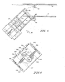
- Fig. 1 is a perspective view, partially cut away, of the invention;
- Fig. 2 is a side view, partially cut away, of the invention;
- Fig. 3 is a cross-sectional view of the invention, taken along lines 3-3 of Fig. 1;
- Fig. 4 is a cross-sectional view of the invention taken along lines 4-4 of Fig. 3;
- Fig. 5 is a partial plan view of the invention illustrating the swing-away feature of the exit conveyor;
- Fig. 6 is a side view of the invention showing the moving head and associated parts;
- Fig. 7 is a schematic representation of the press when the eccentric is at top dead center;
- Fig. 8 is a schematic representation of the press when the eccentric is 90° past top dead center;
- Fig. 9 is a schematic representation of the press when the eccentric is at bottom dead center (180° past top dead center);
- Fig. 10 is a schematic representation of the press when the eccentric is 270° past top dead center; and
- Fig. 11 is a cross-sectional view, similar to Fig. 3, of another embodiment of the invention.
- Referring now to Figs. 1-3, a
press 10 includes a frame 11 having abase 12, anupstanding wall 14 at one end of the base, and anupstanding wall 16 near the middle of the base '12. Thewalls base 12 are preferably constructed of rather substantial hot-rolled plate in order to withstand the pressures exerted upon them by the press components supported on them, and the forces exerted by thepress 10 in operation. Upstandingwall 14 further includes anopening 17 through which an operator can gain access to thepressing area 25. - Contiguous with
wall 16 ishousing 18 which includes a hingedly mounteddoor 19 having ahandle 20 and latch (not shown) which enable the user to gain access to the inside of thehousing 18 for servicing, but which protect the components inside thehousing 18 when thedoor 19 is closed. A free-standingcontrol panel 21 which communicates with thepress 10 throughumbilicals 22, 24 contains a plurality of controls through which the operator controls the actions of the press and adjusts such variables as stroke rate and dwell time, counters by which the operator keeps track ofpress 10 production, and microprocessors which are in communication with various components of the press. The microprocessors receive input from the various components and direct commands to various components based upon the operator's requests and the input received from the various components. A compressed air source (not shown) provides air to the press to operate and actuate the parts of thepress 10 which are air-driven or actuated. - Between the
upstanding walls press 10 is thepressing area 25 whereinblanks 26 are formed intocontainers 28.Precut blanks 26 are stacked onto anentrance conveyor 30 where they are individually moved into thepressing area 25, and then removed by, and stacked on, anexit conveyor 32.Entrance conveyor 30 andexit conveyor 32 are both movable to enable an operator to gain access to thepressing area 25 when servicing components therein.Entrance conveyor 30 is pulled upwardly and released downwardly bycables 36 and is guided byrollers 37 alongtracks 34.Cables 36 are pulled overpulleys 40 in order to move theentrance conveyor 30 with a force in the same direction as thetracks 34 run. Thecables 36 are actuated bypneumatic pistons 38.Adjustable levelers 39 are threadably engaged into the lower extremities oftracks 34. Thelevelers 39 are inserted into thetracks 34 to halt downward movement of theentrance conveyor 30 during times when theentrance conveyor 30 is being lowered into the operating position. The operator can adjust thelevelers 39 to ensure that when theentrance conveyor 30 is lowered into its operating position, it will be in vertical alignment with feedingchute 43. Fig 1 shows theentrance conveyor 30 in a partially raised position, and Fig. 2 shows theconveyor 30 in a lowered operating position. Theentrance conveyor 30 further includesupstanding guide rods 42 which serve to position theblanks 26 for feeding them into thepressing area 25 and also serves to maintain theblanks 26 in a neat stack. The position ofguide rods 42 is laterally and longitudinally adjustable in order to accommodate different-sized blanks 26. Theblanks 26 are moved individually into thepressing area 25 by the action ofpickups entrance conveyor 30 to serve as an intermediate blank 26 stop between the stack and thepressing area 25. The inclined angle of theentrance conveyor 30 allows theblanks 26 to fall into thepressing area 25 under the influence of gravity. Theblanks 26 which are formed by this embodiment ofpress 10 are precut and, if necessary, prescored. - As best shown in Figs. 1, 2, and 5,
exit conveyor 32 is hingedly mounted onhinge 48 which allows theconveyor 32 to be swung aside and thus provide an operator or serviceman with easy access into thepressing area 25. Ametallic plate 50 andmagnet 52 serve to secure theexit conveyor 32 in place when thepress 10 is not being serviced.Exit conveyor 32 further includes a pair ofconveyor belts 54 for moving the formedcontainers 28 to the end of the conveyor,pickups containers 28, and guiderods 60 for maintaining the formedcontainers 28 in a neat stack. The position ofguide rods 60 is laterally and longitudinally adjustable. - A product marker (not shown) is also included for marking a formed
container 28 after a predetermined number ofcontainers 28 have been made by the machine. The marking of a selectedcontainer 28 enables the operator to remove a predetermined number of formedcontainers 28 fromexit conveyor 32. - Referring now to Figs. 1 and 4, an
electric motor 62 includesoutput shaft 64 andoutput shaft 65, each of which turns apulley motor 62 is preferably at least 3 hp if driving a single press, and more powerful if driving multiple presses.Pulley 66 turns abelt 70 which partially surrounds the outer surface offlywheel 72, thereby rotatingflywheel 72 in the same direction aspulley 66.Pulley 68 rotatespulley 74 via abelt 78. The rotation ofpulley 68 in turn rotatesjackshaft 80 which, throughpulley 82 and belt 84, rotatesflywheel 86 ofadjacent press 88. Several other presses can be run in a line throughcommon jackshaft 80. The exposed portion ofjackshaft 80 betweenadjacent presses Press 88 is also provided with a control panel (not shown) similar to controlpanel 20 so that presses 10, 88 can be individually controlled, thereby allowing the operator to form different containers on presses operated off thecommon jackshaft 80. - Air
tube disk clutch 90 is secured toflywheel 86 so that the driving elements of the clutch 90 rotate coaxially with theflywheel 86.Clutch 90 is a preferably multiple plate clutch which is air-actuated viahose 92 which is rotatably mounted in the clutch 90 byconnector 94. This allows theclutch housing 96 to rotate while permitting theair hose 92 to remain stationary.Clutch housing 96 is secured toflywheel 86 by a plurality ofbolts 98. In the clutch 90 shown in Fig. 4, the clutch is engaged to theshaft 100 by pumping air under pressure into theair bladder 102, causing thebladder 102 to expand againstpressure plate 104. The movement ofpressure plate 104 forces the drivingdisks 106 into frictional engagement with the drivenplates 108 which are coupled to the drivenshaft 100. - Preferably, release springs (not shown) act to bias the driving
disks 106 out of engagement with the drivenplates 108 to minimize friction and contact between the drivingdisks 106 and drivenplates 108 when the clutch 90 is disengaged from theshaft 100. - The clutch 90 is biased to be normally disengaged from
shaft 100, and engages theshaft 100 only upon command.Shaft 100 is journaled onbearings bolts 114 to the insides ofwalls shaft 100 must be strong enough to support the weight exerted upon theshaft 100 by the clutch 90,flywheel 86, and other components. Thebearings bolts 114 must be strong enough to support theshaft 100 and the components supported by the shaft. -
Brake 115 is mounted to the outer surface ofwall 14 and is positioned proximate toshaft 100 to engageshaft 100.Brake 115 is spring-biased to be normally in engagement withshaft 100. Thebrake 115 includes an air release which, when applied, has sufficient strength to release thebrake 115 from its spring-biased engagement withshaft 100, thereby allowingshaft 100 to rotate freely. Thebrake 115 engagesshaft 100 when thepress 10 is not running, and at any time during operation of thepress 10 when the clutch 90 is disengaged from theshaft 100. Thebrake 115 is only released from engagement with theshaft 100 when the clutch 90 is engaged to theshaft 100.Press 10 will operate and will formcontainers 28, however, without the need of abrake 115. - Collared onto the
shaft 100 ispinion gear 116 which rotates withshaft 100 and meshes withspur gear 118.Spur gear 118 is collared upon input shaft 120 of a rotary transducer 122. Rotary transducer 122 is in communication with thecontrol panel 21 to inform thecontrol panel 21 of the rotational position of theshaft 100. As will be discussed below, the rotational position of theshaft 100 is directly translatable into the vertical position of theupper die 124. The rotary transducer 122 is thereby capable of informing thecontrol panel 21 of the vertical position of theupper die 124. - Referring now to Figs. 1, 3, 4, and 6, an eccentric 126 is collared onto the
shaft 100 through anopening 128 in the eccentric 126. The eccentric 126 is generally circular in shape.Opening 128 is offset from the center of the eccentric 126, thereby causing the diameter of the rotational path of eccentric 126 to be larger than the diameter of the eccentric 126. The eccentric 126 maintains its relative rotational position upon theshaft 100 by the insertion of a key 130 into correspondingopenings shaft 100 and eccentric 126, respectively. - The eccentric 126 rotates coaxially with the
shaft 100 inblock 136. The exterior ofblock 136 is substantially rectangular in shape, having exterior length and width dimensions which are approximately equal to each other.Block 136 contains a generallycircular opening 137, sized to slidably receive eccentric 126, and within which eccentric 126 rotates, imparting an eccentric path of travel to block 136, which results in reciprocating movement ofhead 138, within which block 136 is slidably contained. Theblock 136 is approximately as thick as eccentric 126.Head 138 includesside plates 140, 142,bottom plate 144,top plate 145,front plate 146, andrear plate 148.Side plates 140, 142 each include oblong-shaped openings 150 having their longest dimension in a direction parallel toarrow 152, shown in Fig. 2. The oblong-shaped openings 150 are provided in theside plates 140, 142 to provide clearance for theshaft 100 as the head travels in the directions indicated byarrow 152.Top plate 145 includes aninlet port 154 forlubricant line 156 and anoutlet port 158 forlubricant line 160 through which lubricant is circulated in the area between the inner surfaces of thehead 138 and the outer surfaces of theblock 136, and also in the area between the inner surface of theblock 136 and outer surface of the eccentric 126. -
Front plate 146 andrear plate 148 include V-shapedtongues grooves longitudinal bars arrow 152. Greasegrooves 153 are provided on V-shapedtongues tongues grooves tongues grooves Longitudinal bars planar cross members Planar cross members walls bolts 178. - Attached to
bottom plate 144 is die mountingplate 180, to which theupper die 124 is removably secured bybolts 182. Preferably, mountingplate 180 is of a universal type which will fit most or all of the dies 124 commonly used in the industry. - The
upper portion 183 ofupper die 124 can be equipped with heating elements (not shown) which serve to heat theupper die 124 and thereby quicken the formation offlat blanks 26 into formedcontainers 28.Upper die 124 includes air jets (not shown) which prevent the formedcontainers 28 from sticking to theupper die 124 after being pressed thereby. - Lower die 184 is mounted onto floating
base 186 bybolts 187. Lower die 184 illustrated in Figs. 1 and 3 is a telescoping die. Floatingbase 186 may be equipped with heating elements (not shown) to facilitate formation ofcontainers 28. Mounted to lower die 184 are a pair ofupstanding stops 185 which are sized and positioned to stop a blank 26 from sliding past thelower die 184, but to allow a formed container to slide therethrough. - The width of a formed
container 28 having raised portions is generally narrower than the flattened blank 26 from which it is formed, thereby allowing a formedcontainer 28 to slide through an opening through which a blank 26 would not pass. - Floating
base 186 is slidably mounted onsupport rods 188 tostationary base 190, such that position of the floatingbase 186 is vertically movable. Interposed between floatingbase 186 andstationary base 190 isair cushion 200 upon which the floatingbase 186 rests and which preferably is constructed out of a thick pliable rubber which is strong enough to withstand the pressure exerted on it by the floatingbase 186 and lower die 184 through the action of theupper die 124. -
Air cushion 200 also serves to counteract the force of gravity by biasing floatingbase 186 away fromstationary base 190. When a heating element is used in either theupper die 124,lower die 184, or floatingbase 186, an insulatingsheet 202 should be interposed between the floatingbase 186 and theair cushion 200. The insulatingsheet 202 helps to retard premature cracking and drying of the rubber inair cushion 200, and aids in preventing rupture ofair cushion 200 caused by the rubber in theair cushion 200 becoming melted due to the heat of the floatingbase 186. - Feeding
chute 43 andexit chute 204 are mounted ontolower die 184 and are vertically movable therewith.Entrance chute 206 andexit chute 208 are stationarily mounted to one or both ofupstanding walls chute 43 and removingchute 204 can be lengthened to captureblanks 26 directly from theentrance conveyor 30 in the case of the feedingchute 43, and to deliver formedcontainers 28 directly to theexit conveyor 32 in the case of the removingchute 204. Anopening 172 is provided inupstanding wall 14 to enable the operator to gain access to thepressing area 25 to change the upper and lower dies 124, 184. - Another embodiment of the instant invention is shown in Fig. 11 wherein
press 210 is adapted for cutting and forming sheet material. In this embodiment, entrance conveyor 33,pulley 40,pneumatic pistons 38, tracks 34,cables 36,rollers 37,levelers 39, and associated parts are eliminated.Entrance chute 206 and feedingchute 43 are modified. -
Press 210 is adapted to receive material from asheet material source 212 such asmaterial roll 214 which is rotatably mounted upon unwindstand 216 byaxle 218. Thesheet material source 212 produces a continuous sheet ofmaterial 220 which is fed into frame 11 ofpress 210.Press 210 includes a cutting means 222 for cutting sheet material and advancingmeans 223 for advancing sheet material into the frame 11, and transfer means 224 for transferring sheet material between the cutting means 222 and formingmeans - Guide means 226 includes
rollers 227, 228 andpaper guide 230. Preferably,paper guide 230 is constructed of a substantially planar steel plate having a pair of upstanding flanges (not shown) at either side of the plate to provide lateral guidance forsheet material 220 entering into frame 11. Decurling means 232 includes a pair ofdecurling rollers arm 236 which is pivotally connected to frame 11 to permit selective adjustment of thedecurling rollers decurling rollers sheet material 220. -
Drive rollers gear motor 240 having a clutch (not shown). The clutch serves to enable the user to pull material through therollers press 210. A pair of freely rotatingpulleys continuous sheet material 220.Pulley 242 also serves to positionsheet material 220 prior to placement ofsheet material 220 adjacent the cutting means 222. A loop-formingmeans 243 is provided which includeselectric eye control 244. Enough space is left betweendrive rollers pulley 241 to allow for an excess ofsheet material 220 therebetween. - Cutting means 222 includes a cutting die 245 having a band-
like blade 246 which is disposed in a groove (not shown) in cuttingdie 245. The groove (not shown) and band-like blade 246 are shaped to conform to the shape which the blank 26 is to take after cutting and prior to forming. Cutting die 245 is securedly attached tobase 248 bybolts 250.Base 248 is securedly attached totop plate 145 ofhead 138. Steel rule cuttingdie plate 252 is stationarily mounted to frame 11 to provide a surface against which band-like blade 246 can cutsheet material 220. - Transfer means 224 includes a second set of
pull rollers die plate 252 so as to pull waste sheet material in an arcuate path. Second pullrollers gear motor 256 having a clutch brake mechanism (not shown). The clutch enables the user to pullmaterial 220 through therollers material 220 on cutting means 222 when thematerial 220 is being cut. - A pair of cut-off
knives second pull rollers waste sheet material 220 pulled throughrollers blank conveyor 260 is provided for moving separated blanks laterally.Blank conveyor 260 includes anendless belt 262 which is mounted by a pair ofrollers Roller 264 is driven by the output shaft of a gear motor (not shown) which is mounted to the frame. -
Blank slide 267 is provided for moving the blank downwardly into a position adjacent formingdie Blank slide 267 is preferably constructed of sheet metal.Entrance chute 270 is connected to frame 11 for receiving blanks fed throughblank slide 264 and feeding them onto feedingchute 272. Feedingchute 272 is mounted ontolower die 184 and includes an intermediate stop means 274 such as pneumatically controlledintermediate stop cylinder 276 for placing a blank in a holding position before the blank is moved to a position adjacent forming dies 124, 184. - Referring now to Figs. 7-10, schematic representations are shown depicting the relative positions of the
cross members brake 306,head 308, block 310, eccentric 312,shaft 314,upper die 316,lower die 318,air cushion 320,stationary base 322 for thelower die 318, cutting die 324 and cuttingdie plate 326 during a typical pressing cycle of thepress 328.Press 328 is represented as being similar topress 210. The described cycle is similar forpress 10, except for the inclusion of the sheet material cutting. - Referring now to Fig. 7, the
press 328 is shown with theshaft 314 and eccentric 312 at top dead center, which is the press' 328 initial rest position for changing upper 316 and lower 318 dies or the like. This is also the position wherein cutting die 324 and cuttingdie plate 326 are engaged to cut sheet material into a formable element. During the normal pressing cycle whenflywheel 72 is rotating, theshaft 314, eccentric 312, block 310, andhead 308 do not remain in this raised position but rather continue through this position in a smooth cycle. When initially in this position, the clutch 304 is disengaged from theshaft 314 and thebrake 306 is spring-biased to engageshaft 314, thereby preventingshaft 314 from rotating. Eccentric 312 raises theblock 310 to the uppermost vertical position in its cycle while laterally centering theblock 310 in thehead 308. This results in thehead 308 being in its uppermost raised position, and cutting die 324 being engaged with cuttingdie plate 326. -
Upper die 316 is fully disengaged fromlower die 318, andair cushion 320, upon which lower die 318 rests, is in a relatively uncompressed state, having only the weight of thelower die 318 acting to compress it. It is during the press's quarter cycle shown in Fig. 7 when a blank 26 would normally be inserted betweenupper die 316 andlower die 318. - When the
press 328 receives a command to begin a pressing cycle, clutch 304 is air-actuated to engageshaft 314, and thereby begin rotatingshaft 314. Simultaneously,brake 306 is air-actuated to releaseshaft 314 and thereby permit it to rotate in response to the engagement ofshaft 314 byclutch 304. - Referring now to Fig. 8, the
press 328 is shown at a position in its pressing cycle wherein theshaft 314 and eccentric 312 are 90° past top dead center. At this position, the clutch 304 remains engaged toshaft 314 and thebrake 306 remains released therefrom. The rotational position of the eccentric 312 in theblock 310 has caused theblock 310 to move laterally and downwardly. As thehead 308 is not laterally movable, theblock 310 moves laterally within thehead 308, without affecting the lateral positioning of thehead 308. Thehead 308 is vertically movable, and will so move in response to vertical movement ofblock 310. As shown in Fig. 8, thehead 308 has responded to the downwardly vertical movement ofblock 310, by also moving vertically downward. Being mounted uponhead 308, theupper die 316 and cutting die 324 also move downwardly. The relative positions of the cutting dieplate 326,lower die 318, andair cushion 320 remain unchanged. - Approximately 150° past top dead center, the clutch 304 begins its disengagement from
shaft 314, simultaneously with thebrake 306 commencing its engagement withshaft 314. - Referring now to Fig. 9, the
press 328 is shown in its pressing cycle at a point at which theshaft 314 and eccentric 312 are at bottom dead center (180° past top dead center). The clutch 304 is disengaged fromshaft 314 andbrake 306 is engaged to theshaft 314.Shaft 314 is at rest, and all movement of the eccentric 312, block 310,head 308, cuttingdie 324,upper die 316,lower die 318, andair cushion 320 is stopped. - The above-mentioned components will remain stopped in this position until such time as
clutch 304 is air-actuated to engageshaft 314, and thebrake 306 is air-actuated to disengageshaft 314. The period of time during which the components remain in this position is the dwell time. As stated above, the dwell time is selectively variable, and is controllable by the operator through thecontrol panel 21. - From its position in Fig. 7 to its position in Fig. 8, the rotation of the eccentric 312 has laterally moved the
block 310 to a centered position withinhead 308 and has vertically movedblock 310 downwardly to its lowermost vertical position in the cycle. The vertically downward movement ofblock 310 has movedhead 308 downwardly to its lowermost vertical position in the cycle. Downward movement ofupper die 316 has caused it to engage lower die 318, moving lower die 318 in a downwardly vertical direction. The downward movement oflower die 318 has causedair cushion 320 to become compressed betweenlower die 318 andstationary base 322. The expansive forces exerted by theair cushion 320 to counteract the compressive forces exerted upon theair cushion 320 by thehead 308,upper die 316, and lower die 318 maintain thelower die 318 in intimate engagement withupper die 316. Further, these above-mentioned forces aid in providing the press force necessary to form the blank 26 into a formedcontainer 28. The vertical compressibility ofair cushion 320 also allows theupper die 316 to engage thelower die 318 at a point in the cycle prior to bottom dead center, and to release thelower die 318 at a point in the cycle past bottom dead center. - At the end of the selected dwell time,
clutch 304 is air-actuated to re-engage theshaft 314 simultaneously with the air actuation ofbrake 306 to releaseshaft 314, thereby causing eccentric 312 to rotate. Referring now to Fig. 10, thepress 328 is shown at its point in the pressing cycle wherein theshaft 314 and eccentric 312 are 270° past top dead center. At this stage, the clutch 304 is engaged to rotate theshaft 314, and thebrake 306 is actuated to release theshaft 314. The rotational movement of eccentric 312 inblock 310 has laterally moved theblock 310 within the head, and has moved thehead 308 vertically upward through the vertical, upward movement ofblock 310.Upper die 316 is pulled out of engagement withlower die 318, andair cushion 320 is released from its compressed state. Normally, at some point during this stage of the cycle, air will be applied to the formedcontainer 28 to release it from engagement with the dies 316, 318. Also, advancing means 223 will have advanced the continuous sheet ofmaterial 220 into a position wherein the cutting means 222 can cut another blank. Thereafter, thepress 328 continues through the various illustrated stages of the cycle until it again comes to dwell at the bottom dead center position shown in Fig. 9. - Referring now to Figs. 1-3, in operation of the press,
unformed blanks 26, which are stacked onentrance conveyor 30, are individually removed from the stack bypickups Blank 26 slides down theentrance conveyor 30 and onto theentrance chute 206, then ontolower die 184 mounted to feedingchute 43, and finally comes to rest onlower die 184. The blank 26 is stopped at, and held onto, lower die 184 by stops 189. The blank 26 is then formed into acontainer 28 through the engagement oflower die 184 andupper die 124. When dies 124, 184 are released from engagement, air is blown against the formedcontainer 28 to prevent it from sticking toupper die 124. Through the action of gravity, aided by blown air to reduce the friction of the container as it slides down the removingchute 204 andexit chute 208, thereby speeding its travel to theexit conveyor 32, the formedcontainer 28 slides down thelower die 184 mounted removingchute 204, onto theexit chute 208, and finally ontoexit conveyor 32. Once onexit conveyor 32,container 28 is moved byconveyor belts 54 toward the end ofexit conveyor 32. At an appropriate point,pickups container 28 onto the bottom of a stack ofcontainers 28. - The operation of
press 210, shown in Fig. 11, will now be described. Thedrive rollers continuous sheet material 220 frommaterial roll 214 which is rotatably mounted upon unwindstand 216. Thecontinuous sheet material 220 is pulled upwardly overroller 228, laterally positioned bypaper guide 230, and pulled over roller 227. Thesheet material 220 is pulled betweendecurling rollers sheet material 220 by its winding onmaterial roll 214. - Second pull
rollers continuous sheet material 220 aroundpulleys die plate 252. An excess of material is left betweenpull rollers 238 andpulley 241. The size of the loop is controlled byelectric eye 244 which is in communication withcontrol panel 21. Should thecontinous sheet material 220 break the light beam emitted byelectric eye control 244, the press can be made to shut down to prevent damage tosheet material 220 and thecontainers 28 formed by thepress 210. Generally, pullrollers 238 pull in a generally continuous manner, whereassecond pull roller Pull rollers plate 252, and then stop the advance of thesheet material 220 to allow the cutting die 245 and steel rule dieplate 252 to cut a stationary target. This ensures that thesheet material 220 will be accurately and sharply cut, and not torn due to movement of thesheet material 220, whileblade 246 is in contact therewith. - The movement of
pull rollers second pull rollers head 138 andshaft 100 to ensure thatsufficient material 220 is available to enable the cutting means 222 to cut a fully sized blank 26, and to ensure that thematerial 220 is stationary when theblade 246 of cutting die 245 is engaged with steel rule dieplate 252. - After the
sheet material 220 is cut by cuttingmeans 222, the waste sheet material is pulled in a severe, arcuate manner betweenpull rollers means 222. Waste sheet material is then cut by cuttingknives press 210 near a vacuum hose (not shown) which removes the sheet materials particles from the area of thepress 210. The blank cut by cuttingmeans 222 is conveyed laterally byblank conveyor 260 and is delivered toblank slide 267.Blank slide 267 transports the blank laterally and downwardly, delivering it toentrance chute 270. The blank travels fromentrance chute 270 onto feedingchute 43. Disposed on feedingchute 43 is an intermediate stop means 274 which holds the blank in a holding position before feeding it into the area adjacent to cutting dies 124, 184. The forming step ofpress 210 is similar to that ofpress 10 shown in Figs. 1-4, and described above. - Although the invention has been described in detail with reference to certain preferred embodiments and specific examples, variations and modifications exist within the scope and spirit of the invention as described and as defined in the following claims.
Claims (16)
Applications Claiming Priority (4)
| Application Number | Priority Date | Filing Date | Title |
|---|---|---|---|
| US06/382,716 US4435143A (en) | 1982-05-27 | 1982-05-27 | Small blank feeder and tray former |
| US382716 | 1982-05-27 | ||
| US458348 | 1983-01-17 | ||
| US06/458,348 US4497620A (en) | 1982-05-27 | 1983-01-17 | Small press for forming sheet material |
Publications (3)
| Publication Number | Publication Date |
|---|---|
| EP0095680A2 true EP0095680A2 (en) | 1983-12-07 |
| EP0095680A3 EP0095680A3 (en) | 1984-08-29 |
| EP0095680B1 EP0095680B1 (en) | 1987-05-06 |
Family
ID=27009875
Family Applications (1)
| Application Number | Title | Priority Date | Filing Date |
|---|---|---|---|
| EP83105014A Expired EP0095680B1 (en) | 1982-05-27 | 1983-05-20 | Press for forming sheet material |
Country Status (4)
| Country | Link |
|---|---|
| US (1) | US4497620A (en) |
| EP (1) | EP0095680B1 (en) |
| CA (1) | CA1200130A (en) |
| DE (1) | DE3371308D1 (en) |
Cited By (1)
| Publication number | Priority date | Publication date | Assignee | Title |
|---|---|---|---|---|
| WO2009056674A1 (en) * | 2007-10-29 | 2009-05-07 | Ari Kinnunen | Device for crushing cans/bottles or similar objects |
Families Citing this family (10)
| Publication number | Priority date | Publication date | Assignee | Title |
|---|---|---|---|---|
| US5904643A (en) * | 1997-06-13 | 1999-05-18 | Tenneco Packaging | Tray-forming and apparatus |
| JP2001524403A (en) | 1997-12-03 | 2001-12-04 | ピアレス マシーン アンド トゥール コーポレイション | Pressed paper cut-in press die |
| US20070032361A1 (en) * | 2005-08-05 | 2007-02-08 | Venuti Alan R | Multiple stage web material processor |
| MY143512A (en) * | 2005-08-29 | 2011-05-31 | Gcg Holdings Ltd | Eccentric rotary stamping apparatus and method of forming moving sheet metal |
| US20150209992A1 (en) * | 2014-01-24 | 2015-07-30 | Automated Packaging Systems, Inc. | Plastic mesh and methods of forming the same |
| US9782817B2 (en) * | 2014-06-10 | 2017-10-10 | Getter Dunn Technologies, Llc | System and method of varying dwell time in a honeycomb plate press |
| CN110315738A (en) * | 2019-08-06 | 2019-10-11 | 江琴 | A kind of sizing of flexible material and trimming machine |
| US11938699B2 (en) | 2021-07-07 | 2024-03-26 | Brown Llc | Methods and systems for producing pressware |
| US11945670B2 (en) | 2021-07-07 | 2024-04-02 | Brown Llc | Methods and systems for producing pressware |
| US11919270B2 (en) | 2021-07-07 | 2024-03-05 | Brown Llc | Methods and systems for producing pressware |
Citations (8)
| Publication number | Priority date | Publication date | Assignee | Title |
|---|---|---|---|---|
| DE111036C (en) * | ||||
| DE80128C (en) * | 1900-01-01 | |||
| DE744331C (en) * | 1942-04-30 | 1944-01-17 | Wilhelm Brocksieper Fa | Press for bags, especially for gluing the multi-layer bottom |
| GB559698A (en) * | 1942-08-26 | 1944-03-01 | William Frank Golding | Improvements in or relating to mechanically operated presses |
| DE875139C (en) * | 1950-01-22 | 1953-04-30 | S Wilhelm Nattermueller Fa | Eccentric press |
| US3064559A (en) * | 1959-11-19 | 1962-11-20 | Ross B Treer | Press |
| FR2208748A1 (en) * | 1972-08-26 | 1974-06-28 | Schuler Gmbh L | |
| US4158539A (en) * | 1978-05-10 | 1979-06-19 | Leesona Corporation | Thermoforming machine with variable mold closed cycle |
Family Cites Families (33)
| Publication number | Priority date | Publication date | Assignee | Title |
|---|---|---|---|---|
| NL3141C (en) * | ||||
| US1037844A (en) * | 1908-10-02 | 1912-09-10 | Benjamin Adriance | Machine for forming sheet-metal articles. |
| US1038860A (en) * | 1908-12-19 | 1912-09-17 | M D Knowlton Co | Sheet-cutting machine. |
| US1162302A (en) * | 1915-04-29 | 1915-11-30 | William G Moffet | Automatic stacker. |
| US1207390A (en) * | 1915-11-15 | 1916-12-05 | Republic Stamping & Enameling Company | Feeding device for presses. |
| US1661248A (en) * | 1925-12-10 | 1928-03-06 | Vortex Mfg Co | Dish-forming machine |
| US1780012A (en) * | 1929-10-05 | 1930-10-28 | Sanitary Products Corp Of Amer | Machine for forming articles from sheet materials |
| US1962872A (en) * | 1933-07-01 | 1934-06-12 | Ontario Mfg Company | Automatic feed for blanks |
| US2015798A (en) * | 1933-09-27 | 1935-10-01 | Procter & Gamble | Method of and apparatus for handling and stamping plastic material |
| US2243206A (en) * | 1940-05-09 | 1941-05-27 | Edward H Hall | Clutch controlled die press or the like |
| US2275758A (en) * | 1940-06-15 | 1942-03-10 | Gen Motors Corp | Control mechanism for presses |
| US2632643A (en) * | 1946-11-05 | 1953-03-24 | Eastman Kodak Co | Apparatus for handling and photographically copying documents |
| US2891644A (en) * | 1954-09-29 | 1959-06-23 | Davis George | Clutch or brake mechanism |
| US3002222A (en) * | 1958-06-30 | 1961-10-03 | Ex Cell O Corp | Decurling apparatus |
| GB935285A (en) * | 1958-09-09 | 1963-08-28 | Hoechst Ag | Improvements in or relating to the production of plastic containers |
| US3193881A (en) * | 1961-09-06 | 1965-07-13 | Comet Ind | Automatic plastic forming and trimming machine |
| US3096692A (en) * | 1962-03-16 | 1963-07-09 | Fmc Corp | Box making machine |
| US3355073A (en) * | 1962-09-24 | 1967-11-28 | Jack L Moore | Methods of and apparatus for producing shaped products |
| DE1577951B2 (en) * | 1965-07-30 | 1976-08-05 | L. Schüler GmbH, 7320 Göppingen | INFEED AND DISCHARGE DEVICE ON A PRESS |
| US3477270A (en) * | 1966-12-22 | 1969-11-11 | Schuler Gmbh L | Coin press |
| GB1224314A (en) * | 1967-03-09 | 1971-03-10 | Wykeham Farrance Engineering L | Improvements relating to oedometers |
| US3659993A (en) * | 1969-10-24 | 1972-05-02 | Packaging Ind Inc | Apparatus for forming containers |
| US3948162A (en) * | 1971-03-05 | 1976-04-06 | Aida Engineering Limited | Press line system |
| US3754705A (en) * | 1972-07-05 | 1973-08-28 | Littell F Machine Co | Double cam driven feed roll |
| US4057380A (en) * | 1974-04-16 | 1977-11-08 | Machida Shigyo Co., Ltd. | Tray-like container and a method of and an apparatus for manufacturing the container |
| SE401340B (en) * | 1974-06-28 | 1978-05-02 | Tetra Pak Dev | DEVICE FOR FORMING A PACKAGING MATERIAL PATH IN A PACKAGING MACHINE |
| DE2452050C2 (en) * | 1974-11-22 | 1984-05-03 | M.A.N. Maschinenfabrik Augsburg-Nürnberg AG, 8900 Augsburg | Device for registering sheets in sheet-fed rotary printing machines |
| US4056186A (en) * | 1975-04-21 | 1977-11-01 | Morgan Construction Company | Coil handling apparatus and system |
| GB1538476A (en) * | 1977-05-17 | 1979-01-17 | Massey Ltd B | Forging press |
| DE2743058C2 (en) * | 1977-09-24 | 1979-12-20 | Adolf Illig Maschinenbau Gmbh & Co, 7100 Heilbronn | Method for controlling the movement of a forming table of an automatic thermoforming machine and automatic thermoforming machine, which is driven by a cam |
| DE2822178C2 (en) * | 1978-05-20 | 1981-05-07 | Herbert Kannegiesser Gmbh + Co, 4973 Vlotho | Device for the production of moldings from foamable plastics |
| US4255382A (en) * | 1980-03-20 | 1981-03-10 | Leesona Corporation | Thermoforming machine with automatically mechanically operated web stripping element |
| US4355530A (en) * | 1980-12-02 | 1982-10-26 | Chen Ho L | Punching machine for making different products at the same step |
-
1983
- 1983-01-17 US US06/458,348 patent/US4497620A/en not_active Expired - Lifetime
- 1983-05-20 EP EP83105014A patent/EP0095680B1/en not_active Expired
- 1983-05-20 DE DE8383105014T patent/DE3371308D1/en not_active Expired
- 1983-05-25 CA CA000428792A patent/CA1200130A/en not_active Expired
Patent Citations (8)
| Publication number | Priority date | Publication date | Assignee | Title |
|---|---|---|---|---|
| DE111036C (en) * | ||||
| DE80128C (en) * | 1900-01-01 | |||
| DE744331C (en) * | 1942-04-30 | 1944-01-17 | Wilhelm Brocksieper Fa | Press for bags, especially for gluing the multi-layer bottom |
| GB559698A (en) * | 1942-08-26 | 1944-03-01 | William Frank Golding | Improvements in or relating to mechanically operated presses |
| DE875139C (en) * | 1950-01-22 | 1953-04-30 | S Wilhelm Nattermueller Fa | Eccentric press |
| US3064559A (en) * | 1959-11-19 | 1962-11-20 | Ross B Treer | Press |
| FR2208748A1 (en) * | 1972-08-26 | 1974-06-28 | Schuler Gmbh L | |
| US4158539A (en) * | 1978-05-10 | 1979-06-19 | Leesona Corporation | Thermoforming machine with variable mold closed cycle |
Cited By (1)
| Publication number | Priority date | Publication date | Assignee | Title |
|---|---|---|---|---|
| WO2009056674A1 (en) * | 2007-10-29 | 2009-05-07 | Ari Kinnunen | Device for crushing cans/bottles or similar objects |
Also Published As
| Publication number | Publication date |
|---|---|
| US4497620A (en) | 1985-02-05 |
| EP0095680B1 (en) | 1987-05-06 |
| CA1200130A (en) | 1986-02-04 |
| EP0095680A3 (en) | 1984-08-29 |
| DE3371308D1 (en) | 1987-06-11 |
Similar Documents
| Publication | Publication Date | Title |
|---|---|---|
| US4435143A (en) | Small blank feeder and tray former | |
| US4497620A (en) | Small press for forming sheet material | |
| JPH06270295A (en) | Box blank forming device and scouring/slotting assembly | |
| US4523500A (en) | Method and apparatus for cutting continuous corrugated member | |
| JPS60255414A (en) | Thermoforming device | |
| JPS58185240A (en) | System manufacturing paper product from paper roll | |
| US3583295A (en) | Carton erection machine | |
| JP3364263B2 (en) | Method for separating sheets of paper stacked in a bundle and apparatus for implementing the method | |
| US4831716A (en) | Inserting insulating material into electric motor stators | |
| JP2552994B2 (en) | Punching method and punching device | |
| US4416196A (en) | Tying machine | |
| CN110000314B (en) | Big flat nail former | |
| US4267009A (en) | Apparatus for assembling closures | |
| US4196663A (en) | Hold-down acceleration device | |
| US2576096A (en) | Molding and wrapping machine | |
| CN211055517U (en) | Indentation mechanism of vertical packaging machine | |
| CA1140384A (en) | Apparatus for assembling closures and control system therefor | |
| SU1551451A1 (en) | Automatic complex for stamping parts from strip and band material | |
| CN115446182B (en) | Hardware stamping device convenient to fix hardware | |
| CN218197196U (en) | Improved paper box forming equipment | |
| JPH07136997A (en) | Punching device | |
| CN214137536U (en) | Crease device is used in carton processing | |
| CN210100886U (en) | Fillet pressing device | |
| US1231693A (en) | Soap-press. | |
| US3709415A (en) | Automatic stripping machine |
Legal Events
| Date | Code | Title | Description |
|---|---|---|---|
| PUAI | Public reference made under article 153(3) epc to a published international application that has entered the european phase |
Free format text: ORIGINAL CODE: 0009012 |
|
| AK | Designated contracting states |
Designated state(s): BE CH DE FR GB IT LI LU NL SE |
|
| RBV | Designated contracting states (corrected) |
Designated state(s): BE CH DE FR GB IT LI LU NL SE |
|
| PUAL | Search report despatched |
Free format text: ORIGINAL CODE: 0009013 |
|
| AK | Designated contracting states |
Designated state(s): BE CH DE FR GB IT LI LU NL SE |
|
| 17P | Request for examination filed |
Effective date: 19840822 |
|
| GRAA | (expected) grant |
Free format text: ORIGINAL CODE: 0009210 |
|
| AK | Designated contracting states |
Kind code of ref document: B1 Designated state(s): BE CH DE FR GB IT LI LU NL SE |
|
| PG25 | Lapsed in a contracting state [announced via postgrant information from national office to epo] |
Ref country code: NL Effective date: 19870506 Ref country code: LI Effective date: 19870506 Ref country code: IT Free format text: LAPSE BECAUSE OF FAILURE TO SUBMIT A TRANSLATION OF THE DESCRIPTION OR TO PAY THE FEE WITHIN THE PRESCRIBED TIME-LIMIT;WARNING: LAPSES OF ITALIAN PATENTS WITH EFFECTIVE DATE BEFORE 2007 MAY HAVE OCCURRED AT ANY TIME BEFORE 2007. THE CORRECT EFFECTIVE DATE MAY BE DIFFERENT FROM THE ONE RECORDED. Effective date: 19870506 Ref country code: CH Effective date: 19870506 Ref country code: BE Effective date: 19870506 |
|
| PG25 | Lapsed in a contracting state [announced via postgrant information from national office to epo] |
Ref country code: LU Free format text: LAPSE BECAUSE OF NON-PAYMENT OF DUE FEES Effective date: 19870531 |
|
| REF | Corresponds to: |
Ref document number: 3371308 Country of ref document: DE Date of ref document: 19870611 |
|
| ET | Fr: translation filed | ||
| REG | Reference to a national code |
Ref country code: CH Ref legal event code: PL |
|
| NLV1 | Nl: lapsed or annulled due to failure to fulfill the requirements of art. 29p and 29m of the patents act | ||
| PLBE | No opposition filed within time limit |
Free format text: ORIGINAL CODE: 0009261 |
|
| STAA | Information on the status of an ep patent application or granted ep patent |
Free format text: STATUS: NO OPPOSITION FILED WITHIN TIME LIMIT |
|
| 26N | No opposition filed | ||
| PGFP | Annual fee paid to national office [announced via postgrant information from national office to epo] |
Ref country code: SE Payment date: 19910503 Year of fee payment: 9 |
|
| PGFP | Annual fee paid to national office [announced via postgrant information from national office to epo] |
Ref country code: DE Payment date: 19910510 Year of fee payment: 9 |
|
| PGFP | Annual fee paid to national office [announced via postgrant information from national office to epo] |
Ref country code: GB Payment date: 19910513 Year of fee payment: 9 |
|
| PGFP | Annual fee paid to national office [announced via postgrant information from national office to epo] |
Ref country code: FR Payment date: 19910531 Year of fee payment: 9 |
|
| PG25 | Lapsed in a contracting state [announced via postgrant information from national office to epo] |
Ref country code: GB Effective date: 19920520 |
|
| PG25 | Lapsed in a contracting state [announced via postgrant information from national office to epo] |
Ref country code: SE Effective date: 19920521 |
|
| GBPC | Gb: european patent ceased through non-payment of renewal fee |
Effective date: 19920520 |
|
| PG25 | Lapsed in a contracting state [announced via postgrant information from national office to epo] |
Ref country code: FR Effective date: 19930129 |
|
| PG25 | Lapsed in a contracting state [announced via postgrant information from national office to epo] |
Ref country code: DE Effective date: 19930202 |
|
| REG | Reference to a national code |
Ref country code: FR Ref legal event code: ST |
|
| EUG | Se: european patent has lapsed |
Ref document number: 83105014.1 Effective date: 19921204 |