EP0094867B1 - Method and device for the acquisition and treatment of written data - Google Patents
Method and device for the acquisition and treatment of written data Download PDFInfo
- Publication number
- EP0094867B1 EP0094867B1 EP83400903A EP83400903A EP0094867B1 EP 0094867 B1 EP0094867 B1 EP 0094867B1 EP 83400903 A EP83400903 A EP 83400903A EP 83400903 A EP83400903 A EP 83400903A EP 0094867 B1 EP0094867 B1 EP 0094867B1
- Authority
- EP
- European Patent Office
- Prior art keywords
- trace
- computer
- code
- individual
- detection
- Prior art date
- Legal status (The legal status is an assumption and is not a legal conclusion. Google has not performed a legal analysis and makes no representation as to the accuracy of the status listed.)
- Expired
Links
Images

Classifications
-
- G—PHYSICS
- G06—COMPUTING; CALCULATING OR COUNTING
- G06V—IMAGE OR VIDEO RECOGNITION OR UNDERSTANDING
- G06V10/00—Arrangements for image or video recognition or understanding
- G06V10/10—Image acquisition
- G06V10/17—Image acquisition using hand-held instruments
-
- G—PHYSICS
- G06—COMPUTING; CALCULATING OR COUNTING
- G06V—IMAGE OR VIDEO RECOGNITION OR UNDERSTANDING
- G06V10/00—Arrangements for image or video recognition or understanding
- G06V10/10—Image acquisition
- G06V10/12—Details of acquisition arrangements; Constructional details thereof
Definitions
- US-A-4 241 409 which describes a device providing for deducing a trace by capturing the displacements of mechanical parts and translating these movements into electrical signals (column 4, lines 57 to 59).
- This device also requires the detection of forces and the measurement of angles (column 4 line 59 to column 5 line 2). It is clear that this device leaves practically no freedom to the writer who is forced to conform his writing to a standard writing to which the device compares the plot. This one, moreover, could not be visible since we detect movements and not the concrete result of these movements.
- the problems of contrast, in particular, between the surface receiving the trace and the trace itself are entirely foreign to this invention.
- EP-AO 035 036 which describes a read head using optical character detection means, but these means provide for apprehending all of each drawn character as a finished whole, in the manner of an image or photograph (page 4 lines 15 to 17 and 24 to 26).
- the optical means moreover, take account of the directions in which the various components of the characters are traced and each character is broken down into segments, that is to say into lines having an origin and an arrival, ie two points.
- the device includes a program stored in memory and character recognition supposes the comparison between the stored algorithms and the information collected during the plotting (page 7, lines 5 to 7 and 8 to 25).
- the problem which the invention proposes to solve is therefore different from that to which we have hitherto focused since we do not come up against the difficulty of the global recognition of a sign whose exact morphology and dimensions are different from one writer to another.
- the sign is analyzed optically as it is created, that is to say that one attaches to the course of the tracing instrument more than the overall image finished and constituting a definitive whole.
- the subject of the invention is a method of reading of the direct optical detection type for entering and processing data plotted in clear by a writing instrument known per se on any medium but the appearance of which is contrasted. with respect to the course, characterized in that the significance of the course is determined as long as this course develops by noting certain characteristic points of the course determined by the optical intersection of this course and at least one of several lines of detection and this as many times as an intersection occurs, even if the interested part of the trace has already been in intersection with at least one detection line, that a code known as “individual invariable to each detection line is assigned , that the individual code of a line is recorded each time an optical intersection occurs with it, that a sequence or sequence of individual codes is memorized until its end which is determined by an interruption of the layout for a time greater than a pre-established duration, that a so-called “global” code is assigned to each possible sequence, independently of the order in which the layout is developed, that each of the successive global codes is introduced in a computer of any known type
- the invention also relates to a device for implementing a reading method of the direct optical detection type for entering and processing data plotted in clear on any medium but whose appearance is contrasted with respect to the layout, comprising an optical detection assembly, a transcoder, a calculator, a result delivery member, such as a display dial and a source of electrical energy, characterized on the one hand in that the assembly detection comprises a frame whose so-called “active elements are arranged in radial lines and are connected to the transcoder and, on the other hand, in that an erasable type memory, a timer and a clock are placed at the input of the calculator, in addition and independently of the usual memories specific to this calculator, said detection assembly at least being placed in a pen body carrying a tracing instrument known per se disposed at the virtual center common to the radial lines.
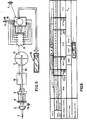
- the device has the general shape of a pen comprising a body 1, one end of which ends with a writing tip 2 of the ball-type while the the other carries two contacts 3 whose usefulness will be specified later.
- the body 1 can receive a cap 4 provided with a clip 5 and which can cooperate with the body 1 either by one end or by the other according to any known means.
- the actual end of the body 1 where the writing tip 2 is located is provided with a lens 6 pierced in its center to provide a passage for the tip 2.
- the cap 4 has a removable end 4a closing off a housing in which a battery 7 of any known type must be placed, the contacts 7a of which are intended to bear on the contacts 3 of the body 1 when the cap 4 having been removed from its position tip protection 2 (fig. 1) was placed on the other end of body 1 (fig. 2).
- the device is then powered and can operate as will be described now.
- a frame 8 In the axis of the lens 6 and in its immediate vicinity, there is a frame 8, the details of which will be given below with reference to FIGS. 3 and 4 and which is electronically connected to a transcoder 9 constituted here by a photo-detector such as a photocell. This is connected electronically to a comparator or analyzer 10 of any type known per se, connected to a clock timer 11 associated with an erasable memory 12.
- This assembly is placed and connected to the input of a computer of any known type comprising a decoder 13 and a memory microprocessor 14, all supplied from the battery 7.
- a small lighting lamp 15 is associated with the lens 6 in order to project a light ray onto the support A on which the user draws by means of the tip 2.
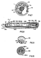
- the frame 8 consists of a solid disc 8a in which are formed very fine slots 8b which radiate from a virtual center which is that of the disc 8a.
- the central part of the disc 8a is occupied by a circular passage 8c intended for the tracing tip 2.
- each slot 8b has been assigned a mark assigned clockwise from A to H and from 1 to 8, so that each diametral slot is designated by the combination of a letter and a number: A-1, C-3, E-5, etc.
- FIG. 4 shows seven phases of the drawing of the figure "8 and, for clarity of the drawing, the frame 8 and the slots 8b are shown diagrammatically by simple lines.
- Phase I corresponds to the starting point, that is to say that no segment of the route is yet visible.
- Phase II represents the beginning of the first loop that the writer traces here from left to right.
- Phase III represents the end of the first loop supposed to extend from the summit to the crossing center.
- Phase IV represents the route of half of the lower loop.
- Phase V represents the continuation of the route just before the crossing point.
- Phase VI represents roughly half the route of the last upper loop.
- Phase VII represents the end of the track and, here, this end is a little above the starting point as the writer wanted.
- Each trace must, however, be recognized in order to be able to be processed in the computer so that we must, first, assign an individual invariable code to each slot, then then constitute standard sequences, or sequences, to each of which affects a global code.
- timer 11 which notes a total interruption in tracing when the tip is lifted from the support A to write the next digit or symbol for a predetermined time.
- sequences are determined not only by the presence of the individual codes but also by the order in which these individual codes appear.
- Each sequence being formed is temporarily stored in memory 12, then is then introduced into decoder 13 of the computer.
- This operation is exactly equivalent to pressing a keyboard key for a conventional calculating machine using a calculator of the same type.
- the body 1 comprises a dial 16 of any known type, and in particular with liquid crystal, on which the result is displayed.
- FIG. 6 constitutes a diagram developing the various operations carried out.
- the memory 12 records the individual codes corresponding to the slots 8b and which correspond to the “geometric code of FIG. 3 and that for the digit“ 0 ”.
- a is at least equal to a predetermined time which is represented in figure 6 by the column x constituting the origin of the arrow F1 signifying that this time interval has the effect of transforming the sequence of individual binary code into a global binary code signifying the digit "0".
- the time interval represented by column x1 is determined by the timer 11 timer and it is therefore at the end of this time interval that the global coding and erasing of the memory 12 ready takes place, thus, to receive the following sequence.
- the order can either be provided by means of a trace such as "C” or "CE” according to international standardization.
- buttons 17 and 18 can also provide on the body 1, two buttons 17 and 18 corresponding to these conventional functions.
- the walls 20 and 21 can, in particular, be made in the form of shells of synthetic material connected by spacers (not shown) to form a whole integral with the components and which can be removed and put in place easily.
- the tracing tip 200 and its cartridge 200a are placed laterally, which allows the entire interior space of the body 100 to be used to house the various electronic components.
- the geometry of the optical detection assembly must be a little different and it can be seen that the axis a of the lens 600 makes with the axis p of the writing tip 200 an angle ⁇ .
- this particular shape of the device makes it possible to symmetrically locate, on either side of the writing tip 200, two lighting members 24 and 25 intended, as we have said with regard to the member 15, to illuminate the plane A on which the user is tracing, in view to increase the contrast between this plane A and the tracing itself.
- the tracing point partly extends over the corresponding screen 800, as can be seen in FIG. 10.
- the invention also allows other uses which consist of any combination of a plot and a calculator.
- Sockets 26 and 27 can be provided to connect the portable device according to the invention to a large computer by means of a light cable (not shown).
- the frame can, as we have said, be constituted by a solid disc notched with slots or, on the contrary, be constituted by an opaque network leaving areas through which the light passes.
- instrument to be traced can be of any known type: ballpoint, pen, felt, etc.
Abstract
Description
On connaît déjà de nombreux procédés et dispositifs permettant la saisie et le traitement de données tracées en clair comme, par exemple les brevets suivants :
- Le brevet US-A-4 241 409 qui concerne un dispositif de poche présentant la forme d'un stylo et muni, sur un côté, d'un écran d'affichage. Par des moyens mécaniques qui font l'objet de ce brevet, on traduit les déplacements du dispositif en informations électroniques fournies au calculateur dont la fonction est d'identifier électroniquement les signes tracés à la main. L'écran d'affichage permet à l'usager de contrôler l'exactitude de l'identification électronique.
- Patent US-A-4 241 409 which relates to a pocket device having the shape of a pen and provided, on one side, with a display screen. By mechanical means which are the subject of this patent, the movements of the device are translated into electronic information supplied to the computer, the function of which is to electronically identify the signs drawn by hand. The display screen allows the user to check the accuracy of the electronic identification.
Le brevet US-A-4 005 400 qui décrit un calculateur auquel les informations sont données non pas en actionnant des touches correspondant individuellement à des caractères significatifs mais en formant à la main le code complexe correspondant à ces caractères.The patent US-A-4 005 400 which describes a computer to which the information is given not by actuating keys corresponding individually to significant characters but by hand forming the complex code corresponding to these characters.
Il faut rappeler qu'avec les calculateurs classiques, les caractères sont « préfabriqués » et l'on doit avoir une touche par caractère. Il en résulte un rangement des touches en clavier qui prend beaucoup de place.It should be remembered that with conventional computers, the characters are "prefabricated" and one must have one key per character. This results in a storage of the keys on the keyboard which takes up a lot of space.
Selon l'invention de ce brevet, on remplace le clavier par une sorte de matrice que l'on actionne avec un stylet conducteur spécial pour « fabriquer chaque caractère par éléments successifs. La contrepartie du gain de place est une perte de temps et une complication des manipulations.According to the invention of this patent, the keyboard is replaced by a sort of matrix which is actuated with a special conductive stylus to "make each character by successive elements. The counterpart to saving space is a waste of time and a complication of handling.
Le brevet US-A-4 241 409 qui décrit un dispositif prévoyant de déduire un tracé par la captation des déplacements de pièces mécaniques et la traduction de ces mouvements en signaux électriques (colonne 4, lignes 57 à 59). Ce dispositif nécessite aussi la détection de forces et la mesure d'angles (colonne 4 ligne 59 à colonne 5 ligne 2). Il est clair que ce dispositif ne laisse pratiquement aucune liberté au scripteur qui est contraint de conformer son écriture à une écriture étalon à laquelle le dispositif compare le tracé. Celui-ci, d'ailleurs, pourrait n'être pas visible puisque l'on détecte des mouvements et non le résultat concret de ces mouvements. Les problèmes de contraste, notamment, entre la surface recevant le tracé et le tracé lui-même sont tout à fait étrangers à cette invention.US-A-4 241 409 which describes a device providing for deducing a trace by capturing the displacements of mechanical parts and translating these movements into electrical signals (column 4, lines 57 to 59). This device also requires the detection of forces and the measurement of angles (column 4 line 59 to
La demande EP-A-O 035 036 qui décrit une tête de lecture mettant en oeuvre des moyens de détection optique de caractères, mais ces moyens prévoient d'appréhender l'ensemble de chaque caractère tracé comme un tout fini, à la manière d'une image ou photographie (page 4 lignes 15 à 17 et 24 à 26). Les moyens optiques, en outre, tiennent compte des directions selon lesquelles sont tracés les différents composants des caractères et l'on décompose chaque caractère en segments, c'est-à-dire en lignes ayant une origine et une arrivée, soit deux points. Enfin, le dispositif comporte un programme mis en mémoire et la reconnaissance des caractères suppose la comparaison entre les algorithmes mémorisés et les informations recueillies lors du tracé (page 7, lignes 5 à 7 et 8 à 25).EP-AO 035 036 which describes a read head using optical character detection means, but these means provide for apprehending all of each drawn character as a finished whole, in the manner of an image or photograph (page 4
Les difficultés d'une reconnaissance globale d'un signe sont si importantes que l'on a pratiquement renoncé aux tracés à la main, de sorte que l'on doit toujours passer par l'intermédiaire d'un codage et/ou d'une normalisation des signes à reconnaître, ce qui est le cas, par exemple, des chiffres d'identification des chèques bancaires.The difficulties of a global recognition of a sign are so great that one has practically given up the drawing by hand, so that one must always pass by means of a coding and / or a standardization of the signs to be recognized, which is the case, for example, with identification numbers for bank checks.
La présente invention est tout à fait différente de ces procédés et dispositifs connus car elle se caractérise par un système de lecture optique directe, sans aucun intermédiaire mécanique, incorporé à l'instrument et délivré de toute contrainte extérieure telle que support d'écriture spécial, écriture conventionnelle ou standardisée, etc.The present invention is entirely different from these known methods and devices because it is characterized by a direct optical reading system, without any mechanical intermediary, incorporated into the instrument and delivered from any external constraint such as a special writing medium, conventional or standardized writing, etc.
Le problème que se propose de résoudre l'invention est donc différent de celui auquel on s'est attaché jusqu'à maintenant puisqu'on ne se heurte pas à la difficulté de la reconnaissance globale d'un signe dont la morphologie exacte et les dimensions sont différentes d'un scripteur à l'autre.The problem which the invention proposes to solve is therefore different from that to which we have hitherto focused since we do not come up against the difficulty of the global recognition of a sign whose exact morphology and dimensions are different from one writer to another.
Selon l'invention, au contraire, on analyse optiquement le signe au fur et à mesure qu'il est créé, c'est-à-dire que l'on s'attache au parcours de l'instrument de traçage plus qu'à l'image globale terminée et constituant un tout définitif.According to the invention, on the contrary, the sign is analyzed optically as it is created, that is to say that one attaches to the course of the tracing instrument more than the overall image finished and constituting a definitive whole.
A cette fin, l'invention a pour objet un procédé de lecture du type à détection optique directe pour la saisie et le traitement de données tracées en clair par un instrument à écrire connu en soi sur un support quelconque mais dont l'aspect est contrasté par rapport au tracé, caractérisé en ce que l'on détermine la signification du tracé tant que ce parcours se développe en relevant certains points caractéristiques du tracé déterminés par l'intersection optique de ce tracé et d'au moins l'une de plusieurs lignes de détection et cela autant de fois qu'une intersection se produit, même si la partie intéressée du tracé a déjà été en intersection avec au moins une ligne de détection, que l'on affecte un code dit « individuel invariable à chaque ligne de détection, que l'on enregistre le code individuel d'une ligne chaque fois que se produit avec elle une intersection optique, que l'on mémorise une suite ou séquence de codes individuels jusqu'à sa fin qui est déterminée par une interruption du tracé pendant un temps supérieur à une durée pré-établie, que l'on affecte un code dit « global à chaque séquence possible, indépendamment de l'ordre dans lequel se développe le tracé, que l'on introduit chacun des codes globaux successifs dans un calculateur de tout type connu à la fin de leur durée et, enfin, que l'on traduit en clair, visuellement et/ou phonétiquement, le résultat du traitement des codes globaux effectué par le calculateur au moyen d'un programme interne non modifiable commandé par certaines séquences correspondant à des signes intelligibles du tracé.To this end, the subject of the invention is a method of reading of the direct optical detection type for entering and processing data plotted in clear by a writing instrument known per se on any medium but the appearance of which is contrasted. with respect to the course, characterized in that the significance of the course is determined as long as this course develops by noting certain characteristic points of the course determined by the optical intersection of this course and at least one of several lines of detection and this as many times as an intersection occurs, even if the interested part of the trace has already been in intersection with at least one detection line, that a code known as “individual invariable to each detection line is assigned , that the individual code of a line is recorded each time an optical intersection occurs with it, that a sequence or sequence of individual codes is memorized until its end which is determined by an interruption of the layout for a time greater than a pre-established duration, that a so-called “global” code is assigned to each possible sequence, independently of the order in which the layout is developed, that each of the successive global codes is introduced in a computer of any known type at the end of their duration and, finally, which is translated in clear, visually and / or phonetically, the result of the processing of the global codes carried out by the computer by means of an internal program not modifiable controlled by certain sequences corresponding to intelligible signs of the layout.
Selon d'autres caractéristiques de ce procédé :
- on relève les points caractéristiques du parcours en établissant une trame dont les éléments sensibles sont disposés en lignes radiales et sont codés, et en déplaçant cette trame selon un mouvement lié à celui de l'instrument à écrire ;
- on associe l'instrument à écrire et la trame selon une position relative invariable, la partie dudit instrument étant en coïncidence avec un élément neutre de la trame constituant, éventuellement, une origine des éléments codés.
- the characteristic points of the route are noted by establishing a frame whose sensitive elements are arranged in radial lines and are coded, and by moving this frame according to a movement linked to that of the writing instrument;
- the writing instrument and the frame are associated in an invariable relative position, the part of said instrument being in coincidence with a neutral element of the frame constituting, possibly, an origin of the coded elements.
L'invention a également pour objet un dispositif pour la mise en oeuvre d'un procédé de lecture du type à détection optique directe pour la saisie et le traitement de données tracées en clair sur un support quelconque mais dont l'aspect est contrasté par rapport au tracé, comprenant un ensemble de détection optique, un transcodeur, un calculateur, un organe de délivrance de résultats, tel qu'un cadran d'affichage et une source d'énergie électrique, caractérisé d'une part en ce que l'ensemble de détection comprend une trame dont les éléments dits « actifs sont disposés en lignes radiales et sont reliés au transcodeur et, d'autre part, en ce qu'une mémoire de type effaçable, un temporisateur et une horloge sont placés à l'entrée du calculateur, en plus et indépendamment des mémoires habituelles propres à ce calculateur, ledit ensemble de détection au moins étant placé dans un corps de stylo portant un instrument à tracer connu en soi disposé au centre virtuel commun aux lignes radiales.The invention also relates to a device for implementing a reading method of the direct optical detection type for entering and processing data plotted in clear on any medium but whose appearance is contrasted with respect to the layout, comprising an optical detection assembly, a transcoder, a calculator, a result delivery member, such as a display dial and a source of electrical energy, characterized on the one hand in that the assembly detection comprises a frame whose so-called “active elements are arranged in radial lines and are connected to the transcoder and, on the other hand, in that an erasable type memory, a timer and a clock are placed at the input of the calculator, in addition and independently of the usual memories specific to this calculator, said detection assembly at least being placed in a pen body carrying a tracing instrument known per se disposed at the virtual center common to the radial lines.
Selon d'autres caractéristiques de ce dispositif :
- il est tout entier placé dans un corps de stylo qui comprend un cadran d'affichage latéral ;
- le corps de stylo est associé à un capuchon amovible pouvant être placé soit sur l'une, soit sur l'autre des deux extrémités dudit corps, celui-ci comprenant, sur son extrémité opposée à celle qui porte l'instrument à tracer, des contacts pour au moins une pile placée dans le fond du capuchon amovible ;
- l'ensemble de détection comprend une lentille d'extrémité, la trame optiquement co-axiale à la lentille, le transcodeur constitué par un photodétecteur et, de préférence, une source lumineuse devant éclairer le plan de traçage afin d'accroître le contraste entre ledit plan et le tracé.
- it is entirely placed in a pen body which includes a lateral display dial;
- the pen body is associated with a removable cap which can be placed either on one or on the other of the two ends of said body, the latter comprising, on its end opposite to that which carries the instrument to be traced, contacts for at least one battery placed in the bottom of the removable cap;
- the detection assembly comprises an end lens, the frame optically co-axial with the lens, the transcoder constituted by a photodetector and, preferably, a light source which must illuminate the tracing plane in order to increase the contrast between said plot plan and layout.
L'invention sera mieux comprise par la description détaillée ci-après faite en référence au dessin annexé. Bien entendu, la description et le dessin ne sont donnés qu'à titre d'exemple indicatif et non limitatif.
- La figure 1 est une vue schématique avec coupe partielle montrant un dispositif conforme à invention réalisé sous la forme d'un stylo.
- La figure 2 est une vue schématique en perspective du même dispositif en cours d'utilisation.
- La figure 3 est une vue schématique d'une trame équipant un dispositif conforme aux figures 1 et 2 ci-dessus.
- La figure 4 montre schématiquement sept étapes du tracé du chiffre « 8 •.
- La figure 5 est un schéma général d'un dispositif conforme à l'invention.
- La figure 6 est un tableau schématisant le déroulement d'une opération arithmétique.
- La figure 7 est une vue en coupe transversale d'un dispositif conforme à l'invention réalisé sous la forme d'un stylo.
- La figure 8 est une vue schématique montrant un dispositif conforme à l'invention réalisé sous forme d'un stylo et dont l'instrument de traçage est décentré.
- La figure 9 est une vue schématique de face de ce même dispositif.
- La figure 10 est une vue schématique d'une trame équipant un stylo conforme aux figures 8 et 9.
- Figure 1 is a schematic view in partial section showing a device according to the invention made in the form of a pen.
- Figure 2 is a schematic perspective view of the same device in use.
- Figure 3 is a schematic view of a frame fitted to a device according to Figures 1 and 2 above.
- Figure 4 schematically shows seven steps in plotting the number "8 •.
- Figure 5 is a general diagram of a device according to the invention.
- FIG. 6 is a table diagramming the course of an arithmetic operation.
- Figure 7 is a cross-sectional view of a device according to the invention produced in the form of a pen.
- Figure 8 is a schematic view showing a device according to the invention made in the form of a pen and whose tracing instrument is off-center.
- Figure 9 is a schematic front view of the same device.
- FIG. 10 is a schematic view of a frame fitted to a pen according to FIGS. 8 and 9.
En se reportant au dessin, on voit un mode de réalisation de l'invention selon lequel le dispositif a la forme générale d'un stylo comprenant un corps 1 dont une extrémité se termine par une pointe à écrire 2 du genre à bille tandis que l'autre porte deux contacts 3 dont l'utilité sera précisée plus loin.Referring to the drawing, we see an embodiment of the invention according to which the device has the general shape of a pen comprising a
Le corps 1 peut recevoir un capuchon 4 muni d'une agrafe 5 et pouvant coopérer avec le corps 1 soit par une extrémité soit par l'autre selon tout moyen connu.The
La pointe à écrire 2 et son tube à encre capillaire 2a sont placés dans l'axe du corps 1 et y sont assujettis de manière amovible comme cela est connu en soi.The
L'extrémité proprement dite du corps 1 où se trouve la pointe à écrire 2, est munie d'une lentille 6 percée en son centre pour ménager un passage à la pointe 2.The actual end of the
Le capuchon 4 comporte une extrémité amovible 4a obturant un logement dans lequel doit être placée une pile 7 de tout type connu dont les contacts 7a sont destinés à s'appuyer sur les contacts 3 du corps 1 lorsque le capuchon 4 ayant été retiré de sa position de protection de la pointe 2 (fig. 1 ) a été placé sur l'autre extrémité du corps 1 (fig. 2).The cap 4 has a
Le dispositif est alors alimenté et peut fonctionner comme on va le décrire maintenant.The device is then powered and can operate as will be described now.
Dans l'axe de la lentille 6 et à son voisinage immédiat, se trouve une trame 8 dont le détail sera donné plus loin en regard des figures 3 et 4 et qui est reliée électroniquement à un transcodeur 9 constitué ici d'un photo-détecteur tel qu'une cellule photo-électrique. Celle-ci est reliée électroniquement à un comparateur ou analyseur 10 de tout type connu en soi, relié à un temporisateur à horloge 11 associé à une mémoire effaçable 12.In the axis of the
Cet ensemble est placé et relié à l'entrée d'un calculateur de tout type connu comprenant un décodeur 13 et un microprocesseur à mémoire 14, le tout alimenté à partir de la pile 7.This assembly is placed and connected to the input of a computer of any known type comprising a
Enfin, une petite lampe d'éclairage 15 est associée à la lentille 6 afin de projeter un rayon lumineux sur le support A sur lequel l'usager effectue un tracé au moyen de la pointe 2.Finally, a
Avant de décrire le fonctionnement complet de ce dispositif, on va maintenant décrire la trame 8 en regard de la figure 3.Before describing the complete operation of this device, we will now describe the frame 8 with reference to FIG. 3.
La trame 8 est constituée d'un disque plein 8a dans lequel sont ménagées des fentes très fines 8b qui rayonnent à partir d'un centre virtuel qui est celui du disque 8a. La partie centrale du disque 8a est occupée par un passage circulaire 8c destiné à la pointe traçante 2.The frame 8 consists of a
Pour la clarté de l'exposé, on a affecté à chaque fente 8b un repère attribué dans le sens des aiguilles d'une montre de A à H et de 1 à 8, de sorte que chaque fente diamétrale est désignée par la combinaison d'une lettre et d'un chiffre : A-1, C-3, E-5, etc.For the sake of clarity, each slot 8b has been assigned a mark assigned clockwise from A to H and from 1 to 8, so that each diametral slot is designated by the combination of a letter and a number: A-1, C-3, E-5, etc.
Naturellement, dans la réalité, ces repères n'ont pas de signification et l'on utilise le code binaire pour identifier chaque fente diamétrale ou radiale.Of course, in reality, these markers have no meaning and we use the binary code to identify each diametral or radial slot.
En effet, il peut s'avérer utile soit de prévoir un nombre de fentes plus grand que celui représenté ici et qui est de huit fentes diamétrales ou seize radiales, soit de différencier les deux fentes radiales placées l'une dans le prolongement de l'autre et constituant une fente diamétrale ce qui reviendrait, ici, à appeler 0 l'extrémité de chaque fente située près du centre. Dans ce cas, les lignes seraient désignées ainsi : A-0, B-0, C-0, etc. 1-0, 2-0, 3-0, etc.Indeed, it may prove useful either to provide a larger number of slots than that shown here and which is eight diametrical or sixteen radial slots, or to differentiate the two radial slots placed one in the extension of the other and constituting a diametrical slot which would amount, here, to calling 0 the end of each slot located near the center. In this case, the lines would be designated as follows: A-0, B-0, C-0, etc. 1-0, 2-0, 3-0, etc.
Les composants électroniques que l'on a décrit ci-dessus sont organisés de telle manière que l'ensemble est en position neutre, bien que l'ensemble soit alimenté, lorsque le maximum de lumière passe à travers les fentes 8b.The electronic components that have been described above are organized in such a way that the assembly is in neutral position, although the assembly is supplied, when the maximum of light passes through the slots 8b.
Lorsque l'utilisateur trace sur le support A des chiffres ou des signes, il déplace l'ensemble du dispositif et, notamment, la trame 8 qui en est solidaire, de sorte qu'au fur et à mesure de son tracé, des segments de celui-ci se trouvent en regard des fentes 8b qui, ainsi obscurcies partiellement, influencent le transcodeur (ou photo-détecteur) 9, lequel transmet les impulsions optiques ainsi perçues à l'analyseur 10 qui déduit en code laquelle ou lesquelles fentes 8b se sont trouvées au moins une fois en coïncidence avec une partie du tracé.When the user traces numbers or signs on the support A, he moves the entire device and, in particular, the frame 8 which is integral with it, so that as it is traced, segments of these are located opposite the slots 8b which, thus partially obscured, influence the transcoder (or photo-detector) 9, which transmits the optical pulses thus perceived to the
Pour illustrer ces dispositions, on a représenté sur la figure 4 sept phases du tracé du chiffre « 8 ét, pour la clarté du dessin, on a schématisé la trame 8 et les fentes 8b par de simples traits.To illustrate these arrangements, FIG. 4 shows seven phases of the drawing of the figure "8 and, for clarity of the drawing, the frame 8 and the slots 8b are shown diagrammatically by simple lines.
La phase I correspond au point de départ, c'est-à-dire qu'aucun segment du tracé n'est encore visible.Phase I corresponds to the starting point, that is to say that no segment of the route is yet visible.
La phase Il représente le début de la première boucle que le scripteur trace ici de gauche à droite.Phase II represents the beginning of the first loop that the writer traces here from left to right.
La phase III représente la fin de la première boucle supposée s'étendre depuis le sommet jusqu'au centre de croisement.Phase III represents the end of the first loop supposed to extend from the summit to the crossing center.
La phase IV représente le tracé de la moitié de la boucle inférieure.Phase IV represents the route of half of the lower loop.
La phase V représente la suite du tracé juste avant le point de croisement.Phase V represents the continuation of the route just before the crossing point.
La phase VI représente à peu près la moitié du tracé de la dernière boucle supérieure.Phase VI represents roughly half the route of the last upper loop.
La phase VII représente la fin du tracé et, ici, cette fin se situe un peu au-dessus du point de départ car ainsi l'a voulu le scripteur.Phase VII represents the end of the track and, here, this end is a little above the starting point as the writer wanted.
Ici apparaît une caractéristique de l'invention, à savoir que l'on ne procède pas par analyse globale d'un tracé antérieurement effectué pour le comparer à un ou plusieurs tracés type constituant des échantillons mais, au contraire, on analyse un tracé au fur et à mesure qu'il est créé en retenant la coïncidence de ce tracé avec des lignes repères qui ici sont constituées par les fentes 8b.Here appears a characteristic of the invention, namely that one does not proceed by global analysis of a plot previously made to compare it with one or more standard plots constituting samples but, on the contrary, one analyzes a plot as and as it is created by retaining the coincidence of this layout with reference lines which here are constituted by the slots 8b.
Chaque tracé doit, néanmoins, être reconnu pour pouvoir être traité dans le calculateur de sorte que l'on doit, d'abord, affecter un code individuel invariable à chaque fente, puis ensuite constituer des suites types, ou séquences, à chacune desquelles on affecte un code global.Each trace must, however, be recognized in order to be able to be processed in the computer so that we must, first, assign an individual invariable code to each slot, then then constitute standard sequences, or sequences, to each of which affects a global code.
Pour déterminer ces séquences, on a utilisé un procédé statistique qui consiste à faire effectuer un même tracé par un assez grand nombre de personnes, à recueillir les codes individuels par branchement direct sur le transcodeur 9 puis à ne retenir de ces codes individuels que ceux qui sont communs à toutes les personnes.To determine these sequences, a statistical process was used which consists of having the same route carried out by a fairly large number of people, collecting the individual codes by direct connection to the
On a représenté ci-dessous trois exemples énoncés non pas en code binaire mais selon le code « géométrique utilisé pour la figure 3, et correspondant au tracé des dix chiffres de 1 à 0 :Three examples have been shown below, not in binary code but according to the “geometric code used for FIG. 3, and corresponding to the plotting of the ten digits from 1 to 0:


Après avoir dépouillé le résultat de plusieurs dizaines de ces tracés individuels, on en a tiré des codes communs, ce qui donne, par exemple, la sélection suivante :


Pour que le dispositif enregistre en code binaire les chiffres 1, 2, 3 etc., il faut déterminer chaque séquence correspondante et, par conséquent, déterminer la fin de la série des codes individuels symbolisés ici par les couples lettre - chiffre se rapportant aux fentes 8b.In order for the device to record the
C'est la fonction du temporisateur 11 qui constate une interruption totale de tracé lorsque la pointe est soulevée du support A pour écrire le chiffre ou le symbole suivant pendant un temps prédéterminé.It is the function of the
D'autre part, les séquences sont déterminées non seulement par la présence des codes individuels mais également par l'ordre dans lequel se présentent ces codes individuels.On the other hand, the sequences are determined not only by the presence of the individual codes but also by the order in which these individual codes appear.
Pour le chiffre 2 on a remarqué que celui-ci pouvait donner lieu soit à la série : A1 - B2 - E5 - D4 soit à la série : A1 - B2 - D4 - E5.For the
L'expérience pourra montrer, peut-être, d'autres alternatives et on en tiendra alors compte dans la programmation du dispositif, cette opération étant à la portée de l'homme de métier.Experience may show, perhaps, other alternatives and this will then be taken into account in the programming of the device, this operation being within the reach of the skilled person.
Chaque séquence en cours de constitution est mémorisée à titre provisoire dans la mémoire 12, puis est ensuite introduite dans le décodeur 13 du calculateur.Each sequence being formed is temporarily stored in
Cette opération équivaut exactement à la pression d'une touche de clavier pour une machine à calculer classique utilisant un calculateur de même type.This operation is exactly equivalent to pressing a keyboard key for a conventional calculating machine using a calculator of the same type.
Lorsqu'au lieu de tracer un chiffre, l'usager trace un signe, celui-ci est codé de la même manière puis est ensuite fourni au calculateur comme si l'utilisateur agissait sur une touche marquée de ce signe avec un clavier traditionnel.When, instead of drawing a number, the user draws a sign, it is coded in the same way and is then supplied to the computer as if the user were acting on a key marked with this sign with a traditional keyboard.
De la sorte, le calculateur travaille à partir des signes tracés comme s'il était commandé avec un clavier.In this way, the computer works from the traced signs as if it were controlled with a keyboard.
Il effectue donc les différentes opérations nécessaires avec les chiffres voulus et le résultat est demandé et obtenu lorsque l'utilisateur trace le signe «=» comme on l'a représenté sur la figure 2.It therefore performs the various operations necessary with the desired figures and the result is requested and obtained when the user traces the sign "=" as shown in FIG. 2.
Le corps 1 comporte un cadran 16 de tout type connu, et notamment à cristaux liquides, sur lequel s'affiche le résultat.The
On voit ainsi que grâce au procédé et au dispositif conformes à l'invention, il suffit d'écrire les chiffres et les différents signes possibles pour faire travailler le calculateur, puis de tracer le signe "_" pour obtenir immédiatement le résultat qui s'affiche sur le cadran 16.It can thus be seen that, thanks to the method and the device in accordance with the invention, it suffices to write the figures and the various possible signs to make the computer work, then to trace the sign "_" to immediately obtain the result which displayed on the
L'exemple représenté sur la figure 2 consiste à effectuer la multiplication de 0,2 par 6 et le résultat, c'est-à-dire 1,2 apparaît sur le cadran 16 dès que le signe "=" a été tracé.The example shown in FIG. 2 consists in multiplying 0.2 by 6 and the result, that is to say 1.2, appears on the
Cet exemple se retrouve sur la figure 6 qui constitue un diagramme développant les différentes opérations effectuées.This example is found in FIG. 6 which constitutes a diagram developing the various operations carried out.
Tout d'abord, après lecture optique et transduction en code binaire, la mémoire 12 enregistre les codes individuels correspondant aux fentes 8b et qui correspondent au code « géométrique de la figure 3 et cela pour le chiffre « 0 ».First of all, after optical reading and transduction in binary code, the
Après avoir tracé le chiffre « 0 », l'utilisateur lève la pointe traçante pour écrire la virgule et « l'espace entre « 0 » et « , a est au moins égal à un temps prédéterminé qui est figuré sur la figure 6 par la colonne x constituant l'origine de la flèche F1 signifiant que cet intervalle de temps a pour effet de transformer la séquence de code binaire individuel en un code binaire global signifiant le chiffre « 0».After having traced the figure "0", the user lifts the tracing point to write the decimal point and "the space between" 0 "and", a is at least equal to a predetermined time which is represented in figure 6 by the column x constituting the origin of the arrow F1 signifying that this time interval has the effect of transforming the sequence of individual binary code into a global binary code signifying the digit "0".
L'intervalle de temps figuré par la colonne x1 est déterminé par l'horloge du temporisateur 11 et c'est donc à la fin de cet intervalle de temps que se produit le codage global et l'effacement de la mémoire 12 prête, ainsi, à recevoir la séquence suivante.The time interval represented by column x1 is determined by the
La même série d'opérations : codage individuel, constatation de la fin de séquence, temporisation et codage global se reproduit pour chacun des signes et des chiffres tracés.The same series of operations: individual coding, observation of the end of the sequence, time delay and global coding is reproduced for each of the signs and numbers traced.
Ainsi, après « 0 se trouve le signe « , dont le code global est obtenu à la fin du temps x2 comme le montre la flèche F2.Thus, after "0 is the sign", whose global code is obtained at the end of time x2 as shown by arrow F2.
Ensuite se trouve formé de la même manière le code du chiffre « 2 •, puis l'espace de temps x3 correspondant à l'espace entre le chiffre « 2 et le signe « x •, puis le signe « x dont le code est formé à la fin du temps x4 selon la flèche F4, puis le chiffre « 6 à à la fin du temps x5 selon la flèche F5 puis le signe " = " qui commande le résultat codé comme le fait comprendre la flèche F6 et, instantanément, ce résultat codé commande le cadran 16, comme le symbolise la flèche F7, pour afficher le résultat en clair : « 1, 2".Then is found in the same way the code of the digit "2 •, then the time space x3 corresponding to the space between the digit" 2 and the sign "x •, then the sign" x whose code is formed at the end of time x4 according to arrow F4, then the number "6 at the end of time x5 according to arrow F5 then the sign" = "which controls the coded result as shown by arrow F6 and, instantly, this coded result controls
Naturellement, selon le calculateur choisi, on peut effectuer des calculs plus ou moins compliqués depuis les quatre opérations arithmétiques simples jusqu'à des fonctions plus complexes comme cela est bien connu.Naturally, depending on the computer chosen, one can perform more or less complicated calculations from the four simple arithmetic operations to more complex functions as is well known.
Pour obtenir l'effacement du cadran 16 et obtenir une nouvelle disponibilité du calculateur, on peut soit prévoir la commande au moyen d'un tracé tel que «C» ou « CE » selon une normalisation internationale.To obtain the erasure of the
On peut, également, prévoir sur le corps 1, deux boutons 17 et 18 correspondant à ces fonctions classiques.One can also provide on the
On a également le choix, pour l'obtention du résultat des opérations, entre le codage particulier du signe « = comme cela a été décrit plus haut et une touche spéciale 19 dite «touche de résultatThere is also a choice, for obtaining the result of the operations, between the particular coding of the sign "= as described above and a special key 19 called" result key
Pour que tous les composants électroniques soient bien protégés, notamment lorsque l'on place et que l'on retire la pointe traçante 2 et la cartouche 2a, on peut prévoir comme cela se voit sur les figures 2 et 7 deux parois courbes concentriques 20 et 21 entre lesquelles sont localisés les composants désignés par la référence générale 22 sur la figure 7.So that all the electronic components are well protected, in particular when the
Les parois 20 et 21 peuvent, notamment, être réalisées sous forme de coquilles en matière synthétique reliées par des entretoises d'écartement (non représentées) pour former un tout solidaire des composants et pouvant être retiré et mis en place aisément.The
Sur la figure 8, on a représenté schématiquement un autre mode de réalisation selon lequel l'instrument à tracer n'est pas co-axial au corps du stylo.In Figure 8, there is shown schematically another embodiment according to which the instrument to be traced is not coaxial with the body of the pen.
Avec ce mode de réalisation, la pointe à tracer 200 et sa cartouche 200a sont placées latéralement, ce qui permet d'utiliser tout l'espace intérieur du corps 100 pour y loger les différents composants électroniques.With this embodiment, the
Par analogie avec les références des figures précédentes, on a utilisé les mêmes chiffres mais dans l'ordre des centaines.By analogy with the references of the preceding figures, the same figures were used but in the order of hundreds.
Avec ces dispositions, la géométrie de l'ensemble de détection optique doit être un peu différente et l'on voit que l'axe a de la lentille 600 fait avec l'axe p de la pointe à écrire 200 un angle ω.With these provisions, the geometry of the optical detection assembly must be a little different and it can be seen that the axis a of the
Il est alors nécessaire de prévoir un renvoi des rayons lumineux, ce qui peut être obtenu au moyen d'un prisme 23.It is then necessary to provide a return of the light rays, which can be obtained by means of a
En se reportant à la figure 9, on voit que cette forme particulière du dispositif permet de situer symétriquement, de part et d'autre de la pointe à écrire 200, deux organes d'éclairage 24 et 25 destinés, comme on l'a dit à propos de l'organe 15, à éclairer le plan A sur lequel l'usager effectue son tracé, en vue d'accroître le contraste entre ce plan A et le tracé lui-même.Referring to FIG. 9, it can be seen that this particular shape of the device makes it possible to symmetrically locate, on either side of the
Avec un mode de réalisation de ce genre, la pointe traçante s'étend en partie sur la trame correspondante 800, ainsi que cela se voit sur la figure 10.With an embodiment of this kind, the tracing point partly extends over the
En effet, si l'on désire que la pointe 200 se trouve optiquement à l'aplomb du centre de la trame 800 alors que ces deux éléments ne sont pas concentriques, il faut nécessairement accepter de neutraliser un certain nombre de fentes 800b, ce qui est schématisé par le quartier 800d sur la figure 10.Indeed, if it is desired that the
Il peut s'avérer que ce montage n'ait pas un inconvénient rédhibitoire surtout si le nombre de fentes 800b est relativement grand et procure ainsi une plus grande précision assurant une discrimination des tracés des différents signes et chiffres sans devoir utiliser la partie inférieure de la trame 800.It may turn out that this arrangement does not have a prohibitive drawback, especially if the number of
On a choisi de décrire l'invention en relation avec le tracé de chiffres pour obtenir des opérations arithmétiques.We chose to describe the invention in relation to the plotting of numbers to obtain arithmetic operations.
Mais l'invention permet également d'autres usages qui consistent en une combinaison quelconque d'un tracé et d'un calculateur.However, the invention also allows other uses which consist of any combination of a plot and a calculator.
Ainsi, on peut utiliser un dispositif conforme à l'invention pour obtenir une conversion de longueurs en différentes échelles : en faisant parcourir une certaine distance à l'instrument à tracer sur un dessin, on obtient sur le cadran d'affichage une longueur correspondante dans une autre échelle ou en pieds et pouces à partir d'une longueur en centimètres, etc.Thus, it is possible to use a device in accordance with the invention to obtain a conversion of lengths into different scales: by making the instrument to be traced on a drawing travel a certain distance, a corresponding length is obtained on the display dial in another scale or in feet and inches from a length in centimeters, etc.
On peut également obtenir la lecture de notes de musique écrites sur une portée etc. On peut prévoir des prises 26 et 27 (figure 1) pour relier le dispositif portatif conforme à l'invention à un calculateur de grandes dimensions au moyen d'un câble léger (non représenté).You can also get music notes written on a staff etc.
On peut également, lorsqu'on désire utiliser un ordinateur ou une calculatrice de grandes dimensions, ne prévoir que l'ensemble de détection dans le corps 1 (éléments 10 à 12) tandis que tous les éléments dits « calculateurs sont dans l'installation fixe.It is also possible, when it is desired to use a computer or a large calculator, to provide only the detection assembly in the body 1 (
Lorsque l'on utilise la voie optique, la trame peut, comme on l'a dit, être constituée par un disque plein entaillé de fentes ou, au contraire, être constituée par un réseau opaque laissant subsister des quartiers par lesquels passe la lumière.When using the optical channel, the frame can, as we have said, be constituted by a solid disc notched with slots or, on the contrary, be constituted by an opaque network leaving areas through which the light passes.
Naturellement, l'instrument à tracer peut être de n'importe quel type connu : à bille, à plume, à feutre, etc.Of course, the instrument to be traced can be of any known type: ballpoint, pen, felt, etc.
Il peut également s'agir d'un outil procédant par enlèvement ou apport de matière et les informations obtenues peuvent être introduites dans un calculateur qui effectue non plus des opérations arithmétiques mais coopère avec un système d'asservissement ou exploite le résultat à toutes autres fins.It can also be a tool proceeding by removal or addition of material and the information obtained can be entered into a computer which no longer performs arithmetic operations but cooperates with a servo system or exploits the result for all other purposes .
Claims (7)
Priority Applications (1)
| Application Number | Priority Date | Filing Date | Title |
|---|---|---|---|
| AT83400903T ATE29608T1 (en) | 1982-05-18 | 1983-05-05 | METHOD AND DEVICE FOR ACQUISITION AND TREATMENT OF WRITTEN DATA. |
Applications Claiming Priority (2)
| Application Number | Priority Date | Filing Date | Title |
|---|---|---|---|
| FR8208634 | 1982-05-18 | ||
| FR8208634A FR2527362B1 (en) | 1982-05-18 | 1982-05-18 | METHOD AND DEVICE FOR INPUT AND PROCESSING OF CLEAR TRACKED DATA |
Publications (2)
| Publication Number | Publication Date |
|---|---|
| EP0094867A1 EP0094867A1 (en) | 1983-11-23 |
| EP0094867B1 true EP0094867B1 (en) | 1987-09-09 |
Family
ID=9274133
Family Applications (1)
| Application Number | Title | Priority Date | Filing Date |
|---|---|---|---|
| EP83400903A Expired EP0094867B1 (en) | 1982-05-18 | 1983-05-05 | Method and device for the acquisition and treatment of written data |
Country Status (5)
| Country | Link |
|---|---|
| EP (1) | EP0094867B1 (en) |
| JP (1) | JPS5917675A (en) |
| AT (1) | ATE29608T1 (en) |
| DE (1) | DE3373575D1 (en) |
| FR (1) | FR2527362B1 (en) |
Families Citing this family (11)
| Publication number | Priority date | Publication date | Assignee | Title |
|---|---|---|---|---|
| GB8616470D0 (en) * | 1985-11-05 | 1986-08-13 | Hilton C | Optical scanner |
| GB2208733B (en) * | 1985-11-05 | 1990-11-07 | Nat Res Dev | A writing instrument for use in capturing information in drawing or writing |
| EP0362970A3 (en) * | 1985-11-05 | 1990-08-16 | Btg International Limited | A writing instrument for use in capturing information in drawing or writing |
| GB8702302D0 (en) * | 1987-02-02 | 1987-03-11 | Parks J R | Capturing information in drawing & writing |
| GB2219119B (en) * | 1989-04-05 | 1993-05-19 | Richard Douglas Haigh | Processing pen |
| JPH03218149A (en) * | 1990-01-24 | 1991-09-25 | Nec Corp | Portable radio telephone set |
| JP2726594B2 (en) * | 1991-04-01 | 1998-03-11 | 八洲電機株式会社 | Memory pen |
| JPH07287635A (en) * | 1994-02-24 | 1995-10-31 | Yashima Denki Co Ltd | Storage pen |
| US5748808A (en) * | 1994-07-13 | 1998-05-05 | Yashima Electric Co., Ltd. | Image reproducing method and apparatus capable of storing and reproducing handwriting |
| EP0693739A3 (en) * | 1994-07-13 | 1997-06-11 | Yashima Denki Kk | Method and apparatus capable of storing and reproducing handwriting |
| US7145556B2 (en) | 2001-10-29 | 2006-12-05 | Anoto Ab | Method and device for decoding a position-coding pattern |
Family Cites Families (11)
| Publication number | Priority date | Publication date | Assignee | Title |
|---|---|---|---|---|
| GB1012445A (en) * | 1961-08-25 | |||
| GB1494901A (en) * | 1974-04-30 | 1977-12-14 | Suisse Horlogerie | Data entry and decoding system |
| JPS51110926A (en) * | 1975-03-26 | 1976-09-30 | Kogyo Gijutsuin | TEGAKIJOHONYURYOKU HOSHIKI |
| US4141073A (en) * | 1977-08-08 | 1979-02-20 | Tan Lu Jan | Keyless electronic calculating pen |
| JPS5926974B2 (en) * | 1977-12-28 | 1984-07-02 | 富士通株式会社 | Online handwritten character input device |
| US4241409A (en) * | 1977-12-30 | 1980-12-23 | Nolf Jean Marie | Hand held pen-size calculator |
| JPS5520575A (en) * | 1978-07-31 | 1980-02-14 | Fujitsu Ltd | Information input pen |
| JPS5533292A (en) * | 1978-08-30 | 1980-03-08 | Fujitsu Ltd | Information input pen |
| JPS5563460A (en) * | 1978-11-04 | 1980-05-13 | Dokou Tan | Keyless computer |
| WO1980002337A1 (en) * | 1979-04-17 | 1980-10-30 | R Fujita | Input device for hand-written characters and patterns |
| FR2457523A2 (en) * | 1979-05-21 | 1980-12-19 | Option Sa | Data recording process using handwritten input - uses dielectric support with parallel conducting bars and processing circuit sensitive to capacitive effect of ball-point pen over bars |
-
1982
- 1982-05-18 FR FR8208634A patent/FR2527362B1/en not_active Expired
-
1983
- 1983-05-05 AT AT83400903T patent/ATE29608T1/en not_active IP Right Cessation
- 1983-05-05 EP EP83400903A patent/EP0094867B1/en not_active Expired
- 1983-05-05 DE DE8383400903T patent/DE3373575D1/en not_active Expired
- 1983-05-18 JP JP58086020A patent/JPS5917675A/en active Pending
Also Published As
| Publication number | Publication date |
|---|---|
| JPS5917675A (en) | 1984-01-28 |
| EP0094867A1 (en) | 1983-11-23 |
| FR2527362B1 (en) | 1987-10-30 |
| DE3373575D1 (en) | 1987-10-15 |
| ATE29608T1 (en) | 1987-09-15 |
| FR2527362A1 (en) | 1983-11-25 |
Similar Documents
| Publication | Publication Date | Title |
|---|---|---|
| EP0094867B1 (en) | Method and device for the acquisition and treatment of written data | |
| CN105117047B (en) | Handwriting input output system, handwriting input sheet, information input system, information input help sheet | |
| EP0211727B1 (en) | Graphic data input device | |
| EP0589755B1 (en) | Game terminal | |
| US6573887B1 (en) | Combined writing instrument and digital documentor | |
| AU2002335029A1 (en) | A combined writing instrument and digital documentor apparatus and method of use | |
| EP1220140A1 (en) | Method for recognising characters drawn manually on a capture area and electronic device for implementing the method | |
| FR2743922A1 (en) | READING DEVICE FOR THE BLIND | |
| EP2831711B1 (en) | Method of detecting a point of contact between a tip of a utensil and a writing support | |
| FR2533044A1 (en) | METHOD FOR INTRODUCING GRAPHIC MODEL DATA | |
| WO2009053544A2 (en) | Method for generating and automatically sending a handwritten electronic message to an addressee manually designated by the writing instrument, and means for implementing same | |
| FR2805359A1 (en) | CONTROL SYSTEM AND METHOD IN A COMPUTER ENVIRONMENT | |
| FR2861886A1 (en) | DEVICE AND METHOD FOR PROCESSING INFORMATION SELECTED IN A HYPERDENSE TABLE | |
| FR2807560A1 (en) | METHOD AND APPARATUS FOR EDITING REPRESENTATIVE IMAGES OF IDEAS | |
| FR2513780A1 (en) | METHOD FOR INPUT OF TEXT EXTRACTS FROM A MODEL, AND DEVICE FOR CARRYING OUT SAID METHOD | |
| NL9200329A (en) | Method and apparatus for reading in line-wise image information | |
| CA1301364C (en) | Method and portable device for acquiring, storing and eventually processing and reproducing graphical signs written on any type medium | |
| FR2648255A1 (en) | ELECTROMECHANICAL DEVICE FOR RECOGNIZING CHARACTERS EXECUTED MANUALLY | |
| FR2746525A1 (en) | Recognition of symbols manually formed with aid of guide | |
| FR2667825A1 (en) | ENGRAVED PRODUCT WITH CODED ENGRAVING, IN PARTICULAR DOCUMENT, MEANS FOR PRODUCING SUCH A PRODUCT AND MEANS FOR READING SUCH A PRODUCT. | |
| CH638631A5 (en) | DEVICE FOR MEASURING CHARACTERISTIC PARAMETERS OF THE SPEED OF A HANDWRITING WRITING. | |
| BE862524A (en) | DEVICE FOR ENTERING DATA INTO AN INFORMATION PROCESSING UNIT | |
| FR2855886A1 (en) | Data e.g. line, digitizing device, has stylus to capture data and elastomer belt which permits to raise impression produced by stylus on deformable plastic sheet | |
| FR3041792A1 (en) | METHOD AND DEVICE FOR DIGITAL WRITING USING A TOUCH SCREEN | |
| FR2766287A1 (en) | METHOD FOR RECOGNIZING HANDCRATED CHARACTERS |
Legal Events
| Date | Code | Title | Description |
|---|---|---|---|
| PUAI | Public reference made under article 153(3) epc to a published international application that has entered the european phase |
Free format text: ORIGINAL CODE: 0009012 |
|
| AK | Designated contracting states |
Designated state(s): AT BE CH DE GB IT LI LU NL SE |
|
| 17P | Request for examination filed |
Effective date: 19840409 |
|
| GRAA | (expected) grant |
Free format text: ORIGINAL CODE: 0009210 |
|
| AK | Designated contracting states |
Kind code of ref document: B1 Designated state(s): AT BE CH DE GB IT LI LU NL SE |
|
| REF | Corresponds to: |
Ref document number: 29608 Country of ref document: AT Date of ref document: 19870915 Kind code of ref document: T |
|
| ITF | It: translation for a ep patent filed |
Owner name: ING. A. GIAMBROCONO & C. S.R.L. |
|
| REF | Corresponds to: |
Ref document number: 3373575 Country of ref document: DE Date of ref document: 19871015 |
|
| GBT | Gb: translation of ep patent filed (gb section 77(6)(a)/1977) | ||
| PLBE | No opposition filed within time limit |
Free format text: ORIGINAL CODE: 0009261 |
|
| STAA | Information on the status of an ep patent application or granted ep patent |
Free format text: STATUS: NO OPPOSITION FILED WITHIN TIME LIMIT |
|
| 26N | No opposition filed | ||
| ITTA | It: last paid annual fee | ||
| EPTA | Lu: last paid annual fee | ||
| EAL | Se: european patent in force in sweden |
Ref document number: 83400903.7 |
|
| PGFP | Annual fee paid to national office [announced via postgrant information from national office to epo] |
Ref country code: AT Payment date: 19981127 Year of fee payment: 16 |
|
| PGFP | Annual fee paid to national office [announced via postgrant information from national office to epo] |
Ref country code: NL Payment date: 19981130 Year of fee payment: 16 |
|
| PGFP | Annual fee paid to national office [announced via postgrant information from national office to epo] |
Ref country code: DE Payment date: 19990428 Year of fee payment: 16 |
|
| PG25 | Lapsed in a contracting state [announced via postgrant information from national office to epo] |
Ref country code: AT Free format text: LAPSE BECAUSE OF NON-PAYMENT OF DUE FEES Effective date: 19990505 |
|
| PGFP | Annual fee paid to national office [announced via postgrant information from national office to epo] |
Ref country code: GB Payment date: 19990805 Year of fee payment: 17 |
|
| PGFP | Annual fee paid to national office [announced via postgrant information from national office to epo] |
Ref country code: CH Payment date: 19990818 Year of fee payment: 17 |
|
| PGFP | Annual fee paid to national office [announced via postgrant information from national office to epo] |
Ref country code: LU Payment date: 19991104 Year of fee payment: 17 |
|
| PGFP | Annual fee paid to national office [announced via postgrant information from national office to epo] |
Ref country code: SE Payment date: 19991126 Year of fee payment: 17 |
|
| PG25 | Lapsed in a contracting state [announced via postgrant information from national office to epo] |
Ref country code: NL Free format text: LAPSE BECAUSE OF NON-PAYMENT OF DUE FEES Effective date: 19991201 |
|
| PGFP | Annual fee paid to national office [announced via postgrant information from national office to epo] |
Ref country code: BE Payment date: 19991210 Year of fee payment: 17 |
|
| NLV4 | Nl: lapsed or anulled due to non-payment of the annual fee |
Effective date: 19991201 |
|
| PG25 | Lapsed in a contracting state [announced via postgrant information from national office to epo] |
Ref country code: DE Free format text: LAPSE BECAUSE OF NON-PAYMENT OF DUE FEES Effective date: 20000301 |
|
| PG25 | Lapsed in a contracting state [announced via postgrant information from national office to epo] |
Ref country code: LU Free format text: LAPSE BECAUSE OF NON-PAYMENT OF DUE FEES Effective date: 20000505 Ref country code: GB Free format text: LAPSE BECAUSE OF NON-PAYMENT OF DUE FEES Effective date: 20000505 |
|
| PG25 | Lapsed in a contracting state [announced via postgrant information from national office to epo] |
Ref country code: SE Free format text: LAPSE BECAUSE OF NON-PAYMENT OF DUE FEES Effective date: 20000506 |
|
| PG25 | Lapsed in a contracting state [announced via postgrant information from national office to epo] |
Ref country code: LI Free format text: LAPSE BECAUSE OF NON-PAYMENT OF DUE FEES Effective date: 20000531 Ref country code: CH Free format text: LAPSE BECAUSE OF NON-PAYMENT OF DUE FEES Effective date: 20000531 Ref country code: BE Free format text: LAPSE BECAUSE OF NON-PAYMENT OF DUE FEES Effective date: 20000531 |
|
| BERE | Be: lapsed |
Owner name: SERINA DOMINIQUE Effective date: 20000531 |
|
| GBPC | Gb: european patent ceased through non-payment of renewal fee |
Effective date: 20000505 |
|
| REG | Reference to a national code |
Ref country code: CH Ref legal event code: PL |
|
| EUG | Se: european patent has lapsed |
Ref document number: 83400903.7 |