EP0094864A1 - Process and device for the simultaneous measurement of geometrical characteristics of an optical fibre - Google Patents
Process and device for the simultaneous measurement of geometrical characteristics of an optical fibre Download PDFInfo
- Publication number
- EP0094864A1 EP0094864A1 EP83400892A EP83400892A EP0094864A1 EP 0094864 A1 EP0094864 A1 EP 0094864A1 EP 83400892 A EP83400892 A EP 83400892A EP 83400892 A EP83400892 A EP 83400892A EP 0094864 A1 EP0094864 A1 EP 0094864A1
- Authority
- EP
- European Patent Office
- Prior art keywords
- fiber
- photodetector
- optical
- core
- rotation
- Prior art date
- Legal status (The legal status is an assumption and is not a legal conclusion. Google has not performed a legal analysis and makes no representation as to the accuracy of the status listed.)
- Granted
Links
Images


Classifications
-
- G—PHYSICS
- G01—MEASURING; TESTING
- G01B—MEASURING LENGTH, THICKNESS OR SIMILAR LINEAR DIMENSIONS; MEASURING ANGLES; MEASURING AREAS; MEASURING IRREGULARITIES OF SURFACES OR CONTOURS
- G01B11/00—Measuring arrangements characterised by the use of optical techniques
Definitions
- the present invention relates to a method for simultaneous measurement of geometric characteristics of an optical fiber and in particular of the optical core-mechanical cladding concentricity and of the ellipticity of the optical core of an optical fiber and to an implementation device. of this process.
- an optical fiber comprises a core and an optical cladding.
- the core and the sheath are essentially differentiated by their optical refractive index.
- the evolution of this optical refraction index takes place according to a determined profile.
- the optical fiber After drawing, the optical fiber usually consists of these two regions, a support tube and an external protective sheath disposed around this support tube in a subsequent manufacturing phase.
- the outside diameter of the support tube is around 125 micrometers and the outside diameter of the protective sheath, made of silicone for example, is of the order of 300 micrometers.
- optical fibers made of silica / doped silica has made it possible to reduce the optical transmission losses of optical fibers in large proportions.
- fibers with losses of less than 0.5 dB per km can be produced.
- the fibers must be very homogeneous.
- the geometrical characteristics of these two fibers must be very similar. It is therefore necessary to control these characteristics with great precision; and among these is the core-sheath concentricity and the ellipticity of the heart.
- the invention proposes a method and a device for implementing this method requiring only a simple apparatus and allowing the precise measurement of the aforementioned parameters automatically. Furthermore, it is no longer necessary to determine the geometric dimensions of the fiber before measuring these parameters, which was not true in the processes of the known art.
- the invention also relates to a device implementing this method.
- the second which can be called synthetic, consists in defining a template of concentric circles, starting from the nominal values and the tolerances of the core and the cladding and in checking whether the image given by a straight section of fiber fits or not in this template.
- the light source which illuminates the fiber must be very divergent to also excite all the modes of the fiber, and does not have to be necessarily monochromatic (arc lamp for example).
- the length of the sample is generally short, the ends being carefully prepared.
- the method of the invention relates to this first approach, which is described as analytical.
- the method allows the simultaneous quantitative measurement of two very important parameters for the connection of two optical fibers which are the concentricity optical core-mechanical sheath and the ellipticity of the optical core of these fibers and this, in a simple manner.
- the method also makes it possible to find the symmetries of higher orders (3, 4 ...) of the heart by using the same basic principle.
- FIG. 1 representing an enlarged image of a cross section of the fiber
- the mechanical sheath 22 has a center of symmetry O
- the optical core 20 has a center of symmetry O '
- the concentricity is the value 00'
- the method of the invention has the advantage over the other methods of not having to determine the geometrical dimensions of the fiber in order to obtain the sheath core eccentricity defects and the symmetries of order 2 (ellipticity) and of higher orders. of the heart.
- the method implementing this method makes it possible to eliminate the largely subjective operator measurement errors in current methods by the use of stable measurement electronics for an optical signal originating from the fiber. to characterize.
- the process of the invention is as follows: Inconsistent light is sent through a short length of optical fiber (from 1 to 10 meters) and is recovered at the other end of the fiber, which end has been taken care of to prepare well; stripping of external protections, sawing, then polishing for example.
- the near field of the fiber to be measured is then enlarged using an optical device and analyzed using a quasi-point photodiode animated by a rotation movement around the center of the supposedly perfect circle which defines the outside of the mechanical sheath of the fiber. . Detection of the signal read by the narrow-band photodiode around frequencies multiple of the frequency f of rotation of the photodiode gives the information sought.
- the amplitude at f o is linked to the concentricity of the core sheath, that at 2f o to the ellipticity of the heart, that at 3f 0 to its order 3 symmetry etc ...
- the calculation allows to show that the amplitude at f o is proportional to the concentricity core sheath, that that at 2f 0 is proportional to the square of the ellipticity of the heart.
- a prior calibration of the device makes it possible for example to determine the constants of proportionality at different frequencies.
- O is the center of the mechanical sheath 21 of the fiber which is here considered as a perfect cylinder and O 'is the center of the circle 20 which represents the core of the fiber.
- a detector is therefore made to rotate around circle 22 around O, or what amounts to the same, the fiber can be made to rotate; relative rotation is therefore represented by circle 20 by considering a fixed detector. It suffices therefore to say that there is a relative rotation 22 between the detector and the enlarged image of the field close to the face of the fiber in a plane P which is the plane in which the different configurations of fiber are located that l 'we will examine below.
- the core of the fiber is represented by an ellipse 20 as in FIG. 8.
- the curve represented in FIG. 9 of the light power as a function of time 0 has two lines: it has a component at the frequency of rotation f o as well as a double frequency 2f. If O and O 'are combined, the amplitude of these two lines is then identical.
- the Fourier transform of this signal is shown in Figure 10.
- the ellipticity can then be of the third order and the curve of the power as a function of time 0 then has three lines as shown in FIGS. 11, 12 and 13.
- the figure 11 one considers an image of the heart of symmetrical form compared to three segments resulting from the center O 'and forming angles of 120 ° between them, also there is there in figure 13 representing the transformed signal received two lines one at f the other at 3f o
- the power received by the detector does not influence the number of lines, but only the amplitude of these lines.
- O is the center of the enlarged image of the face of the fiber, O ′ the center of symmetry of the optical core thereof.
- the refractive index of the core in the axes of the ellipse is given by: ( ⁇ is the total index change).
- this profile is a Gaussian signal.
- the fiber considered was a highly multimode fiber, so we used, for the simplicity of these calculations, a power of parabolic shape as a function of the radius.
- a power of parabolic shape as a function of the radius.
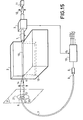
- FIG. 15 illustrates the device implementing the method according to the invention.
- the fiber 1 to be measured is for example stripped and one of its ends is prepared (sawing and polishing or very clean breaking).
- the length of the thus stripped fiber 15 is maintained in a high-precision vacuum mandrel 2 and a device 3 imparts a rotational movement to the fiber 1 so that it can rest on the rectified surfaces of the mandrel forming a dihedral.
- the prepared face 4 of the fiber 1 arrives at the edge of the dihedral.
- An enlarged image of the near field of the fiber is made in a plane P.
- the great straightness of the walls of the dihedral as well as the very good circularity of the silica tube surrounding the fiber allows to know with a good precision the center of the image of the mechanical sheath of the fiber 1 in the plane P.
- the end 6 of a single-mode fiber 7 is placed in the plane P so as to meet there the image 20 of the core of the fiber 1.
- the other end 8 of this fiber is placed in front of a photodetector 9 coupled to a processing electronics 10 intended to look at the signal received at frequencies equal, double, triple ... of a given frequency f 0 .
- Light is injected into the fiber 1 thanks to a source 11 and to a coupling optic 12.
- the device 3 drives the fiber 1 with a rotation movement of the frequency f.
- the reading at the different frequencies f, 2f o , 3f o ... of the signals supplied by the electronics 10 gives the information sought: core-sheath concentricity, ellipticity of the heart etc. ...
- the position of the fiber is identified with respect to the rectified and polished faces of a V-shaped groove and held firmly by the vacuum created via a slot 13 specially studied and optimized for the diameter of the fiber considered.
- the fiber 1 has a short length which does not require it to be wound on a drum for example.
- the light beam emitted by the light source 11 which is for example an incoherent light source is collimated by the objective 12 to reach the core of the optical fiber 1.
- the mechanical sheath of this optical fiber 2 has been exposed at the end 15 of this fiber 1; this part being positioned in the high-precision vacuum mandrel, the slit 13 of which allows, by vacuum, to maintain contact between the length of the requested fiber 15 and the mandrel 2.
- This device 3 can for example be composed of rotating rollers which wedge the fiber by rotating it.
- the light beam which leaves the exit face 4 of the fiber is projected via the objective 14 into the plane P on which we recognize the center circle O representing the mechanical sheath of the fiber and the corresponding center ellipse O ' at the heart of this fiber.
- the end of the fiber 7 considered by way of example is used as a point detector 6; this detector describing a relative circle with respect to the ellipse representative of the core of the fiber 1.
- the fiber 7 makes it possible to make the connection with a detector 9 itself connected to a processing circuit 10 which comprises a synchronous detector of the frequency of rotation f.
- the fiber When the fiber is a multimode fiber, it is arranged to empty the modes transmitted in the sheath, for example by bathing part of the stripped fiber in a liquid of index, which allows to have a greater dynamic of measured.
- the fiber length taken into account is considered to be less than 10 meters, indeed for this length the modal equilibrium law is carried out for a multimode fiber, and for a single mode fiber wound on a drum, the sheath modes have been emptied, for longer lengths then propagation losses appear.
- the invention finds a main application in characterization of optical fibers as well as in connection for optical fiber to the automatic centering of the core of a fiber in a connector end-piece.
Abstract
L'invention concerne un procédé et un dispositif de mesure de la concentricité coeur optique-gaine mécanique et de l'ellipticité du coeur optique d'une fibre optique. Ce procédé consiste à injecter dans une fibre un faisceau lumineux, cette fibre (1) ayant été préalablement dénudée à l'une de ses extrémités. L'analyse du champ proche de cette fibre par un détecteur (6) animé d'un mouvement de rotation relative par rapport à cette fibre (1) permet, en effectuant une détection en bande étroite à la fréquence de rotation (f0) et à sa fréquence double (2f0) de connaître la valeur de la concentricité (e) coeur gaine et celle de l'ellipticité (ε) du coeur. Ce procédé s'applique, notamment, en connectique de fibres optiques.The invention relates to a method and a device for measuring the optical core-mechanical cladding concentricity and the ellipticity of the optical core of an optical fiber. This process consists in injecting a light beam into a fiber, this fiber (1) having been previously stripped at one of its ends. The analysis of the near field of this fiber by a detector (6) animated by a relative rotational movement with respect to this fiber (1) allows, by carrying out a detection in narrow band at the rotation frequency (f0) and at its double frequency (2f0) of knowing the value of the concentricity (e) core sheath and that of the ellipticity (ε) of the heart. This process applies, in particular, in optical fiber connectors.
Description
La présente invention se rapporte à un procédé de mesure simultanée de caractéristiques géométriques d'une fibre optique et notamment de la concentricité coeur optique-gaine mécanique et de l'ellipticité du coeur optique d'une fibre optique et à un dispositif de mise en oeuvre de ce procédé.The present invention relates to a method for simultaneous measurement of geometric characteristics of an optical fiber and in particular of the optical core-mechanical cladding concentricity and of the ellipticity of the optical core of an optical fiber and to an implementation device. of this process.
Comme il est connu, une fibre optique comporte un coeur et une gaine optique. Le coeur et la gaine se différencient essentiellement par leur indice de réfraction optique. L'évolution de cet indice de réfraction optique s'effectue selon un profil déterminé. Après tréfilage, la fibre optique est constituée le plus souvent de ces deux régions, d'un tube support et d'une gaine de protection extérieure disposée autour de ce tube support dans une phase de fabrication ultérieure.As is known, an optical fiber comprises a core and an optical cladding. The core and the sheath are essentially differentiated by their optical refractive index. The evolution of this optical refraction index takes place according to a determined profile. After drawing, the optical fiber usually consists of these two regions, a support tube and an external protective sheath disposed around this support tube in a subsequent manufacturing phase.
Il existe deux types de fibres :
- - des fibres optiques du type dit multimode, le plus souvent à gradient d'indice, pour lesquelles le diamètre de coeur est typiquement de 50 micromètres et le diamètre extérieur de la gaine optique est de 70 micromètres ;
- - des fibres du type dit monomode, le plus souvent à saut d'indice, pour lesquelles le diamètre de coeur est compris entre 5 et 10 micromètres et le diamètre extérieur de la gaine optique est d'environ 40 micromètres.
- - optical fibers of the so-called multimode type, most often with index gradient, for which the core diameter is typically 50 micrometers and the outside diameter of the optical cladding is 70 micrometers;
- - Fibers of the so-called single-mode type, most often with index jump, for which the core diameter is between 5 and 10 micrometers and the outside diameter of the optical cladding is approximately 40 micrometers.
Le diamètre extérieur du tube support, le plus souvent en silice pure, est d'environ 125 micromètres et le diamètre extérieur de la gaine de protection, en silicone par exemple, est de l'ordre de 300 micromètres.The outside diameter of the support tube, most often made of pure silica, is around 125 micrometers and the outside diameter of the protective sheath, made of silicone for example, is of the order of 300 micrometers.
L'apparition de fibres optiques en silice/silice dopée a permis de diminuer dans de grandes proportions les pertes de transmission optiques des fibres optiques. Actuellement des fibres ayant des pertes inférieures à 0,5 dB par km peuvent être réalisées. Il est nécessaire, pour obtenir de telles performances, que les fibres soient très homogènes. En particulier, pour obtenir un couplage entre deux fibres présentant de faibles pertes, il faut que les caractéristiques géométriques de ces deux fibres soient très voisines. Il est donc nécessaire de contrôler ces caractéristiques avec une grande précision ; et parmi celles-ci la concentricité coeur-gaine et l'ellipticité du coeur. Il est d'autre part nécessaire d'effectuer un nombre suffisant de mesures pour s'assurer de l'homogénéité de ces caractéristiques géométriques le long de la fibre.The appearance of optical fibers made of silica / doped silica has made it possible to reduce the optical transmission losses of optical fibers in large proportions. Currently fibers with losses of less than 0.5 dB per km can be produced. To obtain such performance, the fibers must be very homogeneous. In particular, to obtain a coupling between two fibers having low losses, the geometrical characteristics of these two fibers must be very similar. It is therefore necessary to control these characteristics with great precision; and among these is the core-sheath concentricity and the ellipticity of the heart. On the other hand, it is necessary to carry out a sufficient number of measurements to ensure the homogeneity of these geometrical characteristics along the fiber.
Il est connu d'effectuer ces mesures à l'aide d'un microscope en utilisant un réticule comprenant deux cercles concentriques correspondant au coeur optique et à la gaine mécanique d'une fibre optique idéale ; c'est à dire de coeur optique et de gaine mécanique parfaitement cylindriques et concentriques l'un par rapport à l'autre, le coeur de cette fibre optique étant éclairé par un faisceau de lumière blanche. Dans ce cas l'enveloppe de protection a été enlevée avant la mesure. Mais cette mesure ne permet que d'effectuer un tri par rapport à des valeurs d'ellipticité et d'excentricité limites. Elle ne donne pas d'ordre de grandeur de celles-ci.It is known to carry out these measurements using a microscope using a reticle comprising two concentric circles corresponding to the optical core and to the mechanical sheath of an ideal optical fiber; that is to say of optical core and mechanical sheath which are perfectly cylindrical and concentric with one another, the core of this optical fiber being illuminated by a beam of white light. In this case the protective cover was removed before the measurement. However, this measurement only allows sorting with respect to limit ellipticity and eccentricity values. It does not give an order of magnitude of these.
Ce procédé est donc purement manuel, et ne permet pas d'effectuer des mesures précises des caractéristiques à mesurer, il ne permet qu'un tri.This process is therefore purely manual, and does not allow precise measurements of the characteristics to be measured, it only allows sorting.
L'invention, tout au contraire, propose un procédé et un dispositif de mise en oeuvre de ce procédé ne nécessitant qu'un appareillage simple et permettant la mesure précise des paramètres précités de façon automatique. De plus il n'est plus nécessaire de déterminer les dimensions géométriques de la fibre avant d'effectuer la mesure de ces paramètres, ce qui n'était pas vrai dans les procédés de l'art connu.The invention, on the contrary, proposes a method and a device for implementing this method requiring only a simple apparatus and allowing the precise measurement of the aforementioned parameters automatically. Furthermore, it is no longer necessary to determine the geometric dimensions of the fiber before measuring these parameters, which was not true in the processes of the known art.
L'invention a pour objet un procédé de mesure de caractéristiques géométriques d'une fibre optique qui comporte au moins un coeur optique, une gaine mécanique et une gaine de protection, cette mesure comprenant au moins la mesure de la concentricité du coeur optique, et de la gaine mécanique, et de l'ellipticité du coeur, caractérisé en ce qu'il comprend :
- - une première étape de préparation de la fibre à mesurer consistant à mettre à nu la gaine mécanique d'une longueur de cette fibre à une première extrémité de celle-ci, à scier et à polir la face de cette première extrémité de cette fibre ;
- - une deuxième étape de positionnement d'une source de lumière incohérente produisant un faisceau lumineux face à la deuxième extrémité de cette fibre pour envoyer ce faisceau lumineux à l'intérieur de cette fibre ;
- - une troisième étape d'analyse du champ proche de cette fibre à sa première extrémité consistant à former dans un plan une image agrandie de la face de sortie de cette première extrémité de la fibre, un photodétecteur étant placé dans ce plan, une rotation relative par rapport au centre de la gaine mécanique de la fibre étant réalisée entre cette image et ce photodétecteur, cette rotation étant effectuée à une fréquence f ;
- - une quatrième étape de traitement du signal reçu par ce photodétecteur comprenant :
- - une phase de calibration de la mesure par comparaison à des signaux de référence ;
- - une phase de détection de l'amplitude du signal reçu par le photodétecteur aux fréquences multiples de la fréquence de rotation f ;
- - une phase de détermination de la concentricité coeur optique, gaine mécanique et de l'ellipticité du coeur optique de la fibre à partir des amplitudes mesurées aux fréquences f et 2f .
- - A first step of preparing the fiber to be measured consisting of exposing the mechanical sheath of a length of this fiber at a first end thereof, sawing and polishing the face of this first end of this fiber;
- - A second step of positioning an incoherent light source producing a light beam opposite the second end of this fiber to send this light beam inside this fiber;
- a third step of analysis of the near field of this fiber at its first end consisting in forming in a plane an enlarged image of the exit face of this first end of the fiber, a photodetector being placed in this plane, a relative rotation relative to the center of the mechanical sheath of the fiber being produced between this image and this photodetector, this rotation being carried out at a frequency f;
- a fourth step of processing the signal received by this photodetector comprising:
- - a measurement calibration phase by comparison with reference signals;
- a phase for detecting the amplitude of the signal received by the photodetector at frequencies multiple of the rotation frequency f;
- a phase for determining the concentricity of the optical core, mechanical sheath and of the ellipticity of the optical core of the fiber from the amplitudes measured at frequencies f and 2f.
L'invention a également pour objet un dispositif mettant en oeuvre ce procédé.The invention also relates to a device implementing this method.
L'invention sera mieux comprise et d'autres avantages apparaitront à l'aide de la description qui suit, en référence aux figures annexées :
- - la figure 1 met en évidence les paramètres à mesurer ;
- - les figures 2 à 13 illustrent différentes configurations de fibres optiques ainsi que les signaux correspondants donnés par le procédé ;
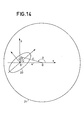
- - la figure 14 met en évidence les paramètres à mesurer ;
- - la figure 15 représente le dispositif mettant en oeuvre le procédé de l'invention.
- - Figure 1 highlights the parameters to be measured;
- - Figures 2 to 13 illustrate different configurations of optical fibers as well as the corresponding signals given by the method;
- - Figure 14 highlights the parameters to be measured;
- - Figure 15 shows the device implementing the method of the invention.
Les paramètres à mesurer sur une fibre optique sont de natures physiques très différentes ; il est ainsi intéressant d'effectuer certains groupements au niveau de la caractérisation suivant le paramètre physique mis en oeuvre. On applique la classification suivante :
- Caractéristiques géométriques : Elles regroupent toutes les mesures ayant un rapport avec les dimensions du coeur, de la gaine et certains revêtements de la fibre.
- Caractéristiques optiques : Elles portent sur toutes les mesures optiques pouvant être effectuées dans un plan de section droite de la fibre (ex : ouverture numérique, profil d'indice ...).
- Caractéristiques de transmission : Elles regroupent toutes les mesures portant sur la propagation de la lumière dans la fibre, qu'il s'agisse des caractéristiques propres à la porteuse (atténuation) ou de celles propres à la modulation (réponse en bande de base). Les mesures de longueur et de continuité de guide optique sont également comprises dans ce paragraphe.
- Caractéristiques mécaniques : Elles portent sur un ensemble de tests (tension, traction, vibration ...) à faire subir à la fibre, afin de lui garantir une bonne résistance mécanique directement reliée à sa durée de vie.
- Geometric characteristics: They include all the measurements having a relationship with the dimensions of the core, the sheath and certain coatings of the fiber.
- Optical characteristics: They relate to all the optical measurements which can be carried out in a plane of cross section of the fiber (ex: numerical aperture, index profile ...).
- Transmission characteristics: They include all the measurements relating to the propagation of light in the fiber, whether these characteristics specific to the carrier (attenuation) or those specific to modulation (baseband response). The optical guide length and continuity measurements are also included in this paragraph.
- Mechanical characteristics: They relate to a set of tests (tension, traction, vibration ...) to be subjected to the fiber, in order to guarantee good mechanical resistance directly related to its lifespan.
Dans le cas des caractéristiques géométriques de la fibre, deux approches peuvent être faites pour mesurer ces paramètres, si importants dans les problèmes de connexion.In the case of the geometric characteristics of the fiber, two approaches can be made to measure these parameters, which are so important in connection problems.
La première, qui peut être qualifiée d'analytique consiste à mesurer indépendamment les uns des autres les paramètres géométriques d'une section droite de fibre. On mesure ainsi :
- - le diamètre de coeur et sa non-circularité,
- - le diamètre de gaine et sa non-circularité,
- - le diamètre du premier revêtement plastique et sa non-circularité,
- - la non-concentricité du coeur et de la gaine,
- - la non-concentricité du coeur et du revêtement primaire. Les nominales et les tolérances sur chacun de ces paramètres étant connues, on déterminera ainsi paramètre par paramètre si la fibre convient.
- - the core diameter and its non-circularity,
- - the sheath diameter and its non-circularity,
- - the diameter of the first plastic coating and its non-circularity,
- - the non-concentricity of the heart and the sheath,
- - the non-concentricity of the heart and the primary coating. The nominal values and tolerances on each of these parameters being known, it will thus be determined parameter by parameter if the fiber is suitable.
La seconde, qu'on peut appeler synthétique, consiste à définir un gabarit de cercles concentriques, à partir des valeurs nominales et des tolérances du coeur et de la gaine et à vérifier si l'image donnée par une section droite de fibre rentre ou non dans ce gabarit.The second, which can be called synthetic, consists in defining a template of concentric circles, starting from the nominal values and the tolerances of the core and the cladding and in checking whether the image given by a straight section of fiber fits or not in this template.
Quelle que soit la procédure employée, il faut réaliser une image agrandie d'une section droite de la fibre. Celle-ci est obtenue en réalisant un montage optique, voisin de celui rencontré dans un microscope, qui visualise le champ proche d'un objet soumis à illumination.Whichever procedure is used, an enlarged image of a cross section of the fiber must be produced. This is obtained by performing an optical montage, similar to that encountered in a microscope, which visualizes the near field of an object subjected to illumination.
La source de lumière qui éclaire la fibre doit être très divergente pour exciter également tous les modes de la fibre, et ne doit pas être nécessairement monochromatique (lampe à arc par exemple).The light source which illuminates the fiber must be very divergent to also excite all the modes of the fiber, and does not have to be necessarily monochromatic (arc lamp for example).
La longueur de l'échantillon est en général courte, les extrémités étant soigneusement préparées.The length of the sample is generally short, the ends being carefully prepared.
Le procédé de l'invention se rattache à cette première approche qualifiée d'analytique.The method of the invention relates to this first approach, which is described as analytical.
Ainsi le procédé permet la mesure quantitative simultanée de deux paramètres très important pour la connexion de deux fibres optiques qui sont la concentricité coeur optique-gaine mécanique et l'ellipticité du coeur optique de ces fibres et ce, de manière simple. Le procédé permet aussi de trouver les symétries d'ordres supérieures (3, 4 ...) du coeur en employant le même principe de base.Thus the method allows the simultaneous quantitative measurement of two very important parameters for the connection of two optical fibers which are the concentricity optical core-mechanical sheath and the ellipticity of the optical core of these fibers and this, in a simple manner. The method also makes it possible to find the symmetries of higher orders (3, 4 ...) of the heart by using the same basic principle.
Sur la figure 1 représentant une image agrandie d'une section droite de la fibre, la gaine mécanique 22 a un centre de symétrie O, et le coeur optique 20 a un centre de symétrie O', la concentricitée est la valeur 00', et l'ellipticité E est donné par la formule : e2 = a2 - b2 : a étant le demi grand axe de l'ellipse représentant le coeur, et b le demi petit axe de cette même ellipse.In FIG. 1 representing an enlarged image of a cross section of the fiber, the
Le procédé de l'invention présente l'avantage sur les autres procédés de ne pas avoir à déterminer les dimensions géométriques de la fibre pour obtenir les défauts d'excentrement coeur gaine et les symétries d'ordre 2(ellipticité) et d'ordres supérieurs du coeur. En outre, le procédé mettant en oeuvre ce procédé permet d'éliminer les erreurs de mesure de l'opérateur en grande partie subjectives dans les procédés actuels par l'utilisation d'une électronique de mesure stable d'un signal optique issu de la fibre à caractériser.The method of the invention has the advantage over the other methods of not having to determine the geometrical dimensions of the fiber in order to obtain the sheath core eccentricity defects and the symmetries of order 2 (ellipticity) and of higher orders. of the heart. In addition, the method implementing this method makes it possible to eliminate the largely subjective operator measurement errors in current methods by the use of stable measurement electronics for an optical signal originating from the fiber. to characterize.
Un dispositif mettant en oeuvre le procédé de l'invention sera décrit dans la suite de la description en explication de la figure 15.A device implementing the method of the invention will be described in the following description in explanation of FIG. 15.
Le procédé de l'invention est le suivant : De la lumière incohérente est envoyée dans une courte longueur de fibre optique (de 1 à 10 mètres) et est récupérée à l'autre extrémité de la fibre, extrémité que l'on aura pris soin de bien préparer ; dénudage des protections extérieures, sciage, puis polissage par exemple. Le champ proche de la fibre à mesurer est ensuite agrandi grâce à un dispositif optique et analysé grâce à une photodiode quasi ponctuelle animée d'un mouvement de rotation autour du centre du cercle supposé parfait qui définit l'extérieur de la gaine mécanique de la fibre. La détection du signal lu par la photodiode en bande étroite autour de fréquences multiples de la fréquence f de rotation de la photodiode donne les informations recherchées. L'amplitude à fo est liée à la concentricité coeur gaine, celle à 2fo à l'ellipticité du coeur, celle à 3f0 à sa symétrie d'ordre 3 etc ... Dans le cas d'un profil d'indice parabolique le calcul permet de montrer que l'amplitude à fo est proportionnelle à la concentricité coeur gaine, que celle à 2f0 est proportionnelle au carré de l'ellipticité du coeur. Un étalonnage préalable du dispositif permet par exemple de déterminer les constantes de proportionnalité à différentes fréquences.The process of the invention is as follows: Inconsistent light is sent through a short length of optical fiber (from 1 to 10 meters) and is recovered at the other end of the fiber, which end has been taken care of to prepare well; stripping of external protections, sawing, then polishing for example. The near field of the fiber to be measured is then enlarged using an optical device and analyzed using a quasi-point photodiode animated by a rotation movement around the center of the supposedly perfect circle which defines the outside of the mechanical sheath of the fiber. . Detection of the signal read by the narrow-band photodiode around frequencies multiple of the frequency f of rotation of the photodiode gives the information sought. The amplitude at f o is linked to the concentricity of the core sheath, that at 2f o to the ellipticity of the heart, that at 3f 0 to its order 3 symmetry etc ... In the case of an index profile parabolic the calculation allows to show that the amplitude at f o is proportional to the concentricity core sheath, that that at 2f 0 is proportional to the square of the ellipticity of the heart. A prior calibration of the device makes it possible for example to determine the constants of proportionality at different frequencies.
Différentes configurations d'une section droite de la fibre sont à considérer, au vu du signal de mesure qui donne la puissance lumineuse reçue par la photodiode en fonction de l'instant 0, et de la transformée de Fourier de ce signal qui permet de mettre en évidence les raies des fréquences f , 2f et 3f.Different configurations of a cross section of the fiber are to be considered, in view of the measurement signal which gives the light power received by the photodiode as a function of
Sur la figure 2, O est le centre de la gaine mécanique 21 de la fibre qui est ici considéré comme un cylindre parfait et O' est le centre du cercle 20 qui représente le coeur de la fibre.In FIG. 2, O is the center of the
On fait donc tourner selon le cercle 22 un détecteur autour de O, ou ce qui revient au même on peut faire tourner la fibre ; la rotation relative est donc représentée par le cercle 20 en considérant un détecteur fixe. Il suffit donc de dire qu'il y a une rotation relative 22 entre le détecteur et l'image agrandie du champ proche de la face de la fibre dans un plan P qui est le plan dans lequel se situent les différentes configurations de fibre que l'on va examiner ci-dessous.A detector is therefore made to rotate around
Si la fibre est parfaite, comme représenté à la figure 2 O est alors confondu avec O', le cercle 22 qui décrit le mouvement relatif du détecteur par rapport à la fibre ne coupera pas l'ellipse représentant le coeur, dont le grand axe sera égal au petit axe, c'est donc un cercle concentrique du cercle 21 de la gaine.If the fiber is perfect, as shown in Figure 2 O is then confused with O ', the
Ainsi la puissance lumineuse sera alors une constante comme illustré à la figure 6.Thus the light power will then be a constant as illustrated in Figure 6.
La transformée de Fourier de ce signal est représenté à la figure 4. Il ne comporte qu'une raie à la fréquence o.The Fourier transform of this signal is shown in Figure 4. It has only one line at frequency o.
Si le coeur est représenté par un cercle, mais si celui-ci est décentré comme à la figure 5, O et O' ne sont plus confondus. On a alors à la figure 6 la courbe représentative de la puissance lumineuse 2 en fonction de l'instant 0 de la rotation relative du détecteur par rapport à la fibre. On voit ainsi apparaitre une raie à la fréquence fo de la rotation, cette raie apparait sur la figure 7 qui est la transformée de Fourier du signal reçu par le détecteur.If the heart is represented by a circle, but if the latter is off-center as in Figure 5, O and O 'are no longer confused. There is then in FIG. 6 the curve representing the
Si, à présent, le coeur de la fibre est représenté par une ellipse 20 comme à la figure 8. La courbe représentée à la figure 9 de la puissance lumineuse en fonction de l'instant 0 présente deux raies : elle présente une composante à la fréquence de la rotation fo ainsi qu'à une fréquence double 2f . Si O et O' sont confondus l'amplitude de ces deux raies est alors identique. La transformée de Fourier de ce signal est représentée à la figure 10.If, now, the core of the fiber is represented by an
Si le cercle 22 de la rotation relative du détecteur ne coupe pas cette ellipse, c'est que le coeur est vraiment trop excentré, cette fibre doit alors être éliminée.If the
Si la courbe représentative du coeur est de forme plus torturée, l'ellipticité peut alors être du troisième ordre et la courbe de la puissance en fonction de l'instant 0 présente alors trois raies comme représenté aux figures 11, 12 et 13. Sur la figure 11 on considère une image du coeur de forme symétrique par rapport à trois segments issus du centre O' et formant des angles de 120° entre eux, aussi n'y a t-il à la figure 13 représentant la transformée du signal reçu que deux raies l'une à f l'autre à 3fo If the curve representative of the heart is more tortured in shape, the ellipticity can then be of the third order and the curve of the power as a function of
Mais l'amplitude de ces différentes raies à fo, 2f , 3f va permettre de calculer les caractéristiques géométriques recherchées de la fibre.But the amplitude of these different lines at f o , 2f, 3f will make it possible to calculate the desired geometric characteristics of the fiber.
Dans le cas d'une bonne fibre, c'est à dire lorsque le coeur n'est pas trop décentré, la puissance reçue par le détecteur n'influe pas sur le nombre de raies, mais seulement sur l'amplitude de ces raies.In the case of a good fiber, that is to say when the core is not too off-center, the power received by the detector does not influence the number of lines, but only the amplitude of these lines.
En effet, lorsqu'un point décrit un cercle de rayon φ centré en O à une vitesse ![]()

![]()
Sur la figure 14, O est le centre de l'image agrandie de la face de la fibre, O' le centre de symétrie du coeur optique de celle-ci.In FIG. 14, O is the center of the enlarged image of the face of the fiber, O ′ the center of symmetry of the optical core thereof.
OO' est le décentrement entre le coeur et la gaine de la fibre : 00' = e et ε l'ellipticité du coeur de la fibre telle que e2 = a2 - b2.OO 'is the offset between the core and the fiber cladding: 00' = e and ε the ellipticity of the fiber core such that e 2 = a 2 - b2.
Dans le cas d'un coeur elliptique à répartition d'indice de réfraction parabolique et d'un coeur décentré par rapport à la gaine, l'indice de réfraction du coeur dans les axes de l'ellipse est donné par :
Une bonne approximation consiste à dire que la puissance lumineuse en tout point du champ proche est proportionnelle au carré de l'indice en ce point. On supposera P(r,φ) = kn2 (r,φ)A good approximation is to say that the light power at any point in the near field is proportional to the square of the index at this point. We will assume P (r, φ) = kn2 (r, φ)
Si on se ramène au centre de la rotation dans un repère fixe dans lequel le photodétecteur occupe une position fixe.
![]()

![]()
![]()

![]()
![]()
![]()
Ainsi la raie obtenue par la transformée de Fourier du signal reçu par le détecteur à la fréquence de rotation f0 est proportionnelle à e et la raie à une fréquence double de la fréquence de rotation proportionnelle à e: 2.Thus the line obtained by the Fourier transform of the signal received by the detector at the frequency of rotation f 0 is proportional to e and the line at a frequency twice the frequency of rotation proportional to e: 2.
La fibre prise à titre d'exemple indicatif dans les calculs précédents est une fibre fortement multimode pour laquelle le profil d'indice, en se rapprochant du coeur est à peu près parabolique, c'est à dire que la puissance lumineuse est donnée par la relation P = k n2.The fiber taken as an example in the previous calculations is a highly multimode fiber for which the index profile, approaching the core is roughly parabolic, that is to say that the light power is given by the relation P = kn 2 .
Dans une fibre monomode ce profil est un signal gaussien.In a single mode fiber this profile is a Gaussian signal.
Ainsi dans les calculs, la fibre considérée était une fibre fortement multimode, aussi on a employé, pour la simplicité de ces calculs, une puissance de forme parabolique en fonction du rayon. Pour une fibre monomode, en toute rigueur, il faut recommencer les calculs avec une puissance gaussienne en fonction du rayon mais l'on obtient les mêmes résultats.Thus in the calculations, the fiber considered was a highly multimode fiber, so we used, for the simplicity of these calculations, a power of parabolic shape as a function of the radius. For a monomode fiber, in all rigor, it is necessary to start again the calculations with a Gaussian power according to the radius but one obtains the same results.
La figure 15 illustre le dispositif mettant en oeuvre le procédé selon l'invention.FIG. 15 illustrates the device implementing the method according to the invention.
La fibre 1 à mesurer est par exemple dénudée et une de ses extrémités est préparée (sciage et polissage ou cassure très propre). La longueur de la fibre ainsi dénudée 15 est maintenue dans un mandrin à vide 2 de haute précision et un dispositif 3 imprime un mouvement de rotation à la fibre 1 de manière à ce que celle-ci puisse s'appuyer sur les surfaces rectifiées du mandrin formant dièdre. La face préparée 4 de la fibre 1 arrive au bord du dièdre. Une image agrandie du champ proche de la fibre est faite dans un plan P. La grande rectitude des parois du dièdre ainsi que la très bonne circularité du tube de silice entourant la fibre permet de connaitre avec une bonne précision le centre de l'image de la gaine mécanique de la fibre 1 dans le plan P. L'extrémité 6 d'une fibre monomode 7 est placée dans le plan P de manière à y rencontrer l'image 20 du coeur de la fibre 1. L'autre extrémité 8 de cette fibre est placée devant un photodétecteur 9 couplé à une électronique de traitement 10 destinée à regarder le signal reçu à des fréquences égale, double, triple ... d'une fréquence f0 donnée. De la lumière est injectée dans la fibre 1 grâce à une source 11 et à une optique de couplage 12. Le dispositif 3 anime la fibre 1 d'un mouvement de rotation de la fréquence f . Après étalonnage de la manipulation par comparaison à des signaux de référence, la lecture aux différentes fréquences f , 2fo, 3fo ... des signaux fournis par l'électronique 10 donne les renseignements cherchés : concentricité coeur-gaine, ellipticité du coeur etc ...The
Dans le mandrin à vide 2 ou mandrin à dépression pour fibres optiques, la position de la fibre est repérée par rapport aux faces rectifiées et polies d'un sillon en V et maintenue fermement par le vide créé via une fente 13 spécialement étudiée et optimisée pour le diamètre de la fibre considérée.In the
Sur la figure 15, la fibre 1 a une faible longueur qui ne nécessite pas de l'enrouler sur un tambour par exemple.In FIG. 15, the
Mais elle peut avoir une longueur comprise, par exemple entre 1 et 10 mètres. Mais dans le cas d'une plus grande longueur elle est enroulée sur un tambour, et on fait tourner l'ensemble source 11, objectif 12, tambour sur lequel est enroulé la partie de la fibre non dénudée et qui ainsi est située entre le mandrin 2 et la source 11, mandrin 2, à la fréquence fo considérée.But it can have a length of, for example, between 1 and 10 meters. But in the case of a greater length it is wound on a drum, and the source assembly 11, objective 12, is rotated, drum on which is wound the part of the non-stripped fiber and which is thus located between the
Ainsi sur cette figure 15 le faisceau de lumière émis par la source de lumière 11 qui est par exemple une source de lumière incohérente est collimaté par l'objectif 12 pour atteindre le coeur de la fibre optique 1. La gaine mécanique de cette fibre optique 2 a été mise à nu à l'extrémité 15 de cette fibre 1 ; cette partie étant positionnée dans le mandrin à vide de haute précision dont la fente 13 permet par dépression de maintenir le contact entre la longueur de la fibre demandée 15 et le mandrin 2. Le dispositif 3 permet de faire tourner cette fibre 3 à la fréquence de rotation ωo = 2π f . Ce dispositif 3 peut être par exemple composé de galets en rotation qui coincent la fibre en la faisant tourner.Thus in this figure 15 the light beam emitted by the light source 11 which is for example an incoherent light source is collimated by the objective 12 to reach the core of the
Le faisceau lumineux qui sort de la face de sortie 4 de la fibre est projeté via l'objectif 14 dans le plan P sur lequel on reconnait le cercle de centre O représentant la gaine mécanique de la fibre et l'ellipse de centre O' correspondant au coeur de cette fibre.The light beam which leaves the exit face 4 of the fiber is projected via the objective 14 into the plane P on which we recognize the center circle O representing the mechanical sheath of the fiber and the corresponding center ellipse O ' at the heart of this fiber.
Le bout de la fibre 7 considéré à titre d'exemple est utilisé comme détecteur ponctuel 6 ; ce détecteur décrivant un cercle relatif par rapport à l'ellipse représentative du coeur de la fibre 1. La fibre 7 permet de faire la liaison avec un détecteur 9 lui même relié à un circuit de traitement 10 qui comprend un détecteur synchrone de la fréquence de rotation f .The end of the
Il est tout aussi possible de considérer une fibre 1 fixe et de faire tourner le détecteur ponctuel 6.It is also possible to consider a fixed
Les différents alignements réalisés entre la source et la fibre via l'objectif entre l'extrémité de la fibre et le détecteur, ainsi que le positionnement de l'autre extrémité de la fibre 1 dans le plan P sont du domaine de l'art connu.The different alignments made between the source and the fiber via the objective between the end of the fiber and the detector, as well as the positioning of the other end of the
Il n'y a pas nécessité de précision d'alignement de la fibre par rapport au mandrin à vide.There is no need for precise alignment of the fiber with respect to the vacuum mandrel.
Lorsque la fibre est une fibre multimode, on s'arrange pour vider les modes transmis dans la gaine, par exemple en faisant baigner une partie de la fibre dénudée dans un liquide d'indice, ce qui permet d'avoir une plus grande dynamique de mesure.When the fiber is a multimode fiber, it is arranged to empty the modes transmitted in the sheath, for example by bathing part of the stripped fiber in a liquid of index, which allows to have a greater dynamic of measured.
La longueur de fibre prise en compte est considérée inférieure à 10 mètres, en effet pour cette longueur la loi d'équilibre modale est réalisée pour une fibre multimode, et pour une fibre monomode enroulée sur un tambour, on a vidé les modes de gaine, pour de plus grandes longueurs apparaissent alors des pertes de propagation.The fiber length taken into account is considered to be less than 10 meters, indeed for this length the modal equilibrium law is carried out for a multimode fiber, and for a single mode fiber wound on a drum, the sheath modes have been emptied, for longer lengths then propagation losses appear.
L'invention trouve une application principale en caractérisation de fibres optiques ainsi qu'en connectique pour fibre optique au centrage automatique du coeur d'une fibre dans un embout de connecteur.The invention finds a main application in characterization of optical fibers as well as in connection for optical fiber to the automatic centering of the core of a fiber in a connector end-piece.
Claims (8)
Applications Claiming Priority (2)
| Application Number | Priority Date | Filing Date | Title |
|---|---|---|---|
| FR8208479A FR2526935A1 (en) | 1982-05-14 | 1982-05-14 | METHOD AND DEVICE FOR SIMULTANEOUS MEASUREMENT OF GEOMETRIC CHARACTERISTICS OF AN OPTICAL FIBER |
| FR8208479 | 1982-05-14 |
Publications (2)
| Publication Number | Publication Date |
|---|---|
| EP0094864A1 true EP0094864A1 (en) | 1983-11-23 |
| EP0094864B1 EP0094864B1 (en) | 1986-08-20 |
Family
ID=9274055
Family Applications (1)
| Application Number | Title | Priority Date | Filing Date |
|---|---|---|---|
| EP83400892A Expired EP0094864B1 (en) | 1982-05-14 | 1983-05-03 | Process and device for the simultaneous measurement of geometrical characteristics of an optical fibre |
Country Status (6)
| Country | Link |
|---|---|
| US (1) | US4563087A (en) |
| EP (1) | EP0094864B1 (en) |
| JP (1) | JPS58213225A (en) |
| CA (1) | CA1195839A (en) |
| DE (1) | DE3365418D1 (en) |
| FR (1) | FR2526935A1 (en) |
Cited By (1)
| Publication number | Priority date | Publication date | Assignee | Title |
|---|---|---|---|---|
| AU585728B2 (en) * | 1986-08-15 | 1989-06-22 | Sumitomo Electric Industries, Ltd. | Method and apparatus of measuring outer diameter and structure of optical fiber |
Families Citing this family (23)
| Publication number | Priority date | Publication date | Assignee | Title |
|---|---|---|---|---|
| DE3810057A1 (en) * | 1988-03-25 | 1989-10-05 | Philips Patentverwaltung | METHOD FOR MEASURING THE Eccentricity of an optical waveguide embedded in a cylindrical plug pin |
| DE3824255A1 (en) * | 1988-07-14 | 1990-01-18 | Siemens Ag | Method and device for the measurement of eccentricity |
| DE3836954A1 (en) * | 1988-10-29 | 1990-05-03 | Philips Patentverwaltung | METHOD AND ARRANGEMENT FOR DETERMINING THE POSITION OF THE OPTICAL AXIS OF A FOC |
| US5072110A (en) * | 1989-09-05 | 1991-12-10 | Canadian Marconi Company | Fiber optic strain and impact sensor system for composite materials |
| US5131745A (en) * | 1990-11-02 | 1992-07-21 | The Charles Stark Draper Lab., Inc. | Method and apparatus for aligning the optical axis of a fiber optic element with the axis of rotation |
| IT1250341B (en) * | 1991-11-15 | 1995-04-07 | PROCEDURE AND EQUIPMENT FOR MEASURING THE GEOMETRIC CHARACTERISTICS OF NOMINALLY CYLINDRICAL GUIDING STRUCTURES. | |
| KR100325687B1 (en) * | 1999-12-21 | 2002-02-25 | 윤덕용 | A low-cost WDM source with an incoherent light injected Fabry-Perot semiconductor laser diode |
| US6421118B1 (en) * | 2000-08-21 | 2002-07-16 | Gn Nettest (Oregon), Inc. | Method of measuring concentricity of an optical fiber |
| US8423110B2 (en) * | 2002-01-09 | 2013-04-16 | Boston Scientific Scimed, Inc. | Imaging device and related methods |
| KR100515259B1 (en) * | 2002-05-03 | 2005-09-15 | 한국과학기술원 | Wavelength-tunable light source and wavelength-division multiplexed transmission system with the sources |
| US7593647B2 (en) * | 2002-09-19 | 2009-09-22 | Novera Optics, Inc. | Apparatuses and methods for automatic wavelength locking of an optical transmitter to the wavelength of an injected incoherent light signal |
| KR100473520B1 (en) | 2002-12-24 | 2005-03-10 | 한국과학기술원 | The optical access network using wavelength-locked WDM optical source injected by incoherent light |
| CN100348945C (en) * | 2003-03-24 | 2007-11-14 | 上海上诠光纤通信设备有限公司 | Method and its device for detecting ceramic insert core opening angle |
| US7515626B2 (en) * | 2003-05-29 | 2009-04-07 | Novera Optics, Inc. | Light source capable of lasing that is wavelength locked by an injected light signal |
| KR100955129B1 (en) * | 2003-05-30 | 2010-04-28 | 정보통신연구진흥원 | wavelength-division multiple access passive optical network using the incoherent broadband light source |
| US7313157B2 (en) * | 2003-12-19 | 2007-12-25 | Novera Optics, Inc. | Integration of laser sources and detectors for a passive optical network |
| US7110657B1 (en) * | 2004-02-23 | 2006-09-19 | Photon Kinetics, Inc. | Method of measuring circularity of an optical fiber |
| DE102005028844B4 (en) * | 2005-06-22 | 2007-07-05 | Luk Lamellen Und Kupplungsbau Beteiligungs Kg | Method and device for controlling a non-self-locking coupling |
| KR100698766B1 (en) * | 2005-09-07 | 2007-03-23 | 한국과학기술원 | Apparatus for Monitoring Failure Positions in Wavelength Division Multiplexing-Passive Optical Networks and Wavelength Division Multiplexing-Passive Optical Network Systems Having the Apparatus |
| KR100785436B1 (en) * | 2005-09-20 | 2007-12-13 | 한국과학기술원 | Wavelength division multiplexing passive optical network for convergence broadcasting service and communication service |
| US8571410B2 (en) * | 2006-10-11 | 2013-10-29 | Novera Optics, Inc. | Mutual wavelength locking in WDM-PONS |
| CN104516057B (en) * | 2013-09-27 | 2017-01-04 | 泰科电子(上海)有限公司 | The aligning device of fiber stub, optical fiber aligner and optical fiber regulation of mental activities method |
| WO2016071530A1 (en) * | 2014-11-07 | 2016-05-12 | Commscope Asia Holdings B.V. | Devices, systems and methods for use in fiber measurements, such as multi-mode fiber geometry measurements |
Citations (3)
| Publication number | Priority date | Publication date | Assignee | Title |
|---|---|---|---|---|
| FR1510948A (en) * | 1966-12-01 | 1968-01-26 | France Etat | Optical devices for measuring the eccentricities of cylindrical blocks |
| FR2437637A1 (en) * | 1978-09-26 | 1980-04-25 | Philips Nv | PROCESS AND DEVICE FOR FORMING A CONCENTRIC ENVELOPE ON AN END OF A PHOTOCONDUCTIVE FIBER, AND FIBER END PROVIDED WITH AN ELABORATED ENVELOPE OF THE KIND |
| US4299491A (en) * | 1979-12-11 | 1981-11-10 | United Technologies Corporation | Noncontact optical gauging system |
-
1982
- 1982-05-14 FR FR8208479A patent/FR2526935A1/en active Granted
-
1983
- 1983-05-03 DE DE8383400892T patent/DE3365418D1/en not_active Expired
- 1983-05-03 EP EP83400892A patent/EP0094864B1/en not_active Expired
- 1983-05-12 CA CA000428009A patent/CA1195839A/en not_active Expired
- 1983-05-13 JP JP58083969A patent/JPS58213225A/en active Pending
- 1983-05-13 US US06/494,253 patent/US4563087A/en not_active Expired - Fee Related
Patent Citations (3)
| Publication number | Priority date | Publication date | Assignee | Title |
|---|---|---|---|---|
| FR1510948A (en) * | 1966-12-01 | 1968-01-26 | France Etat | Optical devices for measuring the eccentricities of cylindrical blocks |
| FR2437637A1 (en) * | 1978-09-26 | 1980-04-25 | Philips Nv | PROCESS AND DEVICE FOR FORMING A CONCENTRIC ENVELOPE ON AN END OF A PHOTOCONDUCTIVE FIBER, AND FIBER END PROVIDED WITH AN ELABORATED ENVELOPE OF THE KIND |
| US4299491A (en) * | 1979-12-11 | 1981-11-10 | United Technologies Corporation | Noncontact optical gauging system |
Cited By (1)
| Publication number | Priority date | Publication date | Assignee | Title |
|---|---|---|---|---|
| AU585728B2 (en) * | 1986-08-15 | 1989-06-22 | Sumitomo Electric Industries, Ltd. | Method and apparatus of measuring outer diameter and structure of optical fiber |
Also Published As
| Publication number | Publication date |
|---|---|
| DE3365418D1 (en) | 1986-09-25 |
| EP0094864B1 (en) | 1986-08-20 |
| US4563087A (en) | 1986-01-07 |
| JPS58213225A (en) | 1983-12-12 |
| CA1195839A (en) | 1985-10-29 |
| FR2526935A1 (en) | 1983-11-18 |
| FR2526935B1 (en) | 1984-11-30 |
Similar Documents
| Publication | Publication Date | Title |
|---|---|---|
| EP0094864B1 (en) | Process and device for the simultaneous measurement of geometrical characteristics of an optical fibre | |
| EP0108671B1 (en) | Apparatus for measuring temperature and/or electric intensity using the faraday effect | |
| CA1296545C (en) | Continuous surface condition control device for a moving web of corrugated paper | |
| EP0414614B1 (en) | Procedure and apparatus for the geometrical characterization of transparent tubes | |
| US7271916B2 (en) | Characterization of optical fiber using Fourier domain optical coherence tomography | |
| EP3201610B1 (en) | Method and system for inspecting transparent wafers for electronics, optics or optoelectronics | |
| FR2800870A1 (en) | Device and procedure for measuring optical dispersion in optical, especially monomode, fiber, in which at least two beams are generated from an initial beam and recombined | |
| EP1131599B1 (en) | Device for measuring the dimension and controlling of defects in optical fibres during production | |
| EP0562911B1 (en) | Method for the relative measurement of the axis of an opening and of the axis of a cylindrical contour | |
| EP0133607B1 (en) | Refractometer for the measurement of the refractive index of a liquid | |
| EP0458752B1 (en) | Method for measuring the angle of incidence of a light beam, measuring device for carrying out the method, and distance measuring device utilising same | |
| EP0101375B1 (en) | Method and apparatus for determining without making contact the roughness of a surface | |
| EP0669525A2 (en) | Interferometrical system for detecting and localising reflective defects of light guide structures | |
| CN107407617B (en) | Devices, systems, and methods for such as optical fiber measurement of multi-mode optical fiber dimensional measurement | |
| FR2940687A1 (en) | OPTICAL FIBER DEVICE FOR INTERFEROMETRIC ANALYSIS OF THE SURFACE CONDITION OF AN OBJECT | |
| US5335057A (en) | Measuring geometry of optical fibre coatings with transverse incident beams | |
| Askins et al. | Technique for controlling the internal rotation of principal axes in the fabrication of birefringent fibers | |
| FR2506930A1 (en) | Position measurement appts. for optic fibre in connector - uses sinusoidally moving projected image and controlled displacement of fibre end until characteristic state of alignment is attained | |
| FR2739445A1 (en) | Fibre optic reflectometry device for physical measurement | |
| JPS5831860B2 (en) | Optical fiber cutoff wavelength measuring device | |
| Presby et al. | Profile Characterization of Optical Fibers and Preforms | |
| Pagnoux et al. | Cut-off wavelength and mode field radius determinations in monomode fibres by means of a new single measurement device | |
| FR3071610A1 (en) | FIBER OPTIC REFLECTOMETRY ANALYSIS SYSTEM | |
| Young et al. | Optical Fiber Measurements | |
| WO2013024229A1 (en) | Optical device for interferometric analysis of the condition of the internal surface of a tube |
Legal Events
| Date | Code | Title | Description |
|---|---|---|---|
| PUAI | Public reference made under article 153(3) epc to a published international application that has entered the european phase |
Free format text: ORIGINAL CODE: 0009012 |
|
| AK | Designated contracting states |
Designated state(s): CH DE GB IT LI NL SE |
|
| 17P | Request for examination filed |
Effective date: 19831203 |
|
| RBV | Designated contracting states (corrected) |
Designated state(s): DE GB IT NL |
|
| GRAA | (expected) grant |
Free format text: ORIGINAL CODE: 0009210 |
|
| AK | Designated contracting states |
Kind code of ref document: B1 Designated state(s): DE GB IT NL |
|
| ITF | It: translation for a ep patent filed |
Owner name: JACOBACCI & PERANI S.P.A. |
|
| REF | Corresponds to: |
Ref document number: 3365418 Country of ref document: DE Date of ref document: 19860925 |
|
| PGFP | Annual fee paid to national office [announced via postgrant information from national office to epo] |
Ref country code: NL Payment date: 19870531 Year of fee payment: 5 |
|
| PLBE | No opposition filed within time limit |
Free format text: ORIGINAL CODE: 0009261 |
|
| STAA | Information on the status of an ep patent application or granted ep patent |
Free format text: STATUS: NO OPPOSITION FILED WITHIN TIME LIMIT |
|
| 26N | No opposition filed | ||
| PG25 | Lapsed in a contracting state [announced via postgrant information from national office to epo] |
Ref country code: GB Effective date: 19880503 |
|
| PG25 | Lapsed in a contracting state [announced via postgrant information from national office to epo] |
Ref country code: NL Effective date: 19881201 |
|
| GBPC | Gb: european patent ceased through non-payment of renewal fee | ||
| NLV4 | Nl: lapsed or anulled due to non-payment of the annual fee | ||
| PG25 | Lapsed in a contracting state [announced via postgrant information from national office to epo] |
Ref country code: DE Effective date: 19890201 |