EP0094798B1 - Nadelpunktdrucker zur Verwendung mit einer Vielzahl verschiedener farbiger Tinten - Google Patents
Nadelpunktdrucker zur Verwendung mit einer Vielzahl verschiedener farbiger Tinten Download PDFInfo
- Publication number
- EP0094798B1 EP0094798B1 EP83302702A EP83302702A EP0094798B1 EP 0094798 B1 EP0094798 B1 EP 0094798B1 EP 83302702 A EP83302702 A EP 83302702A EP 83302702 A EP83302702 A EP 83302702A EP 0094798 B1 EP0094798 B1 EP 0094798B1
- Authority
- EP
- European Patent Office
- Prior art keywords
- ink
- print head
- dot printer
- wire dot
- cleaning member
- Prior art date
- Legal status (The legal status is an assumption and is not a legal conclusion. Google has not performed a legal analysis and makes no representation as to the accuracy of the status listed.)
- Expired
Links
Images


Classifications
-
- B—PERFORMING OPERATIONS; TRANSPORTING
- B41—PRINTING; LINING MACHINES; TYPEWRITERS; STAMPS
- B41J—TYPEWRITERS; SELECTIVE PRINTING MECHANISMS, i.e. MECHANISMS PRINTING OTHERWISE THAN FROM A FORME; CORRECTION OF TYPOGRAPHICAL ERRORS
- B41J2/00—Typewriters or selective printing mechanisms characterised by the printing or marking process for which they are designed
- B41J2/22—Typewriters or selective printing mechanisms characterised by the printing or marking process for which they are designed characterised by selective application of impact or pressure on a printing material or impression-transfer material
- B41J2/23—Typewriters or selective printing mechanisms characterised by the printing or marking process for which they are designed characterised by selective application of impact or pressure on a printing material or impression-transfer material using print wires
- B41J2/235—Print head assemblies
- B41J2/25—Print wires
- B41J2/255—Arrangement of the print ends of the wires
-
- B—PERFORMING OPERATIONS; TRANSPORTING
- B41—PRINTING; LINING MACHINES; TYPEWRITERS; STAMPS
- B41J—TYPEWRITERS; SELECTIVE PRINTING MECHANISMS, i.e. MECHANISMS PRINTING OTHERWISE THAN FROM A FORME; CORRECTION OF TYPOGRAPHICAL ERRORS
- B41J2/00—Typewriters or selective printing mechanisms characterised by the printing or marking process for which they are designed
- B41J2/22—Typewriters or selective printing mechanisms characterised by the printing or marking process for which they are designed characterised by selective application of impact or pressure on a printing material or impression-transfer material
- B41J2/23—Typewriters or selective printing mechanisms characterised by the printing or marking process for which they are designed characterised by selective application of impact or pressure on a printing material or impression-transfer material using print wires
- B41J2/305—Ink supply apparatus
Definitions
- the present invention relates to a wire dot printer adapted to use a plurality of differently coloured inks to effect multicolour printing.
- Impact colour printers which employ a ribbon which has differently coloured areas arranged either longitudinally or transversely.
- This type of impact colour printer can print characters in one colour only while the print head is moving with respect to the paper in a single stroke.
- the print head is required to move along the same line in as many strokes as there are colours to be printed, resulting in a greatly reduced printing speed.
- the service life of the ribbon employed is governed by that of the colour area thereof which is most frequently used.
- more colours than the colours available on the ribbon can be recorded by printing a number of colours on the same dot.
- the ink previously printed on the dot tends to be transferred to the other coloured areas on the ribbon, with the result that the inks of different colours will be mixed together on the ribbon as the latter becomes frequently used.
- wire dot printer having a matrix of wire ends for carrying fluid ink to effect printing.
- the wire dot printer is capable of supplying an appropriate amount of fluid ink to the wire ends for performing stable printing of high quality.
- this wire dot printer was not adapted to use a plurality of differently coloured inks.
- the wire dot printer disclosed in the said co-pending application employs two tubes for supplying fluid nk to a print head and for collecting excess ink.
- a total of six ink supply and collection tubes is required which interconnect the print head with three ink tanks, one tank for each of the inks, the tubes being coupled to predetermined portions of the print head. Accordingly, such a colour printer would be cumbersome to assemble.
- the interior of the print head should have ink passages formed for respective inks in a limited space without causing colour mixing. Therefore, the print head is liable to be complex in structure, cumbersome to put together, and less reliable in operation.
- a wire dot printer comprising a print head which'carries a plurality of printing wires, nd fluid ink application means for applying fluid ink to printing end faces of the printing wires, characterised in that, for the purpose of using a plurality of differently coloured fluid inks to effect multicolour printing, the print head has a plurality of said fluid ink application means, the printing wires being arranged in a plurality of separate groups each group of which is housed in a respective fluid ink application means so as to be adapted to be supplied thereby with fluid ink of a colour which differs from that supplied to any other group.
- Each of said groups of wires may be arranged in a row at the distal end of the print head.
- the fluid inks may, for example, have the colours cyan, yellow and magenta, or may be constituted by those inks plus a black ink.
- the printing wires may be selectively projected to control the density of printed dots in these colours, or to superimpose dots for printing various colours.
- the printer may have a guide block having a plurality of separate compartments extending longitudinally of said printing wires and divided by partitions, said groups of wires being respectively disposed in said compartments.
- Each fluid ink application means may be arranged to be supplied with fluid ink from a respective ink tube, the print head being mounted on a carriage on which there is slidably mounted a tube connector which is coupled to said ink tubes, each fluid ink application means comprising an ink supply guide which is connected to said tube connector and which is arranged to supply fluid ink to the printing end faces of the respective group of wires.
- the wire dot printer may have a cleaning member which has projections engageable with the distal end of said print head, said projections alternating with recesses which are kept out of contact with said distal end of the print head, said cleaning member being rotatable for cleaning said distal end of the print head.
- the cleaning member may be composed of as many cleaning portions as there are colours of inks, partitions being interposed between the cleaning portions.
- the cleaning member may comprise separate cleaning member pieces which may be readily attached and removed.
- the invention enables high-speed multicolour printing to be effected without colour mixing.
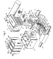
- Figure 1 shows in an exploded perspective view a carriage and surrounding parts in a wire dot printer adapted to use a plurality of differently coloured inks according to the present invention.
- a carriage 20 supports thereon ink tanks 50a, 50b, 50c for containing inks of three colours, that is, cyan, yellow and magenta.
- the carriage 20 also supports a tube pump 90, and a print head 1.
- the carriage 20 is movable transversely across a sheet of recording paper (not shown).
- the print head 1 comprises a nose 3 housing a total of twenty four printing wires 14 ( Figure 2) and a driver 2 for selectively projecting the wires 14 toward 'the sheet of recording paper.
- the print head 1 is secured to the carriage 20 by screws 24.
- the wires 14 are guided by and supplied with inks from a guide block 4.
- the guide block 4 has an ink supply and discharge guide 5 to which a tube connector 13 is coupled.
- Figure 2 is a cross-sectional view of the nose 3 showing the guide block 4 and the tube connector 13.
- the guide block 4 is in the form of a hollow prism extending longitudinally of the wires 14, and has two partitions 4a (Figure 1) extending in the longitudinal direction of the wires 14 to divide the guide block 4 into three compartments 4b ( Figure 1).
- the ink supply and discharge guide 5 is mounted integrally on the front end of the guide block 4. As many guide plates 19a, 19b, 19c as are required for preventing the wires 14 from buckling are disposed in the guide block 4.
- the wires 14 are inserted from the left ( Figure 2) where the driver 2 is located through guide holes 19d in the guide plates 19a, 19b, 19c and guide holes in the ink supply and discharge guide 5 until the wire ends reach the printing end at the right of Figure 2.
- Three ink application guides 7 and three wire guides 6 are mounted on the guide block 4 for controlling the amount of ink applied and for arranging the wires 14 properly, as more fully described below.
- the print head 1 has twenty four wires 14 divided into three groups of eight wires, each group being constituted by a vertical row or array of wires and being housed in a respective wire guide 6 and ink application guide 7 so as to be supplied with an ink of one particular colour which differs from that of the other groups.
- the groups of wires 14 are separated by the partitions 4a and are each arranged in a vertical array at the printing end, i.e. the distal end of the print head 1.
- the twenty four wires 14 are positioned at the nose end in three vertical arrays of wire ends or printing end faces 14a (see Figure 4) which are separated from each other.
- the inks are supplied through ink supply holes 8 in a lower portion of the ink supply and discharge guide 5, and circulate through the ink supply and discharge guide 5. Portions of the ink supply are fed to the wires 14 and are used up in the printing, and any excess ink is collected through ink collection holes 9 formed above the ink supply holes 8 in the lower portion of the ink supply and discharge guide 5. Since the wires 14 for each ink colour are vertically arrayed, three respective ink passages may be formed independently of each other in the respective ink application guides 7. During the printing operation, the inks are transferred back along the wires due to reciprocating movement thereof. However, there is no danger that these inks may get mixed together as the compartments 4b in the guide block 4 are separated by the partitions 4a.
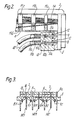
- FIG 3 shows in cross-section an ink applicator assembly at the distal end of the print head shown in Figure 1.
- the ink applicator assembly comprises the ink supply and discharge guide 5, the wire guides 6, and the ink application guides 7.
- the ink applicator assembly is composed of three ink applicator devices juxtaposed laterally, each ink applicator device being basically as disclosed in the co-pending European Patent Application Serial No. 81302692.9 entitled "Wire dot printer".
- the inks having the colours of yellow, magenta and cyan be represented by Y, M, C, respectively.
- the inks Y, M, C are passed through ink supply ports 8Y, 8M, 8C, respectively, and ink passages to ink collection ports 9Y, 9M, 9C, respectively.
- the ink passages are defined between the ink supply and discharge guide 5 and the wire guide 6.
- the wires 14 are arranged as wire arrays 14Y, 14M, 14C in the respective ink applicator devices 6, 7.
- the inks are stably applied to the wire arrays by the respective ink application guides 7. More specifically, each ink passage comprises a by-pass portion 15 having an increased depth and width for allowing ink to flow easily, and a capillary region 16 defined in a reduced gap between the ink supply guide 5 and the wire guide 6 for drawing ink due to capillary attraction.
- each wire guide 6 and the respective wires 14 are spaced by clearances dimensioned to provide capillary attraction. The inks are thus fed toward the wire ends 14a and applied thereto under the capillary attraction of the capillary region 16 and pumping action when the wires 14 are driven longitudinally.
- Figure 4 is a perspective view of the guide block 4 showing the wire ends 14a, with the ink application guides 7 and the wire guides 6 removed. As shown, the partitions 4a extend to the printing end of the guide block 4, for thereby preventing the coloured inks from being mixed together at the printing end beyond the ink supply and discharge guide 5, so as to establish clear colour printing.
- Figure 5 is a front elevational view of the guide block 4 illustrating the printing ends 14a of the wires 14.
- the respective ink application guide 7 is shown mounted on the right-hand wire array.
- the respective ink application guide 7 is not shown in the case of the central wire array.
- Neither the respective ink application guide 7 nor the respective wire guide 6 are shown in the case of the left-hand wire array so that the ink supply and discharge guide 5 can be clearly seen.
- the inks supplied from the ink supply ports 8 flow into the by-pass portions 15, then are drawn into the capillary regions 16, and are finally discharged through the ink collection ports 9.
- Each ink application guide 7 has a plurality of slots 7b leading to wire guide holes 7a for guiding the respective wires 14, and a slot 7c connecting the wire guide holes 7a together for allowing smooth application of ink to the respective wires 14. While each ink applicator device has been described as being composed of separate components, that is the wire guide 6, and the ink application guide 7, the wire guide 6 and the ink application guide 7 may be integrally formed.
- Figure 6 is a bottom view of the nose 3 of the print head 1, the view showing the guide block 4 for guiding the wires 14 and supplying the inks to the wires 14.
- the ink supply and discharge guide 5 constitutes part of the guide block 4, and the tube connector 13 is coupled to the ink supply and discharge guide 5.
- a total of six tubes 40 which are respectively referenced 40a to 40f, for supplying and discharging the inks of the respective colours are connected to the tube connector 13 and to the ink tanks 50a, 50b, 50c through the pump 90.
- the tube connector 13 is slidably set in place between carriage members 20a, 20b, and the head 1 or the tube connector 13 or both are slidably positioned relative to each other to permit six projections 5a of the ink supply and discharge guide 5, which projections 5a are provided with the holes 8, 9, to be connected in a corresponding six holes, such as 10a, 10b of the tube connector 13, for setting the print head 1 in position.
- the head 1 is fastened to the carriage 20 by the screws 24. Accordingly, the head 1 can be quite easily secured to the carriage 20 with the tubes 40 connected to the head 1.
- the holes 10a, 10b in the tube connector 13 are coupled to the projections 5a of the ink supply and discharge guide 5.
- the tube connector 13 has grooves receiving O-rings 12 therein for preventing ink leakage and allowing more reliable tub connection.
- the O-rings 12 may alternatively be received in the projectione 5a of the ink supply and discharge guide 5 for the same reason.
- the ink tanks and the pump for supplying and discharging the inks will now be described with reference to Figure 1.
- the ink tanks 50a, 50b, 50c are removably mounted in a tank guide 51 fixed to the carriage 20.
- Hollow needles 52 are disposed in and affixed to the tank guide 51 for passing the inks from the tanks 50a, 50b, 50c and for introducing the inks into the tanks 50a, 50b, 50c.
- the ink tanks 50a, 50b, 50c with the inks of three colours, that is, cyan, yellow, and magenta are mounted in the tank guide 51 for effecting multi-colour printing.
- the tank guide 51 has partitions 51d extending to the bottom thereof and defining independent tank insertion compartments 51a, 51b, 51c respectively for the ink tanks 50a, 50b, 50c.
- the hollow needles 52 are provided in pairs, each said pair corresponding to one colour only. With the three colours in this embodiment, a total of six hollow needles are secured to the bottom of the tank guide 51.
- the ink tanks 50a, 50b, 50c are inserted respectively in the tank insertion compartments 51a, 51b, 51c. When the ink tanks are fully inserted, the hollow needles 52 penetrate resilient diaphragms (not shown) attached to the bottoms of the inktanks for supplying the inks contained in the ink tanks.
- tank compartments 51a, 51b, 51c are divided independently by the partitions 51d d extending to the bottom of the ink tank 51, there is no risk that the inks of the different colours may become mixed together even when there is ink leakage upon attachment or removal of the ink tanks. Therefore, proper multicolour printing can be achieved at all times.
- the pump 90 for supplying the inks is in the form of a tube pump driven by a pump motor 30 through a motor gear 31, intermediate gears 32, 33, and a pump gear 34.
- the pump motor 30 is secured to a projection 20f of the carriage 20 by screws 39 (only one shown).
- An intermediate gear shaft 35 is screwed to or mounted by insert moulding on a carriage projection 20e.
- an intermediate gear shaft 37 and a pump gear shaft 36 are screwed to or mounted by insert moulding on carriage projections 20c, 20d.
- the tubes 40 which are made of an elastomeric material such as silicone rubber, extend from the hollow needles 52, which project into the ink tanks 50a, 50b, 50c and extend through the tube pump 90 to the tube connector 13 and thus to the ink supply and discharge guide 5 which is integral with the print head 1. Therefore, ink paths are formed which extend from the ink tanks 50a, 50b, 50c to the tube pump 90 and 50 to the print head 1, and then back to the tube pump 90 and to the ink tanks 50a, 50b, 50c.
- an elastomeric material such as silicone rubber
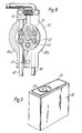
- the pump 90 will next be described in greater detail with reference to Figures 7 and 8.
- the pump 90 is a peristaltic pump having tube presser rollers 44 ( Figure 8) for application to the tubes 40, the tube presser rollers 44 being mounted respectively on roller shafts 43.
- the pump 90 is supported on the pump gear shaft 36 which is provided with the pump gear 34, the pump gear shaft 36 being journalled in a bearing plate 41.
- the tubes 40 extend through holes in a pump housing 38, the said holes being slightly smaller in diameter than the tubes 40.
- the tubes 40 are fixed in these holes against withdrawal under frictional forces.
- the housing 38 is composed of a pair of housing members 38a, 38b pivotably mounted on the intermediate gear shaft 37 and urged by a spring 42 extending therebetween to press the tubes 40.
- the principles of operation of the tube pump 90 are known and hence will not be described in detail.
- the pump gear 34 When the pump motor 30 is energized, the pump gear 34 is driven to cause the tube presser rollers 44 arranged in a circle concentric with the pump gear 34 to rotate about the roller shafts 43 and also to revolve around the pump gear shaft 36.
- the tube presser rollers 44 as they roll along press the tubes 40 against the housing members 38a, 38b to effect peristaltic pumping of the fluids or inks in the tubes.
- two tubes 40 are provided for supplying and discharging an ink of a single colour, and hence a total of six tubes 40a to 40f are provided for printing in three colours.
- the tubes are disposed in three adjacent pairs between the housing members 38a, 38b.
- the pump 90 can thus be of a small size for feeding and discharging the inks of the three colours.
- the illustrated embodiment employs a tube pump, pumps of other types such as a gear pump or a plunger pump may be employed in place of the tube pump.
- Figure 9 is a diagrammatic perspective view of an ink tank 50 which may be used in a wire dot printer according to an embodiment of the present invention, the ink tank 50 having a manually engageable grip 54 affixed thereto by means of a grip fastening pin 53.
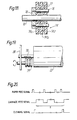
- Figure 10 shows the grip 54 in plan at (a) and in cross section at (b).
- the grip 54 should preferably be of a flexibly resilient material such as rubber.
- the grip 54 shown in Figure 10 is basically comprised of a grip portion 54a to be gripped by hand and an engagement portion 54c to be held in engagement with the ink tank 50.
- the engagement portion 54c includes a bulb-shaped body 54d having a central hole 54b extending therethrough and including a conical taper portion 54e at a lower end thereof.
- FIG 11 illustrates in cross-section the grip 54 as attached to the ink tank 50.
- the ink tank 50 is made of a plastics material such as polyacetal or nylon, and has a hole 50d in its upper wall 50e for insertion therein of the engagement portion 54c of the grip 54.
- the ink tank 50 also has in its lower wall 50f a hole 50g in which there is inserted a resilient diaphragm 55.
- An ink supply needle 52a for supplying ink from the tank 50 to the tubes 40, and an ink return needle 52b, for returning excess ink to °the tank 50, extend through the resilient diaphragm 55 and into the tank 50.
- the ink supply needle 52a and the ink return needle 52b are mounted on the tank guide (not shown in Figure 11) and have pointed distal ends.
- the needles 52a, 52b can penetrate the resilient diaphragm 55 on the bottom of the ink tank 50 so that ink can be supplied from the ink tank or returned to the ink tank.
- the resilient diaphragm 55 may be formed of rubber, for example, to provide sealing against ink leakage.
- the engagement portion 54c of the grip 54 is pushed into the hole 50d in the upper wall 50e of the ink tank 50, and the grip fastening pin 56 is then inserted into the hole in the engagement portion 54c. Since the hole 54b in the engagement portion 54c is tapered as shown in Figure 10(b) prior to the engagement portion 54c being pushed into the hole 50d, the bulb-shaped body 54d of the engagement portion 54c is spread outwardly by pushing a pin 56 of a substantially uniform cross section into the hole 54b. Therefore, the engagement portion 54c is secured to the ink tank 50 to prevent it from being pulled off when the plate-shaped grip 54a is gripped and pulled up in order to remove the ink tank 50 from the tank guide.
- the grip fastening pin 56 has a vertical through aperture 56a effective in allowing air to escape out of the ink tank 50.
- the pump 90 has a greater ability to collect ink from the head than to supply ink to the head for stabilizing the printing quality. For this reason, ink and excess air are introduced into the ink tank 50. If the ink tank 50 were sealed off, the pressure within the ink tank 50 would be increased to the point where some damage could occur.
- the aperture 56a in the pin 56 for allowing air escape is thus required for preventing this shortcoming.
- the grip may have a ring shaped handle portion 57 as shown in Figure 12(a), a rod shaped handle portion 58 as shown in Figure 12(b), or any other simple configuration which provides an easy grip.
- the ink tank 50 With the grip 54 mounted on the ink tank 50, the ink tank 50 can easily be removed simply by gripping and pulling up the grip 54 when desired. There is no need to change the dimensions of the contour of the ink tank 50 for such removal.
- the ink tank 50 can be removed with no space available around the inktank. Where a plurality of such ink tanks are disposed in juxtaposed relation as illustrated in Figure 1, it would be quite difficult to hold the ink tanks themselves by hand, but they can readily be detached by gripping the grips described above. Since a plurality of inks having varying colours are utilized in multicolour printers, it is necessary that the colours of the inks in the ink tanks be identified when the ink tanks are to be inserted or replaced.
- the grips 54a, 54b, 54c are differently coloured in hues corresponding respectively to the inks.
- the colours used can be identified with the utmost ease.
- the grips are made of rubber, they may be given any desired colour by mixing one or more pigments with the rubber. Accordingly, ink tank identification can be accomplished simply and inexpensively.
- Another advantage with the present invention is that it is easy to introduce ink into an ink tank. Before the grip 54 is mounted on the ink tank 50, the relatively large hole 50d remains open in the upper wall 50e of the ink tank 50, and the ink can be introduced into the ink tank through this hole 50d.
- the grip 54 is attached and the grip fastening pin 56 is pushed in.
- the bulb-shaped body 54d of the engagement portion 54c of the grip 54 is easily deformable, so that the engagement portion 54c can easily be fitted into the ink tank 50 with no danger that any of the ink therein will be ejected from the ink tank.
- the inks Y, M, C are supplied from the independent ink tanks 54a, 54b, 54c through the respective tubes 40 to the ink supply and discharge guide 5 on the distal end of the print head 1. Excess inks are returned to the respective ink tanks.
- the print head of the said wire dot printer has a respective wire array for each of the different colours, the wire arrays constituting, in effect, independent print heads. Therefore, the fundamental colours Y, M, C can bs simultaneously printed when the print head moves over a sheet of recording paper in a single stroke.
- Figure 13 shows an arrangement of wire ends 14a at the distal end of the print head 1.
- the wire arrays 14Y, 14M, 14C have the same number of wires positioned at the same height.
- the print head 1 is controlled to print dots on the next wire array.
- This mode of operation allows any of the colours Y, M, C to be printed on any single point on the recording paper.
- a dot can be printed in red.
- dots can be printed in blue and green by superimposing the colours M and C, and Y and C, respectively.
- a black dot can be printed by superimposing the colours Y, M, C. Accordingly, seven colours can be obtained simply by moving the print head over the recording paper in a single stroke.
- Figure 14 shows another embodiment of a multicolour printing operation in which dots 17Y, 17M, 17C in the colours Y, M, C, respectively, are printed so as not to be superimposed, and three adjacent dots in the colours Y, M, C are regarded as a single picture element or pixel (18). With this arrangement, seven colours can be printed by suitably combining the dots in Y, M, C in the pixels. It is important for clear hue expression with this multicolour printing system that wires of small diameters be used for printing small dots to reduce the diameter of the pixels.
- the small diameter wires tend to pierce through interstices in the ribbon fabric, resulting in damage to the ink ribbon.
- the smaller wire diameter which can be used contributes to improved printing quality and is capable of easy hue expression with dot matrices.
- Multicolour printers using ink ribbons are disadvantageous in that the ink density on the ribbon varies due to the differences between the frequency of use of the different colour areas on the ribbon, resulting in the printing of unbalanced colours.
- wire dot printers utilizing inks liquid inks are directly applied to the wire ends so that no change occurs in the colour density and hence the printed colours are balanced even after printing has been carried out for a long period of time.
- a cleaning device for removing paper dust and ink deposited on the distal end of the print head will now be described.
- the print head for multicolour printing has wire arrays 14Y, 14M, 14C containing equal numbers of wires and spaced at equal distances L.
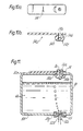
- Figure 15 fragmentarily shows a printer having a cleaning devica
- Figure 16 is a side elevational view of the printer shown in Figure 15.
- Th print head 1 is reciprocated in the directions of the arrows by a drive mechanism (not shown) for printing on a sheet of recording paper (not shown) on a platen 23.
- a cleaning member 71 comprises an integral body having a stepped configuration as illustrated in Figure 15 and including cleaning portions 71a, 71b, 71c having centres spaced at a distance L equal to the distance L at which the wire arrays are spaced apart.
- the cleaning member 71 is rotatably mounted on a platen shaft 70 which is coaxial with the platen 23.
- the cleaning member 71 is made of a porous, water-absorbent, resilient spongy material such as a foamed polyvinyl formal resin.
- the density of minute holes in the cleaning member 71 is rendered progressively higher from the outer periphery toward the centre of the cleaning member 71 so that the water absorption capability becomes stronger toward the centre of the cleaning member 71. This enables inks to flow more easily toward the centre of the cleaning member 71 and tends to prevent inks from mixing at the outer periphery of the latter.
- the cleaning member 71 is of an integral construction and can be rotated independently of the motion of the platen 23 by a drive mechanism (not shown) which may comprise a motor, a solenoid, or the like.
- the outer peripheral configuration of the cleaning member 71 comprises projections 72 which can be held in contact with a distal end 1a of the print head 1 and alternate recesses 73 which are at all times held out of engagement with the distal end 1a of the print head 1.
- the cleaning member 71 has a radius R at the projections 72, the radius R being slightly larger than the distance between the centre of the platen 23 and the distal end la of the print head 1 by a distance which may range from 0.1 to 0.2 mm, for example.
- the distal end 1 a of the print head 1 can be brought into complete oontact with the cleaning member 71 at the projections 72.
- the cleaning member 71 is, however, always kept out of contact with the print head end 1a at the recesses 73.
- the print head 1 Afterthe print head 1 has printed desired characters and symbols while reciprocating in the directions of the arrows of Figure 15, the print head 1 returns to and stops in its home position in which the cleaning portions 71 a, 71 b, 71 face the wire arrays 14Y, 14M, 14C, respectively. At this time, the cleaning member 71 is stopped with one of the recesses 73 facing the distal end 1a of the print head 1 as illustrated in Figure 16. Then the cleaning member 71 is rotated by its drive mechanism (not shown) to cause one of the projections 72 to wipe the print head end 1 a so as to remove paper dust, ink and other foreign matter. When the next recess 73 faces the print head end 1a, the rotation of the cleaning member 71 is brought to an end, and the print head 1 is actuated for a next cycle of the printing operation.
- the portions of the print head end 1a respectively for the different inks can be cleaned independently, so that no ink mixture will take place on the print head.
- Figure 17 is a side elevational view of another embodiment of a cleaning member which may be used in the wire dot printer of the present invention
- Figure 18 is a cross-sectional view of the cleaning member of Figure 17 as mounted on a platen shaft.
- a cleaning member 74 includes three cleaning portions 74a, 74b, 74c corresponding to the three ink colours used.
- the outer peripheral shape of the cleaning member 74 is the same as that of the cleaning member 71 illustrated in Figure 16. However, as shown in Figure 17, the cleaning member 74 is divided into two cleaning member pieces 74-1, 74-2 having attachment holes 75.
- the cleaning member 74 is rotatably mounted coaxially on the platen shaft 70.
- the cleaning member 74 is secured to an attachment plate 78 by attachment pins 76 which pass through the attachment holes 75, the attachment plate 78 being rotatably mounted on the platen shaft 70.
- the cleaning portions 74a, 74b, 74c are divided by partitions 77 so as to prevent ink mixture between the cleaning portions. Since the cleaning member 74 is divided into the cleaning member pieces 74-1, 74-2, it can easily be attached to and detached from the attachment plate 78 for replacement when the cleaning member 74 is smeared with ink or is damaged or worn out.
- the use of the partitions 77 helps to prevent inks from being mixed together between the cleaning portions.
- Figure 19 illustrates yet another embodiment of a cleaning member which may be used in a wire dot printer according to the present invention.
- the cleaning member 79 shown in Figure 19 has the same outer peripheral shape as those of the cleaning members of the previous embodiments, it is mounted on a frame 80 out of axial alignment with the platen 70 and independently thereof so that its axial position may be adjusted.
- the cleaning member 79 is rotatable in the directions of the arrows. With this arrangement, the distance between the cleaning member 79, and the distal end 1a of the print head 1 can easily be adjusted, and the cleaning member 79 can be removed from or attached to the printer more simply for easy replacement without requiring the removal or attachment of other parts.
- the cleaning member 79 may be of an integral construction with grooves between adjacent cleaning portions as shown in Figure 15, or may have as many cleaning portions as there are colours to be printed with partitions interposed therebetween.
- Figure 20 is a timing chart showing operation of the cleaning device.
- the sheet of recording paper is fed along by each paper feed signal, and the print head 1 is moved in one direction of reciprocation at each carriage feed signal. After the print head 1 has returned to the home position, the cleaning member is rotated by a cleaning signal to clean the distal end 1a a of the print head 1.
- the cleaning signal can also be generated by manual operation. As long as the print head 1 is stopped in the home position with the cleaning portions 71a, 71b, 71c facing the wire arrays 14Y, 14M, 14c, respectively, a cleaning signal can be issued as desired to rotate the cleaning member 71 for cleaning the distal end 1 a of the print head 1.
- the home position may not necessarily be aligned with the cleaning member. Instead, the print head may be moved to bring its wire arrays opposite to the cleaning portions of the cleaning member in response to a cleaning signal, and after the print head has come to a stop, the cleaning member may be rotated for the cleaning operation.
Landscapes
- Ink Jet (AREA)
Claims (10)
Applications Claiming Priority (8)
| Application Number | Priority Date | Filing Date | Title |
|---|---|---|---|
| JP8377182A JPS58201672A (ja) | 1982-05-18 | 1982-05-18 | インク式ワイヤドツトプリンタのヘツド |
| JP83772/82 | 1982-05-18 | ||
| JP83771/82 | 1982-05-18 | ||
| JP8377282A JPS58201673A (ja) | 1982-05-18 | 1982-05-18 | カラ−インク式ワイヤドツトプリンタのヘツド |
| JP87806/82 | 1982-05-24 | ||
| JP57087806A JPS58205777A (ja) | 1982-05-24 | 1982-05-24 | インク式ワイヤドツトプリンタの清掃装置 |
| JP8780582A JPS58205776A (ja) | 1982-05-24 | 1982-05-24 | インク式ワイヤドツトプリンタの印字ヘツド |
| JP87805/82 | 1982-05-24 |
Publications (3)
| Publication Number | Publication Date |
|---|---|
| EP0094798A2 EP0094798A2 (de) | 1983-11-23 |
| EP0094798A3 EP0094798A3 (en) | 1985-04-10 |
| EP0094798B1 true EP0094798B1 (de) | 1988-08-10 |
Family
ID=27466876
Family Applications (1)
| Application Number | Title | Priority Date | Filing Date |
|---|---|---|---|
| EP83302702A Expired EP0094798B1 (de) | 1982-05-18 | 1983-05-12 | Nadelpunktdrucker zur Verwendung mit einer Vielzahl verschiedener farbiger Tinten |
Country Status (5)
| Country | Link |
|---|---|
| US (1) | US4579468A (de) |
| EP (1) | EP0094798B1 (de) |
| DE (1) | DE3377632D1 (de) |
| HK (1) | HK30891A (de) |
| SG (1) | SG59790G (de) |
Families Citing this family (10)
| Publication number | Priority date | Publication date | Assignee | Title |
|---|---|---|---|---|
| US5328279A (en) * | 1984-05-22 | 1994-07-12 | Seiko Epson Corporation | Dot matrix printer head |
| US5156470A (en) * | 1983-10-13 | 1992-10-20 | Seiko Epson Corporation | Two cartridge ink-supply system for a multi-color dot matrix printer |
| US5156473A (en) * | 1983-10-13 | 1992-10-20 | Seiko Epson Corporation | Multi-color cartridge ink-supply system for a dot matrix printer |
| JPS62105698A (ja) * | 1985-11-05 | 1987-05-16 | ソニー株式会社 | プリンタ |
| US4829318A (en) * | 1987-09-30 | 1989-05-09 | Dataproducts, Inc. | Head tending system for purging and cleaning an ink jet print head |
| US5197043A (en) * | 1991-03-29 | 1993-03-23 | Strader Verne A | Night and day earth clock calendar |
| US6749293B1 (en) | 2001-06-13 | 2004-06-15 | Nu-Kote International, Inc. | Full liquid version of ink jet cassette for use with ink jet printer |
| US6682183B2 (en) | 2001-06-13 | 2004-01-27 | Nu-Kote International, Inc. | Seal member for ink jet cartridge |
| US6814433B2 (en) * | 2001-06-13 | 2004-11-09 | Nu-Kote International, Inc. | Base aperture in ink jet cartridge with irregular edges for breaking surface tension of the ink |
| US6923530B2 (en) * | 2001-06-13 | 2005-08-02 | Nu-Kote International, Inc. | Fused filter screen for use in ink jet cartridge and method of assembling same |
Family Cites Families (8)
| Publication number | Priority date | Publication date | Assignee | Title |
|---|---|---|---|---|
| DE867997C (de) * | 1950-09-02 | 1953-02-23 | August Zehnder | Typenreiniger fuer Bueromaschinen |
| US3858703A (en) * | 1973-01-05 | 1975-01-07 | Centronics Data Computer | Bidirectional dual head printer |
| DE2546835C3 (de) * | 1975-10-18 | 1980-11-06 | Philips Patentverwaltung Gmbh, 2000 Hamburg | Druckeinrichtung mit in Längsrichtung verschiebbaren Drucknadeln |
| US4194846A (en) * | 1978-04-28 | 1980-03-25 | Centronics Data Computer Corp. | Dot matrix printing device employing a novel image transfer technique to print on single or multiple ply print receiving materials |
| JPS5561490A (en) * | 1978-11-01 | 1980-05-09 | Ricoh Co Ltd | Cleaning apparatus for image scanning recording head |
| JPS5633972A (en) * | 1979-08-28 | 1981-04-04 | Nippon Telegr & Teleph Corp <Ntt> | Color printer |
| DE3174800D1 (en) * | 1980-06-17 | 1986-07-24 | Seiko Epson Corp | A wire dot printer |
| US4343007A (en) * | 1980-09-26 | 1982-08-03 | Honeywell Inc. | Multi-color multi-point recorder |
-
1983
- 1983-05-12 DE DE8383302702T patent/DE3377632D1/de not_active Expired
- 1983-05-12 EP EP83302702A patent/EP0094798B1/de not_active Expired
-
1985
- 1985-09-24 US US06/780,230 patent/US4579468A/en not_active Expired - Lifetime
-
1990
- 1990-07-19 SG SG597/90A patent/SG59790G/en unknown
-
1991
- 1991-04-18 HK HK308/91A patent/HK30891A/xx not_active IP Right Cessation
Also Published As
| Publication number | Publication date |
|---|---|
| SG59790G (en) | 1990-09-07 |
| EP0094798A2 (de) | 1983-11-23 |
| HK30891A (en) | 1991-04-26 |
| US4579468A (en) | 1986-04-01 |
| EP0094798A3 (en) | 1985-04-10 |
| DE3377632D1 (en) | 1988-09-15 |
Similar Documents
| Publication | Publication Date | Title |
|---|---|---|
| EP0094798B1 (de) | Nadelpunktdrucker zur Verwendung mit einer Vielzahl verschiedener farbiger Tinten | |
| EP0054694B1 (de) | Für einen Tintenstrahldrucker mit einem entlang der Druckzeile hin und her bewegbaren Druckwagen bestimmter Druckkopf | |
| US11084290B2 (en) | Liquid ejecting apparatus | |
| DE69233485T2 (de) | Hostgerät, das mit einem Aufzeichnungsgerät über eine Signalliefereinrichtung verbindbar ist. | |
| DE60210459T2 (de) | Tintenstrahldrucker | |
| US6176629B1 (en) | Ink supply tank for a printer | |
| EP1405725B1 (de) | Wartungsverfahren für einen Tintenstrahldruckkopf | |
| DE3316474C2 (de) | ||
| DE60300337T2 (de) | Tintenbehälter, Aufzeichnungskopf und Aufzeichnungsgerät mit einem solchen Behälter | |
| US5485188A (en) | Ink jet recording method employing inks, ink set, and apparatus for use with the inks | |
| DE69628678T2 (de) | Aufzeichnungsapparat mit Schwingrahmen | |
| EP0139238B1 (de) | Drahtpunktdrucker | |
| EP0732211A1 (de) | Unabhängige Reinigungsstationen für mehrere Druckköpfe in Tintenstrahldruckern | |
| EP1870241A1 (de) | Bilderzeugungsvorrichtung und Ansteuerverfahren dafür | |
| US5156473A (en) | Multi-color cartridge ink-supply system for a dot matrix printer | |
| US5221148A (en) | Dot matrix printer ink supply system having ink absorbing member substantially filling an ink tank | |
| EP0749837A1 (de) | Anordnung zur Reinhaltung der Düsen eines Tintendruckkopfes | |
| US5461405A (en) | Ink jet printer device with exchangeable printheads | |
| DE60224601T2 (de) | Flüssigkeitsausstosskopf, Instandsetzungsverfahren durch saugen, Kopfkassette und Bilderzeugungsgerät | |
| EP0730965B1 (de) | Linear bewegender Wischer für einen Tintenstrahldruckkopf | |
| US5174665A (en) | Ink-supply system for a dot matrix printer | |
| DE60126020T2 (de) | Aufzeichnungskopf mit Flüssigkeitsausstoss und Aufzeichnungsgerät | |
| US5943071A (en) | Wiper blade cleaning system for nozzle faces of a color printhead | |
| KR20060044420A (ko) | 잉크 젯 기록 장치 | |
| DE19733152B4 (de) | Ersetzbarer Tintenbehälter zur Verwendung in einem Drucker und Tintenstrahldrucksystem |
Legal Events
| Date | Code | Title | Description |
|---|---|---|---|
| PUAI | Public reference made under article 153(3) epc to a published international application that has entered the european phase |
Free format text: ORIGINAL CODE: 0009012 |
|
| AK | Designated contracting states |
Designated state(s): DE FR GB IT NL |
|
| PUAL | Search report despatched |
Free format text: ORIGINAL CODE: 0009013 |
|
| AK | Designated contracting states |
Designated state(s): DE FR GB IT NL |
|
| 17P | Request for examination filed |
Effective date: 19850913 |
|
| RAP1 | Party data changed (applicant data changed or rights of an application transferred) |
Owner name: SEIKO EPSON CORPORATION |
|
| 17Q | First examination report despatched |
Effective date: 19870213 |
|
| GRAA | (expected) grant |
Free format text: ORIGINAL CODE: 0009210 |
|
| AK | Designated contracting states |
Kind code of ref document: B1 Designated state(s): DE FR GB IT NL |
|
| PG25 | Lapsed in a contracting state [announced via postgrant information from national office to epo] |
Ref country code: NL Effective date: 19880810 Ref country code: IT Free format text: LAPSE BECAUSE OF FAILURE TO SUBMIT A TRANSLATION OF THE DESCRIPTION OR TO PAY THE FEE WITHIN THE PRESCRIBED TIME-LIMIT;WARNING: LAPSES OF ITALIAN PATENTS WITH EFFECTIVE DATE BEFORE 2007 MAY HAVE OCCURRED AT ANY TIME BEFORE 2007. THE CORRECT EFFECTIVE DATE MAY BE DIFFERENT FROM THE ONE RECORDED. Effective date: 19880810 |
|
| REF | Corresponds to: |
Ref document number: 3377632 Country of ref document: DE Date of ref document: 19880915 |
|
| ET | Fr: translation filed | ||
| NLV1 | Nl: lapsed or annulled due to failure to fulfill the requirements of art. 29p and 29m of the patents act | ||
| PLBE | No opposition filed within time limit |
Free format text: ORIGINAL CODE: 0009261 |
|
| STAA | Information on the status of an ep patent application or granted ep patent |
Free format text: STATUS: NO OPPOSITION FILED WITHIN TIME LIMIT |
|
| 26N | No opposition filed | ||
| PGFP | Annual fee paid to national office [announced via postgrant information from national office to epo] |
Ref country code: GB Payment date: 19980505 Year of fee payment: 16 |
|
| PGFP | Annual fee paid to national office [announced via postgrant information from national office to epo] |
Ref country code: FR Payment date: 19980511 Year of fee payment: 16 |
|
| PGFP | Annual fee paid to national office [announced via postgrant information from national office to epo] |
Ref country code: DE Payment date: 19980515 Year of fee payment: 16 |
|
| PG25 | Lapsed in a contracting state [announced via postgrant information from national office to epo] |
Ref country code: GB Free format text: LAPSE BECAUSE OF NON-PAYMENT OF DUE FEES Effective date: 19990512 |
|
| GBPC | Gb: european patent ceased through non-payment of renewal fee |
Effective date: 19990512 |
|
| PG25 | Lapsed in a contracting state [announced via postgrant information from national office to epo] |
Ref country code: FR Free format text: LAPSE BECAUSE OF NON-PAYMENT OF DUE FEES Effective date: 20000131 |
|
| PG25 | Lapsed in a contracting state [announced via postgrant information from national office to epo] |
Ref country code: DE Free format text: LAPSE BECAUSE OF NON-PAYMENT OF DUE FEES Effective date: 20000301 |
|
| REG | Reference to a national code |
Ref country code: FR Ref legal event code: ST |