EP0094736B1 - Disc brakes - Google Patents
Disc brakes Download PDFInfo
- Publication number
- EP0094736B1 EP0094736B1 EP19830301559 EP83301559A EP0094736B1 EP 0094736 B1 EP0094736 B1 EP 0094736B1 EP 19830301559 EP19830301559 EP 19830301559 EP 83301559 A EP83301559 A EP 83301559A EP 0094736 B1 EP0094736 B1 EP 0094736B1
- Authority
- EP
- European Patent Office
- Prior art keywords
- support
- disc
- pads
- spring
- arm
- Prior art date
- Legal status (The legal status is an assumption and is not a legal conclusion. Google has not performed a legal analysis and makes no representation as to the accuracy of the status listed.)
- Expired
Links
- 229910001220 stainless steel Inorganic materials 0.000 description 4
- 239000010935 stainless steel Substances 0.000 description 4
- XAGFODPZIPBFFR-UHFFFAOYSA-N aluminium Chemical compound [Al] XAGFODPZIPBFFR-UHFFFAOYSA-N 0.000 description 3
- 229910052782 aluminium Inorganic materials 0.000 description 3
- 239000004411 aluminium Substances 0.000 description 3
- 238000009434 installation Methods 0.000 description 3
- 241001247986 Calotropis procera Species 0.000 description 2
- 229910001209 Low-carbon steel Inorganic materials 0.000 description 2
- 238000006243 chemical reaction Methods 0.000 description 2
- 229920000181 Ethylene propylene rubber Polymers 0.000 description 1
- 241000357293 Leptobrama muelleri Species 0.000 description 1
- 238000010276 construction Methods 0.000 description 1
- 238000006056 electrooxidation reaction Methods 0.000 description 1
- 239000002783 friction material Substances 0.000 description 1
- 238000007689 inspection Methods 0.000 description 1
Images

Classifications
-
- F—MECHANICAL ENGINEERING; LIGHTING; HEATING; WEAPONS; BLASTING
- F16—ENGINEERING ELEMENTS AND UNITS; GENERAL MEASURES FOR PRODUCING AND MAINTAINING EFFECTIVE FUNCTIONING OF MACHINES OR INSTALLATIONS; THERMAL INSULATION IN GENERAL
- F16D—COUPLINGS FOR TRANSMITTING ROTATION; CLUTCHES; BRAKES
- F16D65/00—Parts or details
- F16D65/02—Braking members; Mounting thereof
- F16D65/04—Bands, shoes or pads; Pivots or supporting members therefor
- F16D65/092—Bands, shoes or pads; Pivots or supporting members therefor for axially-engaging brakes, e.g. disc brakes
- F16D65/095—Pivots or supporting members therefor
- F16D65/097—Resilient means interposed between pads and supporting members or other brake parts
- F16D65/0973—Resilient means interposed between pads and supporting members or other brake parts not subjected to brake forces
- F16D65/0974—Resilient means interposed between pads and supporting members or other brake parts not subjected to brake forces acting on or in the vicinity of the pad rim in a direction substantially transverse to the brake disc axis
- F16D65/0977—Springs made from sheet metal
-
- F—MECHANICAL ENGINEERING; LIGHTING; HEATING; WEAPONS; BLASTING
- F16—ENGINEERING ELEMENTS AND UNITS; GENERAL MEASURES FOR PRODUCING AND MAINTAINING EFFECTIVE FUNCTIONING OF MACHINES OR INSTALLATIONS; THERMAL INSULATION IN GENERAL
- F16D—COUPLINGS FOR TRANSMITTING ROTATION; CLUTCHES; BRAKES
- F16D55/00—Brakes with substantially-radial braking surfaces pressed together in axial direction, e.g. disc brakes
- F16D55/02—Brakes with substantially-radial braking surfaces pressed together in axial direction, e.g. disc brakes with axially-movable discs or pads pressed against axially-located rotating members
- F16D55/22—Brakes with substantially-radial braking surfaces pressed together in axial direction, e.g. disc brakes with axially-movable discs or pads pressed against axially-located rotating members by clamping an axially-located rotating disc between movable braking members, e.g. movable brake discs or brake pads
- F16D55/224—Brakes with substantially-radial braking surfaces pressed together in axial direction, e.g. disc brakes with axially-movable discs or pads pressed against axially-located rotating members by clamping an axially-located rotating disc between movable braking members, e.g. movable brake discs or brake pads with a common actuating member for the braking members
- F16D55/225—Brakes with substantially-radial braking surfaces pressed together in axial direction, e.g. disc brakes with axially-movable discs or pads pressed against axially-located rotating members by clamping an axially-located rotating disc between movable braking members, e.g. movable brake discs or brake pads with a common actuating member for the braking members the braking members being brake pads
- F16D55/226—Brakes with substantially-radial braking surfaces pressed together in axial direction, e.g. disc brakes with axially-movable discs or pads pressed against axially-located rotating members by clamping an axially-located rotating disc between movable braking members, e.g. movable brake discs or brake pads with a common actuating member for the braking members the braking members being brake pads in which the common actuating member is moved axially, e.g. floating caliper disc brakes
- F16D55/2265—Brakes with substantially-radial braking surfaces pressed together in axial direction, e.g. disc brakes with axially-movable discs or pads pressed against axially-located rotating members by clamping an axially-located rotating disc between movable braking members, e.g. movable brake discs or brake pads with a common actuating member for the braking members the braking members being brake pads in which the common actuating member is moved axially, e.g. floating caliper disc brakes the axial movement being guided by one or more pins engaging bores in the brake support or the brake housing
- F16D55/227—Brakes with substantially-radial braking surfaces pressed together in axial direction, e.g. disc brakes with axially-movable discs or pads pressed against axially-located rotating members by clamping an axially-located rotating disc between movable braking members, e.g. movable brake discs or brake pads with a common actuating member for the braking members the braking members being brake pads in which the common actuating member is moved axially, e.g. floating caliper disc brakes the axial movement being guided by one or more pins engaging bores in the brake support or the brake housing by two or more pins
-
- F—MECHANICAL ENGINEERING; LIGHTING; HEATING; WEAPONS; BLASTING
- F16—ENGINEERING ELEMENTS AND UNITS; GENERAL MEASURES FOR PRODUCING AND MAINTAINING EFFECTIVE FUNCTIONING OF MACHINES OR INSTALLATIONS; THERMAL INSULATION IN GENERAL
- F16D—COUPLINGS FOR TRANSMITTING ROTATION; CLUTCHES; BRAKES
- F16D65/00—Parts or details
- F16D65/02—Braking members; Mounting thereof
- F16D65/04—Bands, shoes or pads; Pivots or supporting members therefor
- F16D65/092—Bands, shoes or pads; Pivots or supporting members therefor for axially-engaging brakes, e.g. disc brakes
- F16D65/095—Pivots or supporting members therefor
-
- F—MECHANICAL ENGINEERING; LIGHTING; HEATING; WEAPONS; BLASTING
- F16—ENGINEERING ELEMENTS AND UNITS; GENERAL MEASURES FOR PRODUCING AND MAINTAINING EFFECTIVE FUNCTIONING OF MACHINES OR INSTALLATIONS; THERMAL INSULATION IN GENERAL
- F16D—COUPLINGS FOR TRANSMITTING ROTATION; CLUTCHES; BRAKES
- F16D55/00—Brakes with substantially-radial braking surfaces pressed together in axial direction, e.g. disc brakes
- F16D2055/0004—Parts or details of disc brakes
- F16D2055/0008—Brake supports
-
- F—MECHANICAL ENGINEERING; LIGHTING; HEATING; WEAPONS; BLASTING
- F16—ENGINEERING ELEMENTS AND UNITS; GENERAL MEASURES FOR PRODUCING AND MAINTAINING EFFECTIVE FUNCTIONING OF MACHINES OR INSTALLATIONS; THERMAL INSULATION IN GENERAL
- F16D—COUPLINGS FOR TRANSMITTING ROTATION; CLUTCHES; BRAKES
- F16D55/00—Brakes with substantially-radial braking surfaces pressed together in axial direction, e.g. disc brakes
- F16D2055/0004—Parts or details of disc brakes
- F16D2055/0041—Resilient elements interposed directly between the actuating member and the brake support, e.g. anti-rattle springs
Definitions
- the invention relates to disc brakes and in particular but not necessarily exclusively to automobile disc brakes.
- a well-known construction of disc brake comprises a fixed support with mountings for attachment to a stationary member on one side of the rotatable disc and with a pair of arms bridging the disc so that the support has parts on both sides of the disc for supporting two brake pads on opposite sides of the disc.
- the brake incorporates an actuator, normally hydraulic, for applying the pads to the disc.
- the pads have to slide freely towards and away from the disc and so have some free play radially and circumferentially of the disc. It is common to provide anti-rattle springs to urge the pads against the fixed support to hold them in engagement with surfaces of the support.
- a disc brake of this kind is known for example from DE-A-2049035 and the corresponding GB-A-1279055.
- An object of this invention is to provide a disc brake with a particularly convenient form of anti-rattle spring.
- a disc brake having a support for attachment to a stationary member on one side of a rotatable disc, said support having two arms bridging the disc, two brake pads supported one on each side of the disc by the support, and an anti-rattle spring acting between the support and each pad to bias the pad against the support, the anti-rattle spring having one end portion that bears against a pad in a generally radially inward direction, characterised in that the spring has an intermediate portion that bears in a generally radially outward direction against the radially inner side of one of the support arms and an other end portion which is U-shaped so that it extends round the edge of the arm remote from the pad and is clipped over the radially outer side of the arm and so locates the spring on the arm.
- An advantage of this type of anti-rattle spring is that it can be released easily from the arm and withdrawn easily from the brake to facilitate pad removal.
- said one end portion of the anti-rattle spring engages both pads and it may incorporate a cross piece extending out to engage both pads.
- the spring should preferably be arranged to bear in a radially inward direction on the pad or pads.
- a depression may be provided on the radially outer side of the arm and a corresponding projection of the anti-rattle spring can engage in this depression to assist location of the spring.
- the brake may include two such anti-rattle springs, one on each arm and each engaging the adjacent end portions of both pads.
- the disc brake of an automobile comprises a cast aluminium fixed support 11 which in use is bolted to a stationary support e.g. a front wheel stub axle, at one side of a rotary disc 13 (shown in dotted outline) fixed to a wheel hob.
- the support has a pair of spaced arms 12 that bridge the outer periphery of the disc and whose ends are joined together to form a closed loop.
- a pair of slide pins 14 and 15 are screwed into the support 11 and project axially away from the disc 13 (that is axially with respect to the axis of rotation of the disc).
- a cast aluminium caliper 16 having the shape of a partially closed fist, straddles the outer periphery of the disc 13, and is axially slidable on the pins 14 and 15.
- the caliper 16 comprises two limbs 17 and 18, linked by a bridge 19.
- the one limb 17 on the same side as the support 11 has a hydraulic actuator 21 therein and the other limb 18 lies between the disc 13 and the closed loop of the support.
- the pin 14 is of stainless steel, and is screwed into the support 11 and engages in a bore 28 in limb 17 of the caliper 16 so that the caliper slides on the pin.
- a boot 19 protects the exposed surface of the pin 14.
- the pin 15 comprises a stainless steel slide bush 24 which is clamped to the support 11 by a stainless steel bolt 20 which passes through the bush 24 and is screwed into the support 11.
- the rubber bush 23 has an integral boot portion 56 which surrounds and protects the outer surface of the bush 24.
- the hexagon head 25, on the bolt 20, allows the bolt 20 to be unscrewed easily from the support 11, and withdrawn to allow the caliper to be pivoted around the other pin 14 for a purpose to be described.
- Two opposed friction pads 31 and 32 are arranged one each side of the disc 13 and are located in the support 11.
- the pads 31 and 32 each comprise the usual friction material 33 mounted onto a mild steel back plate 34.
- the pads are arranged between the two limbs 17 and 18 of the caliper so that the hydraulic actuator 21 acts directly against one pad 32, and indirectly against the other pad 31 through the bridge 19 and the other limb 18.
- the actuator thrusts the pad 32 against one side of the disc and the reaction causes the caliper 16 to slide on the pins 14 and 15 and apply the pad 31 to the other side of the disc.
- the torque load caused by the frictional engagement of the pads 31 and 32 with the disc 13 is reacted on the support 11.
- the pads 31 and 32 each have inwardly facing surfaces 37 and circumferentially facing surfaces 38 positioned adjacent each other at each radially inner corner of the pad.
- the pads are supported by these surfaces 37 and 38 on co-operating flat surfaces 39 and 40 on each of the arms 12 of the support.
- Each of the wear plates 41 comprises a pair of arms 42 linked by a bridge portion 43.
- the arms 42 lie one on each side of the disc 13 and are each dog-leg shaped to follow the contours of the arms 12 and the flat surfaces 39 and 40 so that each arm provides a bearing surface for the respective pads on that side of the disc.
- Each arm has a lug 48 thereon at the corner of the leg between the two surfaces 39 and 40. The lugs 48 each project into a hole 44 in an arm to assist location of the respective wear plate.
- the bridge portion 43 has tabs 45 at each end that also help to locate the wear plate on the respective arm.
- the wear plates 41 form part of the fixed support 11.
- the pads 31 and 32 are each biased against and thus held onto the wear plate 41 on the support by a pair of anti-rattle (otherwise known as 'hold down') springs 50.
- Each anti-rattle spring is'T' shaped and the stem 53 of the'T' acts as a leaf spring.
- One end portion of the spring incorporating the cross piece 51 of the'T' bears in a generally radially inward direction against the two pads 31 and 32.
- the other end portion of the spring, namely the outer end portion of the stem 53 is bent back to form a 'U' shaped loop 52 that clips over the radially outer side of the arm 12 and so locates the spring on the arm 12.
- Each support arm 12 has a depression 54 into which a projection 55 in the loop 52 engages, to hold the clip 50 in the position shown.
- the leaf spring 53 passes on the radially inner siides of the arm so that an intermediate portion of the spring bears in a generally radially outward direction against the arm when it reacts on the pads 31 and 32, when clipped in position.
- the leaf spring 52 passes through the spaced arms of the wear plate 41. The spring acts on the pad in a radially inward direction but may also have a circumferential component of force.
- the piston of hydraulic actuator 21 should be retracted and the caliper slid along pin 14 to accommodate the increased thickness of the new pads.
- the new pads may tend to fall out from their correct location until constrained by the anti-rattle springs or the repositioned caliper. For this reason it may be particularly desirable to replace the anti-rattle spring adjacent pin 20 before re-positioning the caliper. Depending on the installation, it may also be possible to replace the anti-rattle spring adjacent pin 14 before re-positioning the caliper. Alternatively, if it is desired to remove and refit the anti-rattle springs without removing pin 20 and pivoting the caliper away from the support this withdrawal and refitting can be effected easily. For example, withdrawal of the springs might be desirable to facilitate close inspection of the pads.
- Anti-rattle springs similar to the springs 50 may be employed in a variety of types of disc brake which have arms corresponding to arms 12 which bridge the outer periphery of the disc, that is not only brakes in which the caliper slides on pins. While it is normally preferable to provide two such anti-rattle springs, one on each arm 12, a single anti-rattle spring on one arm may be sufficient in some cases. Whilst a pair of common anti-rattle springs acting on both pads is preferred, individual anti-rattle springs arranged side by side and acting one on each pad may be employed instead.
Landscapes
- Engineering & Computer Science (AREA)
- General Engineering & Computer Science (AREA)
- Mechanical Engineering (AREA)
- Braking Arrangements (AREA)
Description
- The invention relates to disc brakes and in particular but not necessarily exclusively to automobile disc brakes.
- A well-known construction of disc brake comprises a fixed support with mountings for attachment to a stationary member on one side of the rotatable disc and with a pair of arms bridging the disc so that the support has parts on both sides of the disc for supporting two brake pads on opposite sides of the disc. The brake incorporates an actuator, normally hydraulic, for applying the pads to the disc. The pads have to slide freely towards and away from the disc and so have some free play radially and circumferentially of the disc. It is common to provide anti-rattle springs to urge the pads against the fixed support to hold them in engagement with surfaces of the support. A disc brake of this kind is known for example from DE-A-2049035 and the corresponding GB-A-1279055.
- Withdrawal and re-installation of pads and anti-rattle springs can be a difficult operation, particularly as in many designs including that of DE-A-2049035 it is necessary to dismantle other parts of the brake to provide access to the pads. There can be a risk of incorrect installation or of allowing one component to fall out while another is being installed.
- An object of this invention is to provide a disc brake with a particularly convenient form of anti-rattle spring.
- According to the invention there is provided a disc brake having a support for attachment to a stationary member on one side of a rotatable disc, said support having two arms bridging the disc, two brake pads supported one on each side of the disc by the support, and an anti-rattle spring acting between the support and each pad to bias the pad against the support, the anti-rattle spring having one end portion that bears against a pad in a generally radially inward direction, characterised in that the spring has an intermediate portion that bears in a generally radially outward direction against the radially inner side of one of the support arms and an other end portion which is U-shaped so that it extends round the edge of the arm remote from the pad and is clipped over the radially outer side of the arm and so locates the spring on the arm. An advantage of this type of anti-rattle spring is that it can be released easily from the arm and withdrawn easily from the brake to facilitate pad removal.
- Preferably said one end portion of the anti-rattle spring engages both pads and it may incorporate a cross piece extending out to engage both pads. The spring should preferably be arranged to bear in a radially inward direction on the pad or pads.
- A depression may be provided on the radially outer side of the arm and a corresponding projection of the anti-rattle spring can engage in this depression to assist location of the spring.
- The brake may include two such anti-rattle springs, one on each arm and each engaging the adjacent end portions of both pads.
- The invention will be described by way of example and with reference to the accompanying drawings in which:-
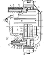
- Figure 1 is a plan view, partly in section, of a disc brake incorporating an anti-rattle spring;
- Figure 2 is an elevation, partly in section, of the brake shown in Figure 1;
- Figure 3 is a perspective view of an anti-rattle spring utilised in Figure 1 and Figure 2; and
- Figure 4 is a perspective view of a wear plate as employed in Figure 1 and Figure 2.
- With reference to Figures 1 and 2 the disc brake of an automobile comprises a cast aluminium
fixed support 11 which in use is bolted to a stationary support e.g. a front wheel stub axle, at one side of a rotary disc 13 (shown in dotted outline) fixed to a wheel hob. The support has a pair of spacedarms 12 that bridge the outer periphery of the disc and whose ends are joined together to form a closed loop. - A pair of
slide pins support 11 and project axially away from the disc 13 (that is axially with respect to the axis of rotation of the disc). Acast aluminium caliper 16, having the shape of a partially closed fist, straddles the outer periphery of thedisc 13, and is axially slidable on thepins caliper 16 comprises twolimbs bridge 19. The onelimb 17 on the same side as thesupport 11 has ahydraulic actuator 21 therein and theother limb 18 lies between thedisc 13 and the closed loop of the support. - The
pin 14 is of stainless steel, and is screwed into thesupport 11 and engages in abore 28 inlimb 17 of thecaliper 16 so that the caliper slides on the pin. Aboot 19 protects the exposed surface of thepin 14. Thepin 15 comprises a stainlesssteel slide bush 24 which is clamped to thesupport 11 by astainless steel bolt 20 which passes through thebush 24 and is screwed into thesupport 11. Anethylenepropylene rubber bush 23 in thelimb 17 of the caliper slides_on__ thisbush 24. Therubber bush 23 has anintegral boot portion 56 which surrounds and protects the outer surface of thebush 24. The hexagon head 25, on thebolt 20, allows thebolt 20 to be unscrewed easily from thesupport 11, and withdrawn to allow the caliper to be pivoted around theother pin 14 for a purpose to be described. - Two opposed
friction pads disc 13 and are located in thesupport 11. Thepads usual friction material 33 mounted onto a mildsteel back plate 34. The pads are arranged between the twolimbs hydraulic actuator 21 acts directly against onepad 32, and indirectly against theother pad 31 through thebridge 19 and theother limb 18. On the application of hydraulic pressure in theactuator 21 the actuator thrusts thepad 32 against one side of the disc and the reaction causes thecaliper 16 to slide on thepins pad 31 to the other side of the disc. The torque load caused by the frictional engagement of thepads disc 13 is reacted on thesupport 11. - The
pads flat surfaces arms 12 of the support. - The
surfaces arms 12 are protected by stainlesssteel wear plates 41 which prevent theback plates 34 of the pads from rubbing against thesofter alumilnum arms 12 and also prevent electro chemical corrosion caused by chemical reaction between the aluminium and mild steel. Each of the wear plates 41 (see Figure 4) comprises a pair ofarms 42 linked by abridge portion 43. Thearms 42 lie one on each side of thedisc 13 and are each dog-leg shaped to follow the contours of thearms 12 and theflat surfaces lug 48 thereon at the corner of the leg between the twosurfaces lugs 48 each project into ahole 44 in an arm to assist location of the respective wear plate. Thebridge portion 43 hastabs 45 at each end that also help to locate the wear plate on the respective arm. Thewear plates 41 form part of thefixed support 11. - The
pads wear plate 41 on the support by a pair of anti-rattle (otherwise known as 'hold down')springs 50. (see Figure 3). Each anti-rattle spring is'T' shaped and thestem 53 of the'T' acts as a leaf spring. One end portion of the spring incorporating thecross piece 51 of the'T' bears in a generally radially inward direction against the twopads stem 53 is bent back to form a 'U'shaped loop 52 that clips over the radially outer side of thearm 12 and so locates the spring on thearm 12. Eachsupport arm 12 has adepression 54 into which aprojection 55 in theloop 52 engages, to hold theclip 50 in the position shown. When fitted in position on the brake caliper theleaf spring 53 passes on the radially inner siides of the arm so that an intermediate portion of the spring bears in a generally radially outward direction against the arm when it reacts on thepads leaf spring 52 passes through the spaced arms of thewear plate 41. The spring acts on the pad in a radially inward direction but may also have a circumferential component of force. - In order to replace
worn pads bolt 25 is removed so that thecaliper 16 becomes freely pivotal onpin 14. The caliper is then pivoted to the position shown in dotted outline, giving ready access to the pads. Withdrawal of theanti-rattle springs 50, which is effected simply by pulling on the ends of the springs in a direction away from the caliper, then enables the old pads to be lifted out and replaced by new ones. The anti-rattle springadjacent pin 14 should preferably be withdrawn before the caliper is pivotted to the dotted position because otherwise the caliper could interfere with access to the spring. The anti-rattle spring nearest topin 15 may be withdrawn either before or after pivotting the caliper away from the support. - When fitting new pads, the piston of
hydraulic actuator 21 should be retracted and the caliper slid alongpin 14 to accommodate the increased thickness of the new pads. - Depending on the orientation of the brake, the new pads may tend to fall out from their correct location until constrained by the anti-rattle springs or the repositioned caliper. For this reason it may be particularly desirable to replace the anti-rattle spring
adjacent pin 20 before re-positioning the caliper. Depending on the installation, it may also be possible to replace the anti-rattle springadjacent pin 14 before re-positioning the caliper. Alternatively, if it is desired to remove and refit the anti-rattle springs without removingpin 20 and pivoting the caliper away from the support this withdrawal and refitting can be effected easily. For example, withdrawal of the springs might be desirable to facilitate close inspection of the pads. - These advantages are brought about by the simple mounting of the anti-rattle springs on the
support arms 12 which extend across the periphery of the disc. - Anti-rattle springs similar to the
springs 50 may be employed in a variety of types of disc brake which have arms corresponding toarms 12 which bridge the outer periphery of the disc, that is not only brakes in which the caliper slides on pins. While it is normally preferable to provide two such anti-rattle springs, one on eacharm 12, a single anti-rattle spring on one arm may be sufficient in some cases. Whilst a pair of common anti-rattle springs acting on both pads is preferred, individual anti-rattle springs arranged side by side and acting one on each pad may be employed instead.
Claims (5)
Applications Claiming Priority (2)
| Application Number | Priority Date | Filing Date | Title |
|---|---|---|---|
| GB8211032 | 1982-04-15 | ||
| GB8211032 | 1982-04-15 |
Publications (2)
| Publication Number | Publication Date |
|---|---|
| EP0094736A1 EP0094736A1 (en) | 1983-11-23 |
| EP0094736B1 true EP0094736B1 (en) | 1986-07-30 |
Family
ID=10529728
Family Applications (1)
| Application Number | Title | Priority Date | Filing Date |
|---|---|---|---|
| EP19830301559 Expired EP0094736B1 (en) | 1982-04-15 | 1983-03-17 | Disc brakes |
Country Status (4)
| Country | Link |
|---|---|
| EP (1) | EP0094736B1 (en) |
| JP (1) | JPS58167328U (en) |
| DE (1) | DE3364842D1 (en) |
| GB (1) | GB2118649B (en) |
Families Citing this family (7)
| Publication number | Priority date | Publication date | Assignee | Title |
|---|---|---|---|---|
| JPH0218353Y2 (en) * | 1985-01-19 | 1990-05-23 | ||
| US4823920A (en) * | 1988-05-02 | 1989-04-25 | Kelsey-Hayes Company | Sliding caliper disc brake and brake shoe assembly therefor |
| US5172792A (en) * | 1991-06-25 | 1992-12-22 | Allied-Signal, Inc. | Modular disc brake |
| DE4126339C2 (en) * | 1991-08-09 | 2002-04-04 | Continental Teves Ag & Co Ohg | Part floating disc brake for high-performance vehicles |
| AU2002320779A1 (en) † | 2002-07-15 | 2004-02-02 | Freni Brembo S.P.A. | Disc brake pad |
| CN111279079B (en) * | 2018-01-31 | 2022-02-11 | 株式会社岛津制作所 | Liquid feeding device of liquid chromatograph |
| DE112020004058T5 (en) * | 2019-08-28 | 2022-08-18 | Hitachi Astemo, Ltd. | disc brake |
Family Cites Families (8)
| Publication number | Priority date | Publication date | Assignee | Title |
|---|---|---|---|---|
| GB934172A (en) * | 1962-07-12 | 1963-08-14 | Girling Ltd | Improvements relating to disc brakes |
| DE1525390B2 (en) * | 1964-02-14 | 1971-11-25 | Alfred Teves Gmbh, 6000 Frankfurt | COMPRESSION SPRING MADE OF SPRING WIRE FOR RESETTING AND HOLDING DOWN THE BRAKE SHOES OF A PARTIAL DISC BRAKE |
| DE1625828C3 (en) * | 1967-09-29 | 1980-04-10 | Alfred Teves Gmbh, 6000 Frankfurt | Floating caliper part-lined disc brake |
| US3625316A (en) * | 1969-02-21 | 1971-12-07 | Aisin Seiki | Antirattling device of disc brake |
| US3612226A (en) * | 1969-10-08 | 1971-10-12 | Bendix Corp | Caliper brake housing support and shoe antirattle spring |
| JPS5386969A (en) * | 1977-01-08 | 1978-07-31 | Aisin Seiki Co Ltd | Disccbrake used pad keep spring |
| JPS6048654B2 (en) * | 1977-08-24 | 1985-10-29 | トヨタ自動車株式会社 | disc brake |
| DE2812718A1 (en) * | 1978-03-23 | 1979-10-04 | Volkswagenwerk Ag | FLOATING CALIPER TYPE DISC BRAKE |
-
1983
- 1983-03-17 DE DE8383301559T patent/DE3364842D1/en not_active Expired
- 1983-03-17 GB GB08307421A patent/GB2118649B/en not_active Expired
- 1983-03-17 EP EP19830301559 patent/EP0094736B1/en not_active Expired
- 1983-04-14 JP JP5484683U patent/JPS58167328U/en active Pending
Also Published As
| Publication number | Publication date |
|---|---|
| GB2118649A (en) | 1983-11-02 |
| GB8307421D0 (en) | 1983-04-27 |
| GB2118649B (en) | 1985-09-25 |
| EP0094736A1 (en) | 1983-11-23 |
| DE3364842D1 (en) | 1986-09-04 |
| JPS58167328U (en) | 1983-11-08 |
Similar Documents
| Publication | Publication Date | Title |
|---|---|---|
| EP1391628B1 (en) | Brake pad and brake caliper for disc brakes | |
| EP0851139B1 (en) | Disk brake | |
| US7631733B2 (en) | Brake assembly | |
| US4034858A (en) | Support structure for a disc brake caliper | |
| US5113978A (en) | Spot type disc brake | |
| AU2017266207B2 (en) | Disc brake for a commercial vehicle, brake pad, and brake pad set | |
| US4611693A (en) | Caliper disc brake | |
| US4034857A (en) | Vehicle disc brake | |
| US5860496A (en) | Pin guided push-pull caliper | |
| JPS6014216B2 (en) | Floating caliper/spot type disc brake | |
| US3917032A (en) | Single mount and guide pin for a caliper of a disc brake assembly | |
| US6957724B2 (en) | Vehicle disk brake | |
| US7316301B2 (en) | Brake caliper | |
| EP0094736B1 (en) | Disc brakes | |
| US4191278A (en) | Slidable support structure for a disc brake caliper | |
| US4784242A (en) | Pad for a disc brake and disc brake equipped with such pads | |
| US4771870A (en) | Brake shoe assembly | |
| EP3810952B1 (en) | Spring for friction pads in a disc brake caliper | |
| US4577731A (en) | Floating caliper spot type disc brake | |
| US5158159A (en) | Spot-type disc brake, in particular for automotive vehicles | |
| EP4107405B1 (en) | Brake pad retainer system, brake pad and vehicle | |
| US7216745B2 (en) | Mounting friction elements to disc brakes | |
| EP0089750B1 (en) | Friction pad assembly for disc brakes | |
| JPS63312526A (en) | Spring for disk brake | |
| EP1650459B1 (en) | Device for retaining the friction linings of a brake disc |
Legal Events
| Date | Code | Title | Description |
|---|---|---|---|
| PUAI | Public reference made under article 153(3) epc to a published international application that has entered the european phase |
Free format text: ORIGINAL CODE: 0009012 |
|
| AK | Designated contracting states |
Designated state(s): BE DE FR GB IT SE |
|
| 17P | Request for examination filed |
Effective date: 19840118 |
|
| GRAA | (expected) grant |
Free format text: ORIGINAL CODE: 0009210 |
|
| AK | Designated contracting states |
Kind code of ref document: B1 Designated state(s): DE FR IT |
|
| REF | Corresponds to: |
Ref document number: 3364842 Country of ref document: DE Date of ref document: 19860904 |
|
| ITF | It: translation for a ep patent filed | ||
| ET | Fr: translation filed | ||
| PLBE | No opposition filed within time limit |
Free format text: ORIGINAL CODE: 0009261 |
|
| STAA | Information on the status of an ep patent application or granted ep patent |
Free format text: STATUS: NO OPPOSITION FILED WITHIN TIME LIMIT |
|
| 26N | No opposition filed | ||
| PG25 | Lapsed in a contracting state [announced via postgrant information from national office to epo] |
Ref country code: DE Effective date: 19871201 |
|
| PGFP | Annual fee paid to national office [announced via postgrant information from national office to epo] |
Ref country code: FR Payment date: 19890208 Year of fee payment: 7 |
|
| PG25 | Lapsed in a contracting state [announced via postgrant information from national office to epo] |
Ref country code: FR Effective date: 19901130 |
|
| REG | Reference to a national code |
Ref country code: FR Ref legal event code: ST |