EP0094579A1 - Pilot-operated pressure limitation valve for fluid circuits under pressure - Google Patents
Pilot-operated pressure limitation valve for fluid circuits under pressure Download PDFInfo
- Publication number
- EP0094579A1 EP0094579A1 EP83104521A EP83104521A EP0094579A1 EP 0094579 A1 EP0094579 A1 EP 0094579A1 EP 83104521 A EP83104521 A EP 83104521A EP 83104521 A EP83104521 A EP 83104521A EP 0094579 A1 EP0094579 A1 EP 0094579A1
- Authority
- EP
- European Patent Office
- Prior art keywords
- valve
- pressure
- piston
- line connection
- main piston
- Prior art date
- Legal status (The legal status is an assumption and is not a legal conclusion. Google has not performed a legal analysis and makes no representation as to the accuracy of the status listed.)
- Granted
Links
Images
Classifications
-
- F—MECHANICAL ENGINEERING; LIGHTING; HEATING; WEAPONS; BLASTING
- F16—ENGINEERING ELEMENTS AND UNITS; GENERAL MEASURES FOR PRODUCING AND MAINTAINING EFFECTIVE FUNCTIONING OF MACHINES OR INSTALLATIONS; THERMAL INSULATION IN GENERAL
- F16K—VALVES; TAPS; COCKS; ACTUATING-FLOATS; DEVICES FOR VENTING OR AERATING
- F16K17/00—Safety valves; Equalising valves, e.g. pressure relief valves
- F16K17/02—Safety valves; Equalising valves, e.g. pressure relief valves opening on surplus pressure on one side; closing on insufficient pressure on one side
- F16K17/04—Safety valves; Equalising valves, e.g. pressure relief valves opening on surplus pressure on one side; closing on insufficient pressure on one side spring-loaded
- F16K17/10—Safety valves; Equalising valves, e.g. pressure relief valves opening on surplus pressure on one side; closing on insufficient pressure on one side spring-loaded with auxiliary valve for fluid operation of the main valve
- F16K17/105—Safety valves; Equalising valves, e.g. pressure relief valves opening on surplus pressure on one side; closing on insufficient pressure on one side spring-loaded with auxiliary valve for fluid operation of the main valve using choking or throttling means to control the fluid operation of the main valve
-
- G—PHYSICS
- G05—CONTROLLING; REGULATING
- G05D—SYSTEMS FOR CONTROLLING OR REGULATING NON-ELECTRIC VARIABLES
- G05D16/00—Control of fluid pressure
- G05D16/04—Control of fluid pressure without auxiliary power
- G05D16/10—Control of fluid pressure without auxiliary power the sensing element being a piston or plunger
-
- Y—GENERAL TAGGING OF NEW TECHNOLOGICAL DEVELOPMENTS; GENERAL TAGGING OF CROSS-SECTIONAL TECHNOLOGIES SPANNING OVER SEVERAL SECTIONS OF THE IPC; TECHNICAL SUBJECTS COVERED BY FORMER USPC CROSS-REFERENCE ART COLLECTIONS [XRACs] AND DIGESTS
- Y10—TECHNICAL SUBJECTS COVERED BY FORMER USPC
- Y10T—TECHNICAL SUBJECTS COVERED BY FORMER US CLASSIFICATION
- Y10T137/00—Fluid handling
- Y10T137/7722—Line condition change responsive valves
- Y10T137/7758—Pilot or servo controlled
- Y10T137/7762—Fluid pressure type
- Y10T137/7764—Choked or throttled pressure type
-
- Y—GENERAL TAGGING OF NEW TECHNOLOGICAL DEVELOPMENTS; GENERAL TAGGING OF CROSS-SECTIONAL TECHNOLOGIES SPANNING OVER SEVERAL SECTIONS OF THE IPC; TECHNICAL SUBJECTS COVERED BY FORMER USPC CROSS-REFERENCE ART COLLECTIONS [XRACs] AND DIGESTS
- Y10—TECHNICAL SUBJECTS COVERED BY FORMER USPC
- Y10T—TECHNICAL SUBJECTS COVERED BY FORMER US CLASSIFICATION
- Y10T137/00—Fluid handling
- Y10T137/7722—Line condition change responsive valves
- Y10T137/7758—Pilot or servo controlled
- Y10T137/7762—Fluid pressure type
- Y10T137/7769—Single acting fluid servo
- Y10T137/777—Spring biased
Definitions
- the invention relates to a pilot-operated pressure relief valve for pressurized fluid lines, which is provided with two line connections, of which one line connection forms the inlet side and the other line connection forms the outlet side and optionally both the one and the other line connection form the inlet side or the outlet side and which has a main piston, which is preceded by a pressure relief valve, which is permanently connected to the respective inlet side during operation, the main piston being cup-shaped and pressurized at its bottom by the pressure in the one line connection.
- Pilot operated pressure relief valves are used to a large extent in the distribution of pressurized fluids wherever relatively large amounts of fluid have to be drained off when the set pressure is exceeded. They essentially consist of a main piston and a pilot valve assigned to the main piston, which is a small, direct-acting pressure relief valve. This opens when the set pressure is exceeded, whereby one surface of the main piston is relieved and relieved the fluid pressure of the main piston is moved into the open position.
- pilot-operated pressure relief valves are used in large numbers and work reliably even with appropriate maintenance, the main piston, especially with large dimensions, is relatively heavy, so that a large mass has to be accelerated when opening, which adversely affects the opening time.
- the weight of the main piston can be reduced if a pressure relief valve based on the cartridge design is used.
- the main piston is hollow and cup-shaped, whereby a substantial reduction in the mass of the main piston is achieved.
- the advantage of this design occurs particularly when this valve is used as a single-acting pressure relief valve.
- the inlet side i.e. the pressure side
- this area can be designed so that it is only a little smaller than the total area of the main piston. This means that the valve responds immediately if the pressure on the side of the main spool opposite the base is only slight.
- the smaller mass of the main piston on the one hand and the lower pressure drop required to respond to the main piston mean that the valve responds more quickly than with a solid piston.
- valves must be used in the cartridge design in fluid systems in which the pressure sides change, so that the higher pressure can occur at both line connections of such a valve, since such a valve can only secure one pressure side, a second valve must be provided for the other pressure side. This represents a relatively large effort, which is why solutions were sought to secure the two pressure sides by means of a single valve.
- the cup-shaped main piston has, in addition to its bottom surface, to which the one line connection connects, a second annular surface which is assigned to the second line connection. Since it is a pilot operated valve, the pilot valve must also be controlled in such a way that it is always connected to the line connection in which the higher pressure prevails.
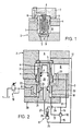
- a single-acting valve in cartridge design is shown. It is designed as a 2-way cartridge valve with the two line connections A, B. It is composed of a sleeve inserted into a bore 1 of a housing 2, a valve piston 4 slidably guided in the sleeve 3 with a valve seat 5 and a closing spring 6.
- the bore 1 is closed by a cover plate 7, in which a pilot line 8 is provided, which connects the interior of the valve piston 4 with a pilot valve or another control device (not shown).
- a narrow bore 9 is provided in the bottom of the valve piston 4, which connects the line connection A to the interior of the valve piston 4 and thus to the pilot valve or the control device.
- the closing spring 6 is a relatively weak spring which practically does not affect the opening process; it closes the valve in the absence of pressure.
- FIG. 1 From Fig. 1 it can be seen that this valve only at can respond to a pressure increase in line connection A.
- the line connection B is not connected to the pilot control (not shown), so that the valve cannot respond depending on the pressure in the line connection B. It is essential that in the valve according to FIG. 1 the surface of the valve piston 4 at the line connection A can be made practically the same size as the diameter of the valve piston 4 in the sleeve 3.
- the valve can always respond when there is a higher pressure in one of the two line connections A, B, a shuttle valve 10 and a pilot-controlled reversing valve 11 are provided.
- the line connection A is connected via a line 12 and the line connection B via a line 13 to the shuttle valve 10 and the reversing valve 11.
- the shuttle valve 10 can be designed, for example, as a check valve with two inlet lines 15, 16 and one outlet line 17.
- the shuttle valve 10 is shown in FIG. 2 for higher pressure in the feed line 15, as a result of which the valve ball is pressed against the feed line 16 and closes it, so that the feed line 15 is connected to the drain line 17, which opens into an annular space 18.
- the pilot line 8 goes from the annular space 18 to a pilot valve 19, which is only shown as a symbol.
- This valve can be designed, for example, as a spring-loaded valve cone that opens rests on a valve seat and blocks line 8. If the pressure exceeds a certain pressure defined by the spring, the valve opens, as a result of which the pressure in the annular space 18 is reduced, since the connecting lines 12, 13 to the line connections A, B are throttled in a suitable manner, for example by a throttle (not shown) are.
- cup-shaped valve piston 4 is connected at its free end to an annular piston 20 which forms two annular surfaces 21, 22.
- the inside diameter of the annular piston 20 can be equal to the outside diameter of the valve piston 4 and the area of the annular surfaces 21, 22 can be the same size.
- the annular surface 22 is connected directly to the line connection B via a line 23.
- the cover plate 7 is closed by a cover 23 which has a projecting pin 24 which forms the inner wall of the annular space 18 for the annular piston 20.
- the pilot-controlled shuttle valve 11 has two inlet lines 25, 26 and an outlet line 27, which is connected to the interior 28 of the valve piston 4.
- the function of the reversing valve is opposite to that of the shuttle valve 10, since the respectively higher pressure in one of the two inlet lines 25, 26 controls the double valve body in such a way that the inlet line with the lower pressure is connected to the outlet line 27.
- This means that the interior 28 is always connected to that of the two line connections A, B in which the lower pressure prevails, which is either equal to the atmospheric pressure or a few bar above this.
- annular space 18 is always connected to that of the two line connections A, B in which the higher pressure prevails.
- the shuttle valve 10 is brought into the position shown in FIG. 2, so that there is a connection between the inlet line 15 and the outlet line 17 and thus with the annular space 18. If the pressure in the line connection A now rises above the pressure set in the pilot control valve 19, this opens and causes the valve piston 4 to open, the pressure fluid flowing after the line connection B. If the greater pressure prevails in the line connection B, the shuttle valve 10 closes the inlet line 15 and connects the inlet line 16 to the outlet line 17 and to the annular space 18. At the same time, the double valve body 29 in the reversing valve 11 is brought into the opposite position as in FIG. ie the inlet line 26 is blocked and the inlet line 25 having the low pressure is connected to the outlet line 27 and to the interior 28 of the valve piston 4.
- the annular piston 18 represents only a small increase in the mass of the valve piston 4, since its overall height need not be significantly greater than the stroke of the valve piston 4. In addition, it is possible without difficulty to make the bottom surface of the valve piston 4 directed against the line connection A the same size as the two ring surfaces 21, 22, as a result of which a high sensitivity is achieved.
- the valve according to FIG. 2 has been described as a double-acting pressure relief valve.
- a valve makes it possible to protect two pressure sides, for example a hydrostatic circuit, with the same value, ie to limit them to the same pressure.
- the flow takes place either from line connection A to line connection B or vice versa.
- the pilot valve 19 on the valve described is replaced by a manually or automatically switching bypass valve, the valve can be used as an idle valve, which connects the two line connections A, B to one another almost without pressure.
Abstract
Description
Die Erfindung betrifft ein vorgesteuertes Druckbegrenzungsventil für unter Druck stehende Fluidleitungen, das mit zwei Leitungsanschlüssen versehen ist, von denen der eine Leitungsanschluss die Zulaufseite und der andere Leitungsanschluss die Ablaufseite bildet und wahlweise sowohl der eine als auch der andere Leitungsanschluss die Zulaufseite oder die Ablaufseite bilden und das einen Hauptkolben aufweist, dem ein Druckbegrenzungsventil vorgeschaltet ist, das im Betrieb dauernd mit der jeweiligen Zulaufseite verbunden ist, wobei der Hauptkolben becherförmig ausgebildet und an seinem Boden vom Druck in dem einen Leitungsanschluss beaufschlagt ist.The invention relates to a pilot-operated pressure relief valve for pressurized fluid lines, which is provided with two line connections, of which one line connection forms the inlet side and the other line connection forms the outlet side and optionally both the one and the other line connection form the inlet side or the outlet side and which has a main piston, which is preceded by a pressure relief valve, which is permanently connected to the respective inlet side during operation, the main piston being cup-shaped and pressurized at its bottom by the pressure in the one line connection.
Vorgesteuerte Druckbegrenzungsventile werden in grossem Umfang bei der Verteilung von unter Druck stehenden Fluiden überall dort verwendet, wo bei Ueberschreiten des eingestellten Druckes rasch verhältnismässig grosse Fluidmengen abgeleitet werden müssen. Sie bestehen im wesentlichen aus einem Hauptkolben und einem dem Hauptkolben zugeordneten Vorsteuerventil, das ein kleines direktwirkendes Druckbegrenzungsventil ist. Dieses öffnet sich bei Ueberschreiten des eingestellten Druckes, wodurch die eine Fläche des Hauptkolbens entlastet und durch den Fluiddruck der Hauptkolben in die Oeffnungsstellung bewegt wird.Pilot operated pressure relief valves are used to a large extent in the distribution of pressurized fluids wherever relatively large amounts of fluid have to be drained off when the set pressure is exceeded. They essentially consist of a main piston and a pilot valve assigned to the main piston, which is a small, direct-acting pressure relief valve. This opens when the set pressure is exceeded, whereby one surface of the main piston is relieved and relieved the fluid pressure of the main piston is moved into the open position.
Obwohl solche vorgesteuerten Druckbegrenzungsventile in grosser Zahl eingesetzt werden und auch bei entsprechender Wartung zuverlässig arbeiten, ist der Hauptkolben, insbesondere bei grossen Dimensionen, verhältnismässig schwer, so dass eine grosse Masse beim Oeffnen beschleunigt werden muss, was die Oeffnungszeit ungünstig beeinflusst.Although such pilot-operated pressure relief valves are used in large numbers and work reliably even with appropriate maintenance, the main piston, especially with large dimensions, is relatively heavy, so that a large mass has to be accelerated when opening, which adversely affects the opening time.
Das Gewicht des Hauptkolbens lässt sich vermindern, wenn ein Druckbegrenzungsventil nach der Cartridge-Bauweise verwendet wird. Bei einem solchen Ventil ist der Hauptkolben hohl und becherförmig ausgebildet, wodurch eine wesentliche Verringerung der Masse des Hauptkolbens erreicht wird. Der Vorteil dieser Bauweise tritt vor allem dann auf, wenn dieses Ventil als einfachwirkendes Druckbegrenzungsventil eingesetzt wird. In diesem Fall ist die Zulaufseite, d.h. die Druckseite,durch den Boden des becherförmigen Hauptkolbens abgeschlossen. Beim einfachwirkenden Druckbegrenzungsventil kann diese Fläche so ausgebildet werden, dass sie nur um ein geringes kleiner ist als die Gesamtfläche des Hauptkolbens. Dies bedeutet, dass bei einer nur geringen Druckerniedrigung auf der dem Boden entgegengesetzten Seite des Hauptkolbens das Ventil sofort anspricht. Die kleinere Masse des Hauptkolbens einerseits und das geringere, zum Ansprechen des Hauptkolbens erforderliche Druckgefälle bewirkt, dass das Ansprechen des Ventils schneller erfolgt als bei einem massiven Kolben.The weight of the main piston can be reduced if a pressure relief valve based on the cartridge design is used. In such a valve, the main piston is hollow and cup-shaped, whereby a substantial reduction in the mass of the main piston is achieved. The advantage of this design occurs particularly when this valve is used as a single-acting pressure relief valve. In this case, the inlet side, i.e. the pressure side, completed by the bottom of the cup-shaped main piston. With the single-acting pressure relief valve, this area can be designed so that it is only a little smaller than the total area of the main piston. This means that the valve responds immediately if the pressure on the side of the main spool opposite the base is only slight. The smaller mass of the main piston on the one hand and the lower pressure drop required to respond to the main piston mean that the valve responds more quickly than with a solid piston.
Müssen solche Ventile in der Cartridge-Bauweise in Fluidsystemen eingesetzt werden, in denen die Druckseiten wechseln, so dass an beiden Leitungsanschlüssen eines solchen Ventils der höhere Druck auftreten kann, muss, da ein solches Ventil nur eine Druckseite absichern kann, ein zweites Ventil für die andere Druckseite vorgesehen werden. Dies stellt einen verhältnismässig grossen Aufwand dar, weshalb Lösungen gesucht wurden, die Absicherung der beiden Druckseiten durch ein einziges Ventil zu erreichen. Bei einer solchen bekannten Ausführungsform (CH-PS 364 671) weist der becherförmige Hauptkolben ausser seiner Bodenfläche, an die der eine Leitungsanschluss anschliesst, eine zweite ringförmige Fläche auf, die dem zweiten Leitungsanschluss zugeordnet ist. Da es sich um ein vorgesteuertes Ventil handelt, muss auch das Vorsteuerventil gesteuert werden, derart, dass es immer mit dem Leitungsanschluss in Verbindung steht, in dem der höhere Druck herrscht. Dies wird bei dem bekannten Ventil durch zwei im Hauptkolben angeordneten Rückschlagventile erreicht, von denenje eines mit einem der beiden Leitungsanschlüsse verbunden ist. Dadurch wird immer dasjenige Rückschlagventil, das am höheren Druck liegt, geöffnet und das andere geschlossen. Mit diesem Ventil wird zwar die vorstehend beschriebene Aufgabe, mit einem einzigen Ventil zwei Druckseiten abzusichern, erreicht, jedoch tritt nun der Nachteil auf, dass sowohl die Bodenfläche als auch die Ringfläche des Hauptkolbens kleiner ist als die Gesamtfläche des Kolbens. Werden beispielsweise die beiden Teilflächen gleichgross ausgelegt, bedeutet dies, dass die Gesamtfläche des Kolbens das Doppelte beträgt. Da jedoch das Ansprechen des Hauptkolbens immer nur durch den Druck auf eine der Teilflächen erfolgt, muss ein verhältnismässig grosses Druckgefälle vorliegen, bevor der Hauptkolben anspricht. Da zudem derDurchmesser des Hauptkolbens entsprechend den beiden Teilflächen grösser ist als für das einfachwirkende Ventil, wird die Masse des Kolbens spürbar vergrössert, wodurch eine weitere Verlangsamung des Oeffnungsvorgangs eintritt.Such valves must be used in the cartridge design in fluid systems in which the pressure sides change, so that the higher pressure can occur at both line connections of such a valve, since such a valve can only secure one pressure side, a second valve must be provided for the other pressure side. This represents a relatively large effort, which is why solutions were sought to secure the two pressure sides by means of a single valve. In such a known embodiment (CH-PS 364 671), the cup-shaped main piston has, in addition to its bottom surface, to which the one line connection connects, a second annular surface which is assigned to the second line connection. Since it is a pilot operated valve, the pilot valve must also be controlled in such a way that it is always connected to the line connection in which the higher pressure prevails. In the known valve, this is achieved by two check valves arranged in the main piston, one of which is connected to one of the two line connections. As a result, the one-way valve that is at the higher pressure is always opened and the other is closed. Although this valve achieves the task described above of securing two pressure sides with a single valve, the disadvantage now arises that both the bottom surface and the annular surface of the main piston are smaller than the total surface of the piston. If, for example, the two partial areas are designed to be the same size, this means that the total area of the piston is double. However, since the main piston always responds only through the pressure on one of the partial surfaces, there must be a relatively large pressure drop before the main piston responds. Since the diameter of the main piston also corresponds to the two partial surfaces is greater than for the single-acting valve, the mass of the piston is increased appreciably, thus further slowing down of the O effnungsvorgangs occurs.
Hier setzt die Erfindung ein, der die Aufgabe zugrundeliegt, ein Druckbegrenzungsventil der eingangs beschriebenen Art so auszugestalten, dass das rasche Ansprechen wie beim einfachwirkenden Ventil erhalten bleibt, obwohl das Ventil als doppeltwirkendes Ventil eingesetzt werden kann.This is where the invention comes in, which is based on the object of designing a pressure relief valve of the type described at the outset in such a way that the rapid response remains as in the case of the single-acting valve, although the valve can be used as a double-acting valve.
Diese Aufgabe wird gemäss der Erfindung durch die kennzeichnenden Merkmale des Anspruchs 1 gelöst. Dadurch, dass der Hauptkolben selbst unverändert bleibt und nur durch einen Ringkolben ergänzt wird, der zudem sehr kurz gehalten werden kann, da die Führung vom Hauptkolben übernommen wird, wird erreicht, dass unabhängig davon, an welchem der beiden Leitungsanschlüsse der höhere Druck herrscht, die jeweilige Druckfläche des Leitungsanschlusses und die dem Vorsteuerventil zugewandte Fläche des Hauptkolbens annähernd gleichgross sein können. Durch die mindestens annähernde Gleichheit der massgebenden Flächen am Hauptkolben und durch die nur geringfügige Vergrösserung der Masse des Hauptkolbens bleibt die Ansprechgeschwindigkeit eines solchen doppeltwirkenden Druckbegrenzungsventils mit derjenigen eines einfachwirkenden Ventils in Cartridge-Bauweise vergleichbar.This object is achieved according to the invention by the characterizing features of claim 1. The fact that the main piston itself remains unchanged and is only supplemented by an annular piston, which can also be kept very short, since the main piston takes over the guidance, ensures that regardless of which of the two line connections the higher pressure prevails The respective pressure surface of the line connection and the surface of the main piston facing the pilot valve can be approximately the same size. Due to the at least approximately equal equality of the decisive areas on the main piston and the only slight increase in the mass of the main piston, the response speed of such a double-acting pressure relief valve remains comparable to that of a single-acting valve in a cartridge design.
Die Erfindung ist in der Zeichnung in einem Ausführungsbeispiel dargestellt und nachfolgend beschrieben. Es zeigen:
- Fig. 1 einen Vertikalschnitt eines schematisch dargestellten Ventils in Cartridge-Bauweise und
- Fig. 2 einen Vertikalschnitt eines doppeltwirkenden, vorgesteuerten Druckbegrenzungsventils mit in Schaltsymbolen dargestellten Vorsteuerventil, Wechselventil und Umsteuerventil.
- Fig. 1 is a vertical section of a schematically shown valve in cartridge design and
- Fig. 2 is a vertical section of a double-acting, pilot-controlled pressure relief valve with pilot valve, shuttle valve and reversing valve shown in circuit symbols.
In Fig. 1 ist ein einfachwirkendes Ventil in Cartridge-Bauweise dargestellt. Es ist als 2-Weg-Einbauventil mit den beiden Leitungsanschlüssen A, B ausgebildet. Es setzt sich aus einer, in eine Bohrung 1 eines Gehäuses 2 eingesetzten Hülse, einem in der Hülse 3 verschiebbar geführten Ventilkolben 4 mit einem Ventilsitz 5 und einer Schliessfeder 6 zusammen. Die Bohrung 1 ist durch eine Deckplatte 7 abgeschlossen, in der eine Vorsteuerleitung 8 vorgesehen ist, die den Innenraum des Ventilkolbens 4 mit einem Vorsteuerventil oder einer andern Steuereinrichtung (nicht dargestellt) verbindet. Im Boden des Ventilkolbens 4 ist eine enge Bohrung 9 vorgesehen, die den Leitungsanschluss A mit dem Innenraum des Ventilkolbens 4 und damit mit dem Vorsteuerventil bzw. der Steuereinrichtung verbindet. Steigt der Druck im Leitungsanschluss Aüber den am Vorsteuerventil bzw. an der Steuereinrichtung eingestellten Druck öffnet es, so dass der Druck im Innern des Ventilkolbens 4 sinkt und der Kolben 4 öffnet. Die Schliessfeder 6 ist eine verhältnismässig schwache Feder, die den Oeffnungsvorgang praktisch nicht beeinflusst; sie schliesst das Ventil bei fehlendem Druck.In Fig. 1, a single-acting valve in cartridge design is shown. It is designed as a 2-way cartridge valve with the two line connections A, B. It is composed of a sleeve inserted into a bore 1 of a
Aus Fig. 1 ist ersichtlich, dass dieses Ventil nur bei einer Drucksteigerung im Leitungsanschluss A ansprechen kann. Der Leitungsanschluss B ist nicht mit der (nicht dargestellten) Vorsteuerung verbunden, so dass kein Ansprechen des Ventils in Abhängigkeit vom Druck im Leitungsanschluss B erfolgen kann. Wesentlich ist, dass beim Ventil nach Fig. 1 die Fläche des Ventilkolbens 4 am Leitungsanschluss A praktisch gleichgross ausgeführt werden kann wie der Durchmesser des Ventilskolbens 4 in der Hülse 3.From Fig. 1 it can be seen that this valve only at can respond to a pressure increase in line connection A. The line connection B is not connected to the pilot control (not shown), so that the valve cannot respond depending on the pressure in the line connection B. It is essential that in the valve according to FIG. 1 the surface of the valve piston 4 at the line connection A can be made practically the same size as the diameter of the valve piston 4 in the
Im Druckbegrenzungsventil nach Fig. 2, das als doppeltwirkendes Ventil ausgebildet ist, bedeuten gleiche Bezugszeichen, gleiche Teile. Es liegt eine weitgehende Uebereinstimmung mit dem Ventil nach Fig. 1 vor.2, which is designed as a double-acting valve, mean the same reference numerals, same parts. There is extensive agreement with the valve according to FIG. 1.
Damit das Ventil immer dann ansprechen kann, wenn in einem der beiden Leitungsanschlüsse A, B ein höherer Druck herrscht, ist ein Wechselventil 10 und ein vorgesteuertes Umsteuerventil 11 vorgesehen. Der Leitungsanschluss A ist über eine Leitung 12 und der Leitungsanschluss B über eine Leitung 13 mit dem Wechselventil 10 und dem Umsteuerventil 11 verbunden. Das Wechselventil lO kann beispielweise als Rückschlagventil mit zwei Zulaufleitungen 15, 16 und einer Ablaufleitung 17 ausgebildet sein. Das Wechselventil lO ist in Fig. 2 für höherem Druck in der Zulaufleitung 15 dargestellt, wodurch die Ventilkugel gegen die Zulaufleitung 16 gedrückt wird und diese schliesst, so dass die Zulaufleitung 15 mit der Ablaufleitung 17 verbunden ist, die in einen Ringraum 18 mündet. Aus dem Ringraum 18 geht die Vorsteuerleitung 8 zu einem Vorsteuerventil 19, das lediglich als Symbol dargestellt ist. Dieses Ventil kann beispielsweise als federbelasteter Ventilkegel ausgebildet sein, der auf einem Ventilsitz aufliegt und die Leitung 8 sperrt. Ueberschreitet der Druck einen bestimmten, durch die Feder definierten Druck, öffnet das Ventil, wodurch der Druck im Ringraum 18 abgesenkt wird, da die Verbindungsleitungen 12, 13 zu den Leitungsanschlüssen A, B in geeigneter Weise, z.B. durch eine Drossel (nicht dargestellt) gedrosselt sind.So that the valve can always respond when there is a higher pressure in one of the two line connections A, B, a
Wesentlich ist, dass der becherförmig ausgebildete Ventilkolben 4 an seinem freien Ende mit einem Ringkolben 20 verbunden ist, der zwei Ringflächen 21, 22 bildet. Es kann der Innendurchmesser des Ringkolbens 20 gleich dem Aussendurchmessers des Ventilkolbens 4 und die Fläche der Ringflächen 21, 22 gleichgross sein. Die Ringfläche 22 ist über eine Leitung 23 mit dem Leitungsanschluss B direkt verbunden.It is essential that the cup-shaped valve piston 4 is connected at its free end to an
Die Deckplatte 7 ist durch einen Deckel 23 abgeschlossen, der einen vorspringenden Zapfen 24 aufweist, der die Innenwandung des Ringraums 18 für den Ringkolben 20 bildet.The cover plate 7 is closed by a
Das vorgesteuerte Wechselventil 11 weist zwei Zulaufleitungen 25, 26 und eine Ablaufleitung 27 auf, die mit dem Innenraum 28 des Ventilkolbens 4 verbunden ist. Die Funktion des Umsteuerventils ist entgegengesetzt derjenigen des Wechselventils 10, da der jeweilig höhere Druck in einer der beiden Zulaufleitungen 25, 26 den Doppelventilkörper derart steuert, dass die Zulaufleitung mit dem kleineren Druck mit der Ablaufleitung 27 verbunden wird. Dies bedeutet, dass der Innenraum 28 immer mit demjenigen der beiden Leitungsanschlüsse A, B verbunden ist, in dem der kleinere Druck herrscht, der entweder gleich dem Atmosphärendruck ist oder einige Bar über diesem liegt. Andererseits ist derThe pilot-controlled
Ringraum 18 wegen der Funktion des Wechselventils lO immer mit demjenigen der beiden Leitungsanschlüsse A, B verbunden, in dem der höhere Druck herrscht.Because of the function of the
Weist der Leitungsanschluss A den höheren Druck auf, wird das Wechselventil 10 in die in Fig. 2 dargestellte Lage gebracht, so dass eine Verbindung zwischen der Zulaufleitung 15 und der Ablaufleitung 17 und damit mit dem Ringraum 18 besteht. Steigt nun im Leitungsanschluss A der Druck über den im Vorsteuerventil 19 eingestellten Druck, öffnet sich dieses und bewirkt das Oeffnen des Ventilkolbens 4, wobei das Druckfluid nach dem Leitungsanschluss B fliesst. Herrscht im Leitungsanschluss B der grössere Druck, schliesst das Wechselventil 10 die Zulaufleitung 15 und verbindet die Zulaufleitung 16 mit der Ablaufleitung 17 und.mit dem Ringraum 18. Gleichzeitig wird der Doppelventilkörper 29 im Umsteuerventil 11 in die entgegengesetzte Lage wie in Fig.2 gebracht, d.h. die Zulaufleitung 26 wird gesperrt und die den niederen Druck aufweisende Zulaufleitung 25 mit der Ablaufleitung 27 und mit dem Innenraum 28 des Ventilkolbens 4 verbunden.If the line connection A has the higher pressure, the
Der Ringkolben 18 stellt nur eine geringe Vergrösserung der Masse des Ventilkolbens 4 dar, da seine Bauhöhe nicht wesentlich grösser als der Hub des Ventilkolbens 4 zu sein braucht. Zudem ist es ohne Schwierigkeit möglich, die Bodenfläche des gegen den Leitungsanschluss A gerichteten Ventilkolbens 4 gleichgross auszuführen wie die beiden Ringflächen 21, 22, wodurch eine hohe Ansprechempfindlichkeit erreicht wird.The
Das Ventil nach Fig. 2 wurde in der Ausführung als doppeltwirkendes Druckbegrenzungsventil beschrieben. Mit einem solchen Ventil ist es möglich, zwei Druckseiten, z.B. eines hydrostatischen Kreislaufes, gleichwertig abzusichern, d.h. auf denselben Druck zu begrenzen. Hierbei erfolgt der Durchfluss entweder vom Leitungsanschluss A nach dem Leitungsanschluss B oder umgekehrt. Wird an dem beschriebenen Ventil das Vorsteuerventil 19 durch ein manuell oder selbsttätig schaltendes Bypassventil ersetzt, kann das Ventil als Leerlaufventil verwendet werden, das die beiden Leitungsanschlüsse A, B annähernd drucklos miteinander verbindet.The valve according to FIG. 2 has been described as a double-acting pressure relief valve. With a Such a valve makes it possible to protect two pressure sides, for example a hydrostatic circuit, with the same value, ie to limit them to the same pressure. Here, the flow takes place either from line connection A to line connection B or vice versa. If the
Claims (7)
Priority Applications (1)
| Application Number | Priority Date | Filing Date | Title |
|---|---|---|---|
| AT83104521T ATE27051T1 (en) | 1982-05-19 | 1983-05-07 | PILOT ACTUATED PRESSURE RELIEF VALVE FOR PRESSURIZED FLUID LINES. |
Applications Claiming Priority (2)
| Application Number | Priority Date | Filing Date | Title |
|---|---|---|---|
| CH3131/82A CH658895A5 (en) | 1982-05-19 | 1982-05-19 | PRESSURE LIMIT VALVE FOR PRESSURED FLUID PIPES. |
| CH3131/82 | 1982-05-19 |
Publications (2)
| Publication Number | Publication Date |
|---|---|
| EP0094579A1 true EP0094579A1 (en) | 1983-11-23 |
| EP0094579B1 EP0094579B1 (en) | 1987-05-06 |
Family
ID=4249284
Family Applications (1)
| Application Number | Title | Priority Date | Filing Date |
|---|---|---|---|
| EP83104521A Expired EP0094579B1 (en) | 1982-05-19 | 1983-05-07 | Pilot-operated pressure limitation valve for fluid circuits under pressure |
Country Status (6)
| Country | Link |
|---|---|
| US (1) | US4531540A (en) |
| EP (1) | EP0094579B1 (en) |
| AT (1) | ATE27051T1 (en) |
| CH (1) | CH658895A5 (en) |
| DE (1) | DE3371401D1 (en) |
| ZA (1) | ZA832349B (en) |
Cited By (1)
| Publication number | Priority date | Publication date | Assignee | Title |
|---|---|---|---|---|
| FR2686679A1 (en) * | 1992-01-28 | 1993-07-30 | Reglage Thermique Ste Alsacien | Safety device protecting against excess pressures of a fluid confined in an enclosure |
Families Citing this family (5)
| Publication number | Priority date | Publication date | Assignee | Title |
|---|---|---|---|---|
| DE8817026U1 (en) * | 1988-01-13 | 1992-03-05 | Barth, Hans, 7801 Schallstadt, De | |
| LU88384A1 (en) * | 1993-07-16 | 1995-02-01 | Hydrolux Sarl | 2-way cartridge valve as a seat valve |
| US7490625B1 (en) | 2001-04-23 | 2009-02-17 | John Leslie Johnson | Pilot valve manifold |
| CA2581123C (en) * | 2004-09-20 | 2015-07-07 | Magna Powertrain Inc. | Pump with selectable outlet pressure |
| CN101943188B (en) * | 2010-04-29 | 2013-08-21 | 上海人豪液压技术有限公司 | Compact two-way cartridge valve adopting combined type flange control cover plate |
Citations (2)
| Publication number | Priority date | Publication date | Assignee | Title |
|---|---|---|---|---|
| DE1775178B2 (en) * | 1968-07-13 | 1975-04-10 | G.L. Rexroth Gmbh, 8770 Lohr | |
| DE2527249A1 (en) * | 1974-06-21 | 1976-01-08 | Hoerbiger Fluidtechnik Kg | PRESSURE REGULATOR FOR STREAMING MEDIA |
Family Cites Families (5)
| Publication number | Priority date | Publication date | Assignee | Title |
|---|---|---|---|---|
| US2612019A (en) * | 1949-01-03 | 1952-09-30 | Havilland Engine Co Ltd | Propellent injection system with safety valve to cut off fluid pressure supply |
| US3060951A (en) * | 1956-12-26 | 1962-10-30 | Alsacienne Constr Meca | Hydraulic regulating system |
| CH364671A (en) * | 1958-12-02 | 1962-09-30 | Von Roll Ag | Pilot operated safety valve |
| US3238966A (en) * | 1963-06-28 | 1966-03-08 | Charles N Howard | Fluid operated control valve and gas control system |
| US4000754A (en) * | 1974-06-11 | 1977-01-04 | Maxton Manufacturing Company | Automatic control valve for a fluid system |
-
1982
- 1982-05-19 CH CH3131/82A patent/CH658895A5/en not_active IP Right Cessation
-
1983
- 1983-03-31 ZA ZA832349A patent/ZA832349B/en unknown
- 1983-05-07 DE DE8383104521T patent/DE3371401D1/en not_active Expired
- 1983-05-07 AT AT83104521T patent/ATE27051T1/en not_active IP Right Cessation
- 1983-05-07 EP EP83104521A patent/EP0094579B1/en not_active Expired
- 1983-05-13 US US06/494,319 patent/US4531540A/en not_active Expired - Fee Related
Patent Citations (2)
| Publication number | Priority date | Publication date | Assignee | Title |
|---|---|---|---|---|
| DE1775178B2 (en) * | 1968-07-13 | 1975-04-10 | G.L. Rexroth Gmbh, 8770 Lohr | |
| DE2527249A1 (en) * | 1974-06-21 | 1976-01-08 | Hoerbiger Fluidtechnik Kg | PRESSURE REGULATOR FOR STREAMING MEDIA |
Cited By (1)
| Publication number | Priority date | Publication date | Assignee | Title |
|---|---|---|---|---|
| FR2686679A1 (en) * | 1992-01-28 | 1993-07-30 | Reglage Thermique Ste Alsacien | Safety device protecting against excess pressures of a fluid confined in an enclosure |
Also Published As
| Publication number | Publication date |
|---|---|
| US4531540A (en) | 1985-07-30 |
| EP0094579B1 (en) | 1987-05-06 |
| ATE27051T1 (en) | 1987-05-15 |
| DE3371401D1 (en) | 1987-06-11 |
| ZA832349B (en) | 1983-12-28 |
| CH658895A5 (en) | 1986-12-15 |
Similar Documents
| Publication | Publication Date | Title |
|---|---|---|
| DE1576088A1 (en) | Quick relief valve for hydraulic power cylinders | |
| DE2126763A1 (en) | Hydraulic control valve | |
| DE2551489A1 (en) | CONTROL VALVE IN HYDRAULIC CIRCUITS | |
| EP0094579B1 (en) | Pilot-operated pressure limitation valve for fluid circuits under pressure | |
| DE1947678A1 (en) | Pressure control valve with multiple scanner members | |
| DE3341643A1 (en) | Pilot-controlled pressure relief and control valve | |
| DE2407177A1 (en) | HIGH PRESSURE RELEASE VALVE | |
| DE3404982C2 (en) | ||
| DE3218527C2 (en) | ||
| DE1006685B (en) | Device for regulating the pressure within narrow limits in a hydraulic system and / or a memory | |
| DE3006530A1 (en) | Hydraulic locking ball valve - has valve controlled suction device reducing pressure in actuation chamber to open valve | |
| DE3243182C2 (en) | ||
| DE1103098B (en) | Multipurpose control valve | |
| DE2932523C2 (en) | Hydraulically releasable seat valve | |
| DE2240012C3 (en) | Control device for hydrostatic power steering or the like. | |
| DE2038813C2 (en) | Pressure operated multiway valve - has spring centred plunger sliding in axially adjustable cylindrical pot | |
| DE2536784C3 (en) | Hydraulic valve device for route control of the working pressure medium for a hydraulic servomotor | |
| DE2307285A1 (en) | VALVE, IN PARTICULAR VENTILATION VALVE | |
| DE1222754B (en) | Pipe rupture valve | |
| DE1101887B (en) | Hydraulic control device | |
| DE2833971A1 (en) | Pipe burst safety unit for hydraulic systems - has back pressure valves in passage between control and cylinder connection | |
| DE936130C (en) | Device for pressure-dependent control of a hydraulic system | |
| DE2034214A1 (en) | Control device for a hydraulic working group | |
| DE2602923C3 (en) | Brake valve | |
| DE3136535C2 (en) |
Legal Events
| Date | Code | Title | Description |
|---|---|---|---|
| PUAI | Public reference made under article 153(3) epc to a published international application that has entered the european phase |
Free format text: ORIGINAL CODE: 0009012 |
|
| AK | Designated contracting states |
Designated state(s): AT DE FR GB |
|
| RAP1 | Party data changed (applicant data changed or rights of an application transferred) |
Owner name: VON ROLL - HYDRAULIK A.G. |
|
| 17P | Request for examination filed |
Effective date: 19840220 |
|
| GRAA | (expected) grant |
Free format text: ORIGINAL CODE: 0009210 |
|
| AK | Designated contracting states |
Kind code of ref document: B1 Designated state(s): AT DE FR GB |
|
| REF | Corresponds to: |
Ref document number: 27051 Country of ref document: AT Date of ref document: 19870515 Kind code of ref document: T |
|
| REF | Corresponds to: |
Ref document number: 3371401 Country of ref document: DE Date of ref document: 19870611 |
|
| ET | Fr: translation filed | ||
| PLBE | No opposition filed within time limit |
Free format text: ORIGINAL CODE: 0009261 |
|
| STAA | Information on the status of an ep patent application or granted ep patent |
Free format text: STATUS: NO OPPOSITION FILED WITHIN TIME LIMIT |
|
| 26N | No opposition filed | ||
| PGFP | Annual fee paid to national office [announced via postgrant information from national office to epo] |
Ref country code: GB Payment date: 20010412 Year of fee payment: 19 |
|
| PGFP | Annual fee paid to national office [announced via postgrant information from national office to epo] |
Ref country code: AT Payment date: 20010427 Year of fee payment: 19 |
|
| PGFP | Annual fee paid to national office [announced via postgrant information from national office to epo] |
Ref country code: FR Payment date: 20010507 Year of fee payment: 19 |
|
| PGFP | Annual fee paid to national office [announced via postgrant information from national office to epo] |
Ref country code: DE Payment date: 20010509 Year of fee payment: 19 |
|
| REG | Reference to a national code |
Ref country code: GB Ref legal event code: IF02 |
|
| PG25 | Lapsed in a contracting state [announced via postgrant information from national office to epo] |
Ref country code: GB Free format text: LAPSE BECAUSE OF NON-PAYMENT OF DUE FEES Effective date: 20020507 Ref country code: AT Free format text: LAPSE BECAUSE OF NON-PAYMENT OF DUE FEES Effective date: 20020507 |
|
| PG25 | Lapsed in a contracting state [announced via postgrant information from national office to epo] |
Ref country code: DE Free format text: LAPSE BECAUSE OF NON-PAYMENT OF DUE FEES Effective date: 20021203 |
|
| GBPC | Gb: european patent ceased through non-payment of renewal fee |
Effective date: 20020507 |
|
| PG25 | Lapsed in a contracting state [announced via postgrant information from national office to epo] |
Ref country code: FR Free format text: LAPSE BECAUSE OF NON-PAYMENT OF DUE FEES Effective date: 20030131 |
|
| REG | Reference to a national code |
Ref country code: FR Ref legal event code: ST |