EP0094532A2 - Toy airplane emitting bubbles of the type of soap bubbles - Google Patents
Toy airplane emitting bubbles of the type of soap bubbles Download PDFInfo
- Publication number
- EP0094532A2 EP0094532A2 EP83104213A EP83104213A EP0094532A2 EP 0094532 A2 EP0094532 A2 EP 0094532A2 EP 83104213 A EP83104213 A EP 83104213A EP 83104213 A EP83104213 A EP 83104213A EP 0094532 A2 EP0094532 A2 EP 0094532A2
- Authority
- EP
- European Patent Office
- Prior art keywords
- pan
- toy airplane
- bubbles
- rings
- airscrew
- Prior art date
- Legal status (The legal status is an assumption and is not a legal conclusion. Google has not performed a legal analysis and makes no representation as to the accuracy of the status listed.)
- Withdrawn
Links
- 239000000344 soap Substances 0.000 title claims description 7
- 239000007788 liquid Substances 0.000 claims abstract description 17
- 230000005540 biological transmission Effects 0.000 claims description 2
- 230000002093 peripheral effect Effects 0.000 claims description 2
- 101100327917 Caenorhabditis elegans chup-1 gene Proteins 0.000 description 8
- 238000007664 blowing Methods 0.000 description 2
- 238000003780 insertion Methods 0.000 description 2
- 230000037431 insertion Effects 0.000 description 2
- 230000033001 locomotion Effects 0.000 description 2
- 239000000463 material Substances 0.000 description 2
- 239000002184 metal Substances 0.000 description 2
- 230000015572 biosynthetic process Effects 0.000 description 1
- 239000003086 colorant Substances 0.000 description 1
- 238000005034 decoration Methods 0.000 description 1
- 239000013013 elastic material Substances 0.000 description 1
- 238000009434 installation Methods 0.000 description 1
- 238000000465 moulding Methods 0.000 description 1
Images
Classifications
-
- A—HUMAN NECESSITIES
- A63—SPORTS; GAMES; AMUSEMENTS
- A63H—TOYS, e.g. TOPS, DOLLS, HOOPS OR BUILDING BLOCKS
- A63H27/00—Toy aircraft; Other flying toys
-
- A—HUMAN NECESSITIES
- A63—SPORTS; GAMES; AMUSEMENTS
- A63H—TOYS, e.g. TOPS, DOLLS, HOOPS OR BUILDING BLOCKS
- A63H33/00—Other toys
- A63H33/28—Soap-bubble toys; Smoke toys
Definitions
- the pan 39 is of parallelepipedal shape at the top, and has at the bottom a deepening and narrowing portion 40 the periphery whereof is defined by an arc of a circle centered on the axis of the hub 31.
- the hub is carried rotatably at the saddles 41 and 42, formed in the front and rear edges, respectively, of the pan 39.
- the operation of the toy airplane may be readily appreciated from the foregoing description.
- the airscrew 25 meets a flow of air and is rotated; owing to its size, the airscrew power is adequate to drive, by suitable reduction through the reduction gear 23, the rings 46 and vanes 47.
- the rings are dipped into the liquid contained in the pan 39 and raised above the latter where they are swept by the air stream, which meets favorably the sloping flattening 6.
- long bubble trains are emitted.
- the bubbles are formed in a substantially continuous fashion and without conventionally blowing directly by the user.
Landscapes
- Toys (AREA)
Abstract
This toy airplane comprises a shaped body (1,2), means (48) adapted to lock the latter to a vehicle such as a bicycle, an airscrew (25) mounted rotatably on the front of the body (1,2). a pan (39) defined rearwardly and transversely to the body (1,2) and intended for containing the bubble forming liquid, arm members (45) carrying at the periphery thereof rings (46) adapted for retaining the bubble forming liquid and carried rotatably at the top of the pan (39) and transversely to the body (1,2), and a kinematic linkage interposed between the airscrew (25) and arm members (45).
Description
- This invention relates to a toy airplane for emitting bubbles of the type of soap bubbles.
- It is known that playing with soap bubbles is still a widespread recreation, for the emission of such bubbles blow rings being usually utilized which, when dipped into a special liquid, are effective to retain said liquid; the user, by blowing from his/her mouth onto the ring, causes one or more bubbles to issue therefrom. Such blow rings, which require direct operation by the user, can only afford, however, limited playing potential to children, to whom they are specially directed, thereby there is a need for association of bubble emitting with new forms of play.
- Thus, the task of this invention is to provide a toy airplane, whereby bubbles of the type of soap bubbles can be emitted in a substantially continuous fashion and without requiring direct operation by the user.
- Within that task it is an object of the invention to provide a toy airplane which is of simple design, easy and safe to use, and of relatively low cost.
- According to one aspect of the invention the above task and object are achieved by a toy airplane for emitting bubbles of the type of soap bubbles, characterized in that it comprises a shaped body, means adapted to secure the latter to a vehicle, an airscrew mounted rotatable on said body, a pan rigid with said body and intended to contain a bubble forming liquid therein, arm members carrying peripheral rings adapted to retain said liquid and being supported rotatably near said pan so as to cause said rings to be alternately dipped in the pan liquid and be raised out of said pan, and transmission means interposed between said airscrew and arm members such that the latter are effective to be rotated by the former.
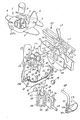
- The invention details will be more clearly understood from the following description of a preferred embodiment of the.toy airplane for emitting bubbles, illustrated by way of example in the accompanying drawing, the one figure whereof is an exploded perspective view, partly cutaway, of the toy airplane.
- With particular reference to the drawing figure, this toy airplane comprises a correspondingly shaped body which includes an upper cup 1 and a lower cup 2.As explained hereinafter, the two cups are secured to each other with their edges mutually engaged and their hollows facing each other so as to enclose a cavity on their interiors. In general, the body 1-2 follows a cylindrical pattern at the front and middle, to then taper rearwardly to define the plane tail. At the edge portion, the upper cup 1 has opposed pairs of foil-
like projections center projections 3 andrear ones 4 define the wings and tailplanes, respectively, of the airplane. The airplane fin is instead defined by the foil-like ridge 5 which lies on a longitudinal plane to the body 1-2 and raises from the rear portion of the cup 1, correspondingly formed with a sloping flat 6. - At the middle, the cup 1 defines the airplane cockpit at a
recess 7, wherein a substantially cylindrical block 8 is partly accommodated; the block has formed at its bottom the peg 8a, which is intended for a pressure fit in some form of a tube 9 extending upwardly from the bottom of the hollow 7; the upper portion of the block 8, with the latter so inserted, is intended to protrude from the cup 1 and represent the face of the airplane pilot. At a position remote from the tube 9, the bottom of the hollow 7 is also affected by some form of a well 10, the function whereof will be explained hereinafter. Abase 11 is secured within the front portion of thecup 2; to this end twohooks 12, which extend upwardly from the bottom of the cup, are adapted to snap engage elastically withrespective serrations 13 defined by the base and to hold the latter abutted against the cup. Thehooks 12 are arranged to face each other on said longitudinal plane of the airplane and are at the edges ofrespective slots 14 of the bottom of thecup 2; it is, in fact, contemplated that the cup 2 (like, after all, the cup 1 and base 11) be molded from a plastic material, and accordingly, theslots 14 allows that, with the same molding operation as the cup, the hooks be formed. As shown, theserrations 13 are formed at the center of the sides which thebase 14 presents transverse to the airplane. At the two other sides of its, the base hasrespective lugs 15, facing downwards. By passing through respectiveshaped slots 16 formed in thecup 2, thelugs 15 locate themselves below the cup, so as to carry rotatablyrespective wheels 17 of the airplane. Thelugs 15 define, in fact, at the bottom thereof,respective pins 18, one of which faces upwards; each pin has its end enlarged and is formed with a throughgoing cutout so as to permit insertion of the wheel with a snap action and hold it in the axial direction. Afurther tail wheel 19 is mounted on asimilar pin 20 defined by alug 21 which thecup 2 has at the bottom from one edge of itsslot 22. - The
base 11 supports at the top a. reduction gear" which is generally indicated at 23 and is, hence, located inside the cavity enclosed between thecups 1 and 2. Theinput shaft 24 of thereduction gear 23 carries rigidly mounted thereon, respectively at the front end and rear one, anairscrew 25 and a pinion gear 26. The two-bladed airscrew 25 is oversize relatively to the body 1-2, with respect to which it is frontally external and rotatable. Theshaft 24 is thin, being particularly formed from metal, and is longitudinal to the body 1-2; that same shaft, in the proximities of the airscrew, is passed through and engages rotatably with some form of a bushing which comprises two corresponding bosses 27a-27b formed at the front by the edge of therespective cups 1 and 2. In the proximities of the pinion gear 26, theshaft 24 is coupled rotatably in some forms of saddles which are defined at the free ends of twoflanges 28a and 28b; theflange 28a extends from the cup 1 down, whereas the flange 28b extends from the front side of thebase 11 up; the two flanges extend on two adjacent planes transversely to the body 1-2 of the airplane. - The bosses 27a-b and
flange 28a-b form, however, shoulders for the hub of theairscrew 25 and pinion gear 26, thereby theshaft 24 is locked in the axial direction. - The output of the
reduction gear 23 is provided by ashaft 29 which has its axis in common with theshaft 24 and is located at the rear of the latter, being also thin and made of metal. At its front end, theshaft 29 has agear wheel 30 rigid therewith, and at its rear end, which extends outside the body 1-2, it has an elongate hub 31 rigid therewith. In the proximities of thewheel 30, theshaft 29 is rotatably coupled to the free ends of twoflanges 32a, 32b; similarly to theflanges 28a and 28b, the flange 32a extends from the cup 1 and theflange 32b extends from the rear side of thebase 11 adjacently the flange 32a. In addition to the pinion gear 26 andwheel 30, thereduction gear 23 comprises awheel 33, which meshes with the pinion gear 26 and is made rigid with asmall shaft 34 extending parallel to theshafts shaft 34 is supported rotatably by a pair offlanges 35 - which extend from the
base 11 upwards, and carries a pinion gear, not shown in the drawing, rigid therewith and meshing with thewheel 30. In the proximities of the hub 31, theshaft 29 is passed through and engages pivotally with some form of a bushing, which comprises two corresponding bosses formed rearwardly by the edges of thecups 1 and 2; of such bosses, the drawing figure only shows that relative to thecup 2, which is indicated at 36. - The
boss 36 is terminated rearwardly of the body 1-2 by defining, in a transverse plane to the body, a pair of upturnings 37, opposite each other and facing either sides of said body. Intended for insertion and engagement above the upturning pair, are a pair of small boxes - 38, which open downwards and toward each other. Theboxes 38 are defined at the front and center of the upper region of the front wall of asmall pan 39, which is attached permanently to the rear of the body 1-2 through said boxes. The pan is intended to contain the bubble forming liquid, is flattened and extends across the body 1-2, having its edge practically contained in the same plane as the edge of thecup 2. Thepan 39 is of parallelepipedal shape at the top, and has at the bottom a deepening and narrowingportion 40 the periphery whereof is defined by an arc of a circle centered on the axis of the hub 31. The hub is carried rotatably at thesaddles pan 39. Intended for press-fit engagement with said edge is aframe 43 which, excepting for the areas corresponding to the hub 31 andsaddles lip member 44; after the frame has been mounted on the pan, said lip locates itself inside the latter and facing downwards, thereby between the lip and sidewalls of the pan upper portion, there is defined a substantially annular space open downwards and being adapted to prevent said liquid contained in said pan from flowing out. On the midplane of thepan 39, a dial arrangement is rigid with the hub 31,which particularly comprises two diametrically opposed arms 45; each arm is terminated with arespective ring 46. In a conventional fashion not shown, the surfaces theblow rings 46 are machined to form fins defining a series of capillary channels which are effective, after the rings have been dipped into the bubble forming liquid, to retain said liquid. Directly behind thepan 39, the hub 31 has a series ofvanes 47 rigid therewith which are angularly offset with respect to therings 46; in particular, thevanes 47 are two diametrically opposed vanes aligned perpendicularly to the arms 45. The vanes are intended to skim the rear wall of the upper portion of thepan 39. - The toy airplane is intended for cantilever installation on a vehicle, such as a bicycle. The means for securing the airplane to a vehicle include an
arm 48 formed from wire rod. A first end of thearm 48 is provided with a mount, e.g. for attachment to the handle bars of the bicycle; that end is, in fact, bent downwards and terminated with a threadedportion 48a, which is passed through the arms of anelastic strap 49. The strap is arranged to surround an area of the bicycle handle bars, thearm 48 being substantially parallel to the handle bars; the strap is then secured by acting on thenut 50, which is threaded onto the free extremity of theportion 48a, and thus urging the strap arms toward the shoulder formed by theother nut 51, which is located at the other extremity of theportion 48a. The other end of thearm 48 is made rigid with ayoke 52 which carries apin 53 substantially horizontal and parallel to thestrap 49. At thepin 53, angularly adjustable to theyoke 52, and hence through thewingnut 54 lockable in the desired angular position, is aflange 55, which is rigid with and substantially radial to the housing 56 of aball joint support 57. The housing 56, which is substantially cylindrical, is closed at the bottom by abase 58 threaded to said housing; thebase 58 carries at the top astem 59 which extends axially to the housing 56 and ends below anopening 60 through the housing top. Thestem 59 carries at its top end an element 61 formed from an elastic material and being configured cup-like to provide a seat for aball 62; the ball is made rigid with the bottom extremity of a shank 63, the top end whereof protrudes out through the opening 60 and is intended for press-fit permanent engagement with a cap 64 which thecup 2 defines downwardly. By partly backing off thebase 58 of theswivel support 57, by rotating theball 62 relatively to the housing 56, the shank 63, and hence the airplane body 1-2, are caused to occupy a desired angular position with respect to the housing; this angular position is then locked by threading in thebase 58 such that thestem 59 clamps theball 62 against the edge of the opening 60. - The two
cups 1 and 2 are mutually joined by means of a screw which is inserted through the well 10 at the center whereof it meets a shoulder, which is threaded in some form of asmall tube 65 extending upwards from thebase 11. - The operation of the toy airplane may be readily appreciated from the foregoing description. As the bicycle on which the airplane is cantilever mounted is cause to move, the
airscrew 25, meets a flow of air and is rotated; owing to its size, the airscrew power is adequate to drive, by suitable reduction through thereduction gear 23, therings 46 andvanes 47. Alternately, the rings are dipped into the liquid contained in thepan 39 and raised above the latter where they are swept by the air stream, which meets favorably the sloping flattening 6. Owing to the flow of air through the rings, long bubble trains are emitted. Thus, with this toy, the bubbles are formed in a substantially continuous fashion and without conventionally blowing directly by the user. Thevanes 47 keep the rear surface of the pan clean, preventing such a froth build-up as could otherwise inhibit the formation of the bubbles. It should be noted that the provision of thelip 44 on thepan 39 prevents the bubble generating liquid from flowing out of it even where the vehicle, owing to irregularity of its motion, subjects the toy airplane to shaking and tilting or other movements. - Of course, it should be clear that the airplane parts may be made distinguishable by different colors and its body may have sticker decoration applied.
- In practicing the invention, the materials used, shapes and dimensions, may be any selected ones to meet individual requirements.
Claims (6)
1. A toy airplane for emitting bubbles of the type of soap bubbles, characterized in that it comprises a shaped body (1,2), means (48) adapted to secure the latter to a vehicle, an airscrew (25) mounted rotatable on said body, a pan (39) rigid with said body (1,2) and intended to contain a bubble forming liquid therein, arm members (45) carrying peripheral rings (46) adapted to retain said liquid and being supported rotatably near said pan (39) so as to cause said rings (46) to be alternately dipped in the pan liquid and be raised out of said pan (39), and transmission means interposed between said airscrew (25) and arm members (45) such that the latter are effective to be rotated by the former.
2. A toy airplane according to Claim 1, characterized in that said pan (39) has around its edge an inner lip (44) facing downwards and defining, with the sidewalls of said pan (39), an annular space open downwardly and being effective to prevent said liquid from flowing out, said lip (44) being defined by a frame (43) attached to edge of the pan (39) and the latter having a deepened portion concentrical to said arms (45) and adapted to be intersected by said rings (46) therefrom.
3. A toy airplane according to Claim 1, characterized in that said body (1,2) comprises a pair of cup-like (1,2) elements enclosing a cavity on the interior whereof and longitudinally whereto there is arranged said kinematic linkage including a reduction gear (23) whereby the rotational speed imparted to said arms (45) is lower than that of said airscrew (25).
4. A toy airplane according to Claim 1, characterized in that rigid with said arms (45) are a series of vanes (47), arranged behind said pan (39) and being angularly offset with respect to said rings (46), which vanes (47) are adapted to wipe the rear wall of said pan (39).
5. A toy airplane according to Claim 1, characterized in that said securing means (48) comprise a shank (63) extending from said body (1,2), an arm having at a first end a mount for attachment to said vehicle, a ball-joint support (62) interposed between said shank (63) and the other end of said arm and being lockable in a desired angular position.
6. A toy airplane for emitting bubbles of the type of soap bubbles, according to the preceding claims and substantially as herein described and illustrated.
Applications Claiming Priority (2)
| Application Number | Priority Date | Filing Date | Title |
|---|---|---|---|
| IT342382 | 1982-05-13 | ||
| IT03423/82A IT1201012B (en) | 1982-05-13 | 1982-05-13 | AIRPLANE TOY FOR THE PRODUCTION OF BUBBLES OF THE TYPE OF SOAP |
Publications (2)
| Publication Number | Publication Date |
|---|---|
| EP0094532A2 true EP0094532A2 (en) | 1983-11-23 |
| EP0094532A3 EP0094532A3 (en) | 1984-08-22 |
Family
ID=11107070
Family Applications (1)
| Application Number | Title | Priority Date | Filing Date |
|---|---|---|---|
| EP83104213A Withdrawn EP0094532A3 (en) | 1982-05-13 | 1983-04-29 | Toy airplane emitting bubbles of the type of soap bubbles |
Country Status (2)
| Country | Link |
|---|---|
| EP (1) | EP0094532A3 (en) |
| IT (1) | IT1201012B (en) |
Cited By (11)
| Publication number | Priority date | Publication date | Assignee | Title |
|---|---|---|---|---|
| GB2162077A (en) * | 1984-07-24 | 1986-01-29 | Jim Lin | Bubble-blowing toy |
| EP0189263A2 (en) * | 1985-01-25 | 1986-07-30 | The Quaker Oats Company | A bubble-blowing toy |
| US5348507A (en) * | 1993-08-18 | 1994-09-20 | Dreams Come True Enterprises International, Inc. | Bicycle bubble toy |
| US5366402A (en) * | 1992-11-23 | 1994-11-22 | Elliot A. Rudell | Toy bubble machine |
| WO1997031690A1 (en) * | 1992-01-30 | 1997-09-04 | Schramm Michael R | Spill-proof bubble machine |
| US5832969A (en) * | 1992-01-30 | 1998-11-10 | Schramm; Michael R. | Fluid powered bubble machine with spill-proof capability |
| US6345676B1 (en) | 2000-02-07 | 2002-02-12 | Mattel, Inc. | Bubble-producing ride-on vehicle |
| US6408967B1 (en) | 2000-02-07 | 2002-06-25 | Mattel, Inc. | Bubble-producing ride-on vehicle |
| USRE39443E1 (en) | 1992-01-30 | 2006-12-26 | Schramm Michael R | Fluid powered bubble machine with spill-proof capability |
| US8430708B1 (en) | 2008-08-13 | 2013-04-30 | Michael R. Schramm | Large spill-proof bubble creation apparatus |
| US10717020B2 (en) | 2010-09-16 | 2020-07-21 | Michael R. Schramm | Spill resistant container and method of manufacture |
Citations (3)
| Publication number | Priority date | Publication date | Assignee | Title |
|---|---|---|---|---|
| US2987847A (en) * | 1959-06-24 | 1961-06-13 | Claude A Jones | Bubble blower |
| US3246418A (en) * | 1963-07-22 | 1966-04-19 | Andersen Robert | Soap bubble toy |
| US3913260A (en) * | 1974-05-17 | 1975-10-21 | James C Corbett | Toy bubble generator |
-
1982
- 1982-05-13 IT IT03423/82A patent/IT1201012B/en active
-
1983
- 1983-04-29 EP EP83104213A patent/EP0094532A3/en not_active Withdrawn
Patent Citations (3)
| Publication number | Priority date | Publication date | Assignee | Title |
|---|---|---|---|---|
| US2987847A (en) * | 1959-06-24 | 1961-06-13 | Claude A Jones | Bubble blower |
| US3246418A (en) * | 1963-07-22 | 1966-04-19 | Andersen Robert | Soap bubble toy |
| US3913260A (en) * | 1974-05-17 | 1975-10-21 | James C Corbett | Toy bubble generator |
Cited By (13)
| Publication number | Priority date | Publication date | Assignee | Title |
|---|---|---|---|---|
| GB2162077A (en) * | 1984-07-24 | 1986-01-29 | Jim Lin | Bubble-blowing toy |
| EP0189263A2 (en) * | 1985-01-25 | 1986-07-30 | The Quaker Oats Company | A bubble-blowing toy |
| EP0189263A3 (en) * | 1985-01-25 | 1987-06-16 | The Quaker Oats Company | A toy bubble-blowing lawn mower |
| USRE39443E1 (en) | 1992-01-30 | 2006-12-26 | Schramm Michael R | Fluid powered bubble machine with spill-proof capability |
| WO1997031690A1 (en) * | 1992-01-30 | 1997-09-04 | Schramm Michael R | Spill-proof bubble machine |
| US5832969A (en) * | 1992-01-30 | 1998-11-10 | Schramm; Michael R. | Fluid powered bubble machine with spill-proof capability |
| US5908057A (en) * | 1992-01-30 | 1999-06-01 | Schramm; Michael R. | Fluid powered bubble machine with spill-proof capability |
| US5366402A (en) * | 1992-11-23 | 1994-11-22 | Elliot A. Rudell | Toy bubble machine |
| US5348507A (en) * | 1993-08-18 | 1994-09-20 | Dreams Come True Enterprises International, Inc. | Bicycle bubble toy |
| US6408967B1 (en) | 2000-02-07 | 2002-06-25 | Mattel, Inc. | Bubble-producing ride-on vehicle |
| US6345676B1 (en) | 2000-02-07 | 2002-02-12 | Mattel, Inc. | Bubble-producing ride-on vehicle |
| US8430708B1 (en) | 2008-08-13 | 2013-04-30 | Michael R. Schramm | Large spill-proof bubble creation apparatus |
| US10717020B2 (en) | 2010-09-16 | 2020-07-21 | Michael R. Schramm | Spill resistant container and method of manufacture |
Also Published As
| Publication number | Publication date |
|---|---|
| IT1201012B (en) | 1989-01-27 |
| IT8203423A0 (en) | 1982-05-13 |
| EP0094532A3 (en) | 1984-08-22 |
Similar Documents
| Publication | Publication Date | Title |
|---|---|---|
| EP0094532A2 (en) | Toy airplane emitting bubbles of the type of soap bubbles | |
| USRE42610E1 (en) | Spill-proof bubble machine | |
| US4655727A (en) | Toy vehicle | |
| US4599077A (en) | Modular toy | |
| ES2248276T3 (en) | CONFIGURABLE TOY MOTORCYCLE AS A VEHICLE WITH VERTICAL REMOVAL. | |
| CA2396731A1 (en) | Bubble-producing ride-on vehicle | |
| US4460341A (en) | Dental handpiece | |
| CA1086942A (en) | Toy helicopter | |
| CA2279618C (en) | Container, character toy and toy combination | |
| US4596398A (en) | Light frame tricycle | |
| US5348507A (en) | Bicycle bubble toy | |
| US4117626A (en) | Sound-emitting toy flying saucer | |
| US1223507A (en) | Nursery rattle and toy. | |
| US3755959A (en) | Axle connection member for construction toys | |
| US4601674A (en) | Toy motorcycle | |
| CN217340060U (en) | Child toy system with increased flexibility member | |
| EP0611320B1 (en) | A wheel for a toy building set | |
| US3477171A (en) | Toy having shaft-mounted rotatable and pivotable appendage | |
| US3804427A (en) | Locomotive simulating vehicle for children | |
| JPS6024398Y2 (en) | car toy | |
| JPS6327752Y2 (en) | ||
| JP2003320174A (en) | Top toy equipped with solid accessory for attaching/ detaching | |
| CN213527427U (en) | Toy capable of discharging candy | |
| JPH0391570U (en) | ||
| CN211167231U (en) | Swing torsion device of swing vehicle |
Legal Events
| Date | Code | Title | Description |
|---|---|---|---|
| PUAI | Public reference made under article 153(3) epc to a published international application that has entered the european phase |
Free format text: ORIGINAL CODE: 0009012 |
|
| AK | Designated contracting states |
Designated state(s): BE DE FR GB NL |
|
| PUAL | Search report despatched |
Free format text: ORIGINAL CODE: 0009013 |
|
| AK | Designated contracting states |
Designated state(s): BE DE FR GB NL |
|
| STAA | Information on the status of an ep patent application or granted ep patent |
Free format text: STATUS: THE APPLICATION IS DEEMED TO BE WITHDRAWN |
|
| 18D | Application deemed to be withdrawn |
Effective date: 19850423 |
|
| RIN1 | Information on inventor provided before grant (corrected) |
Inventor name: MELOTTI, ATHOS |