EP0094409B1 - A connecting device - Google Patents
A connecting device Download PDFInfo
- Publication number
- EP0094409B1 EP0094409B1 EP82903489A EP82903489A EP0094409B1 EP 0094409 B1 EP0094409 B1 EP 0094409B1 EP 82903489 A EP82903489 A EP 82903489A EP 82903489 A EP82903489 A EP 82903489A EP 0094409 B1 EP0094409 B1 EP 0094409B1
- Authority
- EP
- European Patent Office
- Prior art keywords
- bellows
- conduit
- rack
- port
- feed tube
- Prior art date
- Legal status (The legal status is an assumption and is not a legal conclusion. Google has not performed a legal analysis and makes no representation as to the accuracy of the status listed.)
- Expired
Links
- 238000005507 spraying Methods 0.000 claims abstract description 9
- 238000004851 dishwashing Methods 0.000 claims abstract description 5
- 239000012530 fluid Substances 0.000 abstract description 6
- 238000005406 washing Methods 0.000 abstract description 4
- 239000007788 liquid Substances 0.000 description 1
- 238000000034 method Methods 0.000 description 1
Images
Classifications
-
- A—HUMAN NECESSITIES
- A47—FURNITURE; DOMESTIC ARTICLES OR APPLIANCES; COFFEE MILLS; SPICE MILLS; SUCTION CLEANERS IN GENERAL
- A47L—DOMESTIC WASHING OR CLEANING; SUCTION CLEANERS IN GENERAL
- A47L15/00—Washing or rinsing machines for crockery or tableware
- A47L15/42—Details
- A47L15/50—Racks ; Baskets
- A47L15/508—Hydraulic connections for racks
-
- A—HUMAN NECESSITIES
- A47—FURNITURE; DOMESTIC ARTICLES OR APPLIANCES; COFFEE MILLS; SPICE MILLS; SUCTION CLEANERS IN GENERAL
- A47L—DOMESTIC WASHING OR CLEANING; SUCTION CLEANERS IN GENERAL
- A47L15/00—Washing or rinsing machines for crockery or tableware
- A47L15/14—Washing or rinsing machines for crockery or tableware with stationary crockery baskets and spraying devices within the cleaning chamber
- A47L15/18—Washing or rinsing machines for crockery or tableware with stationary crockery baskets and spraying devices within the cleaning chamber with movably-mounted spraying devices
- A47L15/22—Rotary spraying devices
- A47L15/23—Rotary spraying devices moved by means of the sprays
Definitions
- the present invention relates to a connecting device for a dish-washing machine as defined in the preamble of Claim 1.
- a connecting device of the kind referred to is disclosed in DE-A-2,355,271.
- the conduit to the spraying arm has funnel-shaped connecting parts which cooperate with correspondingly shaped connecting protrusions arranged on the feed tube.
- the respective connecting parts and protrusions are loosely interconnected and to make possible the positioning of the rack at two different levels three protrusions are provided in a vertical row with the middle one being open and the two others being permanently closed.
- the conduit has two funnel-shaped parts and at each level one funnel-shaped part cooperates with the open protrusions whereas the other cooperates with one of the closed protrusions.
- the object of the invention is to simplify the connecting device by eliminating the protrusions and the funnel-shaped parts and to provide a tight connection between the conduit and the feed tube, thus eliminating any loss of liquid pressure that might appear in the prior art device referred to above.
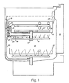
- a circulation circuit for a fluid which is pumped in a feed tube 10 which is branched into two spraying arms 11, 12 located in a washing cabinet 13 having an upper and a lower dish rack 14, 15 which can be pulled out through an opening in the front side of the machine provided with a door 16.
- the underside of the upper rack 14 is provided with a bearing 17 of the spraying arm 11 which bearing has a passage for a conduit 18 extended backwards along the underside of the rack.
- the conduit thus communicates with the spraying arm through the bearing so that the arm can rotate freely while the conduit stands still.
- the feed tube has a connecting surface 19 turned to the centre of the cabinet in which surface there is a port 20 through which the fluid can pass.
- the rear end of the conduit 18 forms a connecting house 21 extended in the vertical direction and terminated backwards by a couple of bellows 22, 23 which communicate with the conduit by holes 24, 25 in the wall.
- a couple of bellows 22, 23 which communicate with the conduit by holes 24, 25 in the wall.
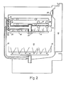
- One or the other of the bellows 22, 23 can be used to establish the connection, in Fig. 2 the bellows 23 are used, and the rack 14 is then in an upper working position in the washing cabinet.
- the rack 14 In use of the upper bellows (Fig. 1) the rack is in a lower working position. These positions are selectable and the selection is made with regard to the size of the dish goods.
- guides 26, 27 in the wall At each side of the rack there are guides 26, 27 in the wall, a lower one and an upper one. When the rack is pushed in on one of these pairs of guides, the corresponding bellows meet the port 20 so that connection to the feed tube is established.
- fluid passes through the feed tube 10 and the conduit 18 to the spraying arm 11.
- the bellows connected to the port are safely kept in position by a force directed to the feed tube and created by the closing of the door 16 by means of a shoulder 28 on the outer end of the rack, which shoulder is pushed by the door in the direction of the rack which transfers the force to the conduit 18 and the bellows.
- the advantages of a connecting device of this kind are principally its insensibility to deviations in the measures of the cabinet, the door, the racks, the feed tube etc.
- the flexible bellows (which also can be in the form of a sleeve, a collar or the like) will themselves adjust their outer tightening end to the connecting surface and thereby eliminate the risk of leakage.
Landscapes
- Washing And Drying Of Tableware (AREA)
- Cleaning In General (AREA)
Abstract
Description
- The present invention relates to a connecting device for a dish-washing machine as defined in the preamble of Claim 1.
- A connecting device of the kind referred to is disclosed in DE-A-2,355,271. In this device the conduit to the spraying arm has funnel-shaped connecting parts which cooperate with correspondingly shaped connecting protrusions arranged on the feed tube. The respective connecting parts and protrusions are loosely interconnected and to make possible the positioning of the rack at two different levels three protrusions are provided in a vertical row with the middle one being open and the two others being permanently closed. The conduit has two funnel-shaped parts and at each level one funnel-shaped part cooperates with the open protrusions whereas the other cooperates with one of the closed protrusions.
- The object of the invention is to simplify the connecting device by eliminating the protrusions and the funnel-shaped parts and to provide a tight connection between the conduit and the feed tube, thus eliminating any loss of liquid pressure that might appear in the prior art device referred to above.
- The object will be achieved in a device having the features stated in the characterizing part of Claim 1. A preferred embodiment is disclosed in Claim 2.
- An embodiment of a device according to the invention will be described by way of example in the following with reference to the accompanying drawings which show in
- Fig. 1 a dish-washing machine cabinet in a vertical cross-section and
- Fig. 2 the same cabinet having a rack in another position.
- In the dish-washing machine according to Fig. 1 there is a circulation circuit for a fluid which is pumped in a
feed tube 10 which is branched into two sprayingarms washing cabinet 13 having an upper and alower dish rack door 16. The underside of theupper rack 14 is provided with a bearing 17 of the sprayingarm 11 which bearing has a passage for aconduit 18 extended backwards along the underside of the rack. The conduit thus communicates with the spraying arm through the bearing so that the arm can rotate freely while the conduit stands still. The feed tube has a connectingsurface 19 turned to the centre of the cabinet in which surface there is aport 20 through which the fluid can pass. The rear end of theconduit 18 forms a connectinghouse 21 extended in the vertical direction and terminated backwards by a couple ofbellows holes port 20 and tightens against the connectingsurface 19. Theother bellows 23 abut the surface at the side of the port. When the fluid is caused to circulate in the machine a pressure arises which presses the outer ends of thebellows 22 harder to the connecting surface and the upper rack in direction to thedoor 16. The pressure of the fluid will then by itself provide a good tightening between thebellows 22 and the connectingsurface 19. One or the other of thebellows bellows 23 are used, and therack 14 is then in an upper working position in the washing cabinet. In use of the upper bellows (Fig. 1) the rack is in a lower working position. These positions are selectable and the selection is made with regard to the size of the dish goods. At each side of the rack there areguides port 20 so that connection to the feed tube is established. During the washing procedure fluid passes through thefeed tube 10 and theconduit 18 to the sprayingarm 11. The bellows connected to the port are safely kept in position by a force directed to the feed tube and created by the closing of thedoor 16 by means of ashoulder 28 on the outer end of the rack, which shoulder is pushed by the door in the direction of the rack which transfers the force to theconduit 18 and the bellows. When the door is opened and the rack pulled out the feed tube and the bellow are disconnected. - The advantages of a connecting device of this kind are principally its insensibility to deviations in the measures of the cabinet, the door, the racks, the feed tube etc. The flexible bellows (which also can be in the form of a sleeve, a collar or the like) will themselves adjust their outer tightening end to the connecting surface and thereby eliminate the risk of leakage.
Claims (2)
Priority Applications (1)
| Application Number | Priority Date | Filing Date | Title |
|---|---|---|---|
| AT82903489T ATE16887T1 (en) | 1981-11-24 | 1982-11-18 | CONNECTING DEVICE. |
Applications Claiming Priority (2)
| Application Number | Priority Date | Filing Date | Title |
|---|---|---|---|
| SE8106996A SE442703B (en) | 1981-11-24 | 1981-11-24 | CLUTCH DEVICE FOR A DISHWASHER ORGANIZED RINSE SYSTEM |
| SE8106996 | 1981-11-24 |
Publications (2)
| Publication Number | Publication Date |
|---|---|
| EP0094409A1 EP0094409A1 (en) | 1983-11-23 |
| EP0094409B1 true EP0094409B1 (en) | 1985-12-11 |
Family
ID=20345116
Family Applications (1)
| Application Number | Title | Priority Date | Filing Date |
|---|---|---|---|
| EP82903489A Expired EP0094409B1 (en) | 1981-11-24 | 1982-11-18 | A connecting device |
Country Status (6)
| Country | Link |
|---|---|
| EP (1) | EP0094409B1 (en) |
| DE (1) | DE3267942D1 (en) |
| DK (1) | DK149641C (en) |
| FI (1) | FI77367C (en) |
| SE (1) | SE442703B (en) |
| WO (1) | WO1983001892A1 (en) |
Cited By (2)
| Publication number | Priority date | Publication date | Assignee | Title |
|---|---|---|---|---|
| DE4137227C2 (en) * | 1991-11-13 | 1999-12-16 | Aeg Hausgeraete Gmbh | Household dishwasher with height-adjustable upper basket |
| US9386904B2 (en) | 2010-11-18 | 2016-07-12 | Whirlpool Corporation | Dishwasher with movable liquid conduit |
Families Citing this family (20)
| Publication number | Priority date | Publication date | Assignee | Title |
|---|---|---|---|---|
| IT1227581B (en) * | 1988-11-28 | 1991-04-16 | Merloni Elettrodomestici Spa | DISHWASHER MACHINE WITH VARIABLE LOAD POSSIBILITY |
| IT1234696B (en) * | 1989-06-06 | 1992-05-26 | Zanussi A Spa Industrie | DISHWASHER WITH REMOVABLE HEIGHT-ADJUSTABLE BASKET. |
| IT1282096B1 (en) * | 1996-01-29 | 1998-03-12 | Smeg Spa | HYDRAULIC CONNECTION DEVICE FOR DISHWASHER BASKET POSITIONABLE AT TWO DIFFERENT HEIGHTS |
| DE19611054A1 (en) * | 1996-03-20 | 1997-09-25 | Bosch Siemens Hausgeraete | dishwasher |
| IT1284791B1 (en) * | 1996-09-11 | 1998-05-21 | Merloni Elettrodomestici Spa | IMPROVED HYDRAULIC CIRCUIT DISHWASHER. |
| IT1289970B1 (en) * | 1997-02-25 | 1998-10-19 | Smeg Spa | HYDRAULIC CONNECTION DEVICE FOR DISHWASHER BASKET POSITIONABLE AT TWO DIFFERENT HEIGHTS |
| IT1290112B1 (en) * | 1997-03-18 | 1998-10-19 | Smeg Spa | HYDRAULIC CELL-CONNECTION DEVICE FOR DISHWASHER BASKET POSITIONABLE AT TWO DIFFERENT HEIGHTS |
| IT1301741B1 (en) * | 1998-06-18 | 2000-07-07 | Candy Spa | DISHWASHER MACHINE WITH HEIGHT ADJUSTABLE BASKET. |
| US6431188B1 (en) | 2000-04-03 | 2002-08-13 | Whirlpool Corporation | Dishwasher spray arm feed system |
| KR100413441B1 (en) * | 2001-06-09 | 2003-12-31 | 엘지전자 주식회사 | Washer for medical equipment |
| DE102007003894B4 (en) * | 2007-01-19 | 2008-09-04 | Miele & Cie. Kg | Dishwasher, Spülgutträger and system of a dishwasher and a Spülgutträger |
| DE102007041307A1 (en) * | 2007-08-31 | 2009-03-05 | BSH Bosch und Siemens Hausgeräte GmbH | dishwasher |
| US8166983B2 (en) | 2007-12-21 | 2012-05-01 | Wolf Appliance, Inc. | Fluid supply system for appliance |
| DE102008016485A1 (en) | 2008-03-31 | 2009-10-01 | BSH Bosch und Siemens Hausgeräte GmbH | dishwasher |
| DE102008020887A1 (en) * | 2008-04-25 | 2009-10-29 | BSH Bosch und Siemens Hausgeräte GmbH | Dishwasher and floor pan for such a dishwasher |
| RU2520044C2 (en) * | 2009-06-23 | 2014-06-20 | Электролюкс Хоум Продактс Корпорейшн Н.В. | Dishwashing machine, in particular, household dishwashing machine |
| EP3040011B1 (en) | 2014-12-31 | 2019-07-24 | Whirlpool EMEA S.p.A | Household dish-washing machine |
| EP3040010B1 (en) | 2014-12-31 | 2017-08-02 | Whirlpool EMEA S.p.A | Household dish-washing machine |
| EP3040012B1 (en) | 2014-12-31 | 2018-12-12 | Whirlpool EMEA S.p.A | Dishwashing machine |
| EP3197334B1 (en) * | 2015-07-20 | 2019-09-04 | LG Electronics Inc. | Dishwasher |
Family Cites Families (4)
| Publication number | Priority date | Publication date | Assignee | Title |
|---|---|---|---|---|
| FI51736C (en) * | 1969-02-19 | 1977-03-10 | Sarlin Ab Oy E | Equipment for use in septic tanks or other such accessible basins to connect a pipe that can be removed from the basin and a pipe that is permanently connected to the basin wall |
| DE2355271A1 (en) * | 1973-11-06 | 1975-05-07 | Licentia Gmbh | Dishwasher with spray arm feed pipe - is loosely coupled to water feed duct attached fast to housing |
| DE2732540C2 (en) * | 1977-07-19 | 1983-01-05 | Bosch-Siemens Hausgeräte GmbH, 7000 Stuttgart | A crockery basket with a spray arm that can be inserted into the washing compartment of a dishwasher at two different heights |
| DE2732665C2 (en) * | 1977-07-20 | 1983-01-05 | Bosch-Siemens Hausgeräte GmbH, 7000 Stuttgart | A crockery basket with a spray arm that can be inserted into the washing compartment of a dishwasher at different heights |
-
1981
- 1981-11-24 SE SE8106996A patent/SE442703B/en unknown
-
1982
- 1982-11-18 EP EP82903489A patent/EP0094409B1/en not_active Expired
- 1982-11-18 DE DE8282903489T patent/DE3267942D1/en not_active Expired
- 1982-11-18 WO PCT/SE1982/000389 patent/WO1983001892A1/en not_active Ceased
-
1983
- 1983-07-15 DK DK327683A patent/DK149641C/en not_active IP Right Cessation
- 1983-07-22 FI FI832667A patent/FI77367C/en not_active IP Right Cessation
Cited By (2)
| Publication number | Priority date | Publication date | Assignee | Title |
|---|---|---|---|---|
| DE4137227C2 (en) * | 1991-11-13 | 1999-12-16 | Aeg Hausgeraete Gmbh | Household dishwasher with height-adjustable upper basket |
| US9386904B2 (en) | 2010-11-18 | 2016-07-12 | Whirlpool Corporation | Dishwasher with movable liquid conduit |
Also Published As
| Publication number | Publication date |
|---|---|
| DK327683D0 (en) | 1983-07-15 |
| FI832667L (en) | 1983-07-22 |
| DE3267942D1 (en) | 1986-01-23 |
| EP0094409A1 (en) | 1983-11-23 |
| DK327683A (en) | 1983-07-15 |
| SE442703B (en) | 1986-01-27 |
| SE8106996L (en) | 1983-05-25 |
| FI77367B (en) | 1988-11-30 |
| FI832667A0 (en) | 1983-07-22 |
| DK149641B (en) | 1986-08-25 |
| WO1983001892A1 (en) | 1983-06-09 |
| DK149641C (en) | 1987-02-09 |
| FI77367C (en) | 1989-03-10 |
Similar Documents
| Publication | Publication Date | Title |
|---|---|---|
| WO1983001892A1 (en) | A connecting device | |
| US9421546B2 (en) | Universal shelving system | |
| US9004085B2 (en) | Dishwashing machine | |
| DE3569661D1 (en) | Cleaning apparatus for dry or wet suction and/or for rinse extraction cleaning | |
| WO2000033720A3 (en) | Household dishwasher | |
| US20160242868A1 (en) | Apparatus for cleaning medical instruments | |
| CN106885084B (en) | Multi-fitting manifold for quick connector | |
| CA2118514A1 (en) | Flexible Connector Assembly | |
| US3463173A (en) | Machines for washing laboratory equipment such as flasks,bottles,test tubes and similar articles | |
| DE60218571T2 (en) | Device for cleaning medical devices | |
| US2881010A (en) | Detachable connector for milking systems or the like | |
| DE3773851D1 (en) | CLEANING DEVICE FOR DISPENSING SYSTEMS AND DEVICE FOR AUTOMATIC CHANGING OF BARRELS. | |
| GB2001523A (en) | Dish washing machine | |
| US3011755A (en) | Milk pipeline valve | |
| GB2001522A (en) | Crockery container for dishwashing machine | |
| JP7393950B2 (en) | Milk module for producing milk foam or milk drinks, preferably for installation in a coffee machine | |
| WO2017014491A1 (en) | Dishwasher | |
| CA2185997C (en) | Pipework for sprinkler systems | |
| ITBO990688A1 (en) | DISHWASHER. | |
| US5415192A (en) | Cleaning device for a milking plant | |
| US3941153A (en) | Water inlet device for controlling flow to an appliance | |
| NO157241B (en) | CONNECTION DEVICE. | |
| EP3037108A1 (en) | System for the fast connection of a pipe to an outlet and the automatic closing of the outlet in the absence of the pipe | |
| GB1017567A (en) | Improvements in or relating to methods of and/or apparatus for flushing the teat cups of milking machines | |
| US4376454A (en) | Valve |
Legal Events
| Date | Code | Title | Description |
|---|---|---|---|
| PUAI | Public reference made under article 153(3) epc to a published international application that has entered the european phase |
Free format text: ORIGINAL CODE: 0009012 |
|
| 17P | Request for examination filed |
Effective date: 19830711 |
|
| AK | Designated contracting states |
Designated state(s): AT BE CH DE FR GB LI NL |
|
| GRAA | (expected) grant |
Free format text: ORIGINAL CODE: 0009210 |
|
| AK | Designated contracting states |
Designated state(s): AT BE CH DE FR GB LI NL |
|
| REF | Corresponds to: |
Ref document number: 16887 Country of ref document: AT Date of ref document: 19851215 Kind code of ref document: T |
|
| REF | Corresponds to: |
Ref document number: 3267942 Country of ref document: DE Date of ref document: 19860123 |
|
| ET | Fr: translation filed | ||
| PLBE | No opposition filed within time limit |
Free format text: ORIGINAL CODE: 0009261 |
|
| STAA | Information on the status of an ep patent application or granted ep patent |
Free format text: STATUS: NO OPPOSITION FILED WITHIN TIME LIMIT |
|
| 26N | No opposition filed | ||
| PGFP | Annual fee paid to national office [announced via postgrant information from national office to epo] |
Ref country code: AT Payment date: 19951113 Year of fee payment: 14 |
|
| PGFP | Annual fee paid to national office [announced via postgrant information from national office to epo] |
Ref country code: NL Payment date: 19951129 Year of fee payment: 14 |
|
| PGFP | Annual fee paid to national office [announced via postgrant information from national office to epo] |
Ref country code: BE Payment date: 19960109 Year of fee payment: 14 |
|
| PG25 | Lapsed in a contracting state [announced via postgrant information from national office to epo] |
Ref country code: AT Effective date: 19961118 |
|
| PG25 | Lapsed in a contracting state [announced via postgrant information from national office to epo] |
Ref country code: BE Effective date: 19961130 |
|
| BERE | Be: lapsed |
Owner name: A.B. ELECTROLUX Effective date: 19961130 |
|
| PG25 | Lapsed in a contracting state [announced via postgrant information from national office to epo] |
Ref country code: NL Effective date: 19970601 |
|
| NLV4 | Nl: lapsed or anulled due to non-payment of the annual fee |
Effective date: 19970601 |
|
| PGFP | Annual fee paid to national office [announced via postgrant information from national office to epo] |
Ref country code: FR Payment date: 20011113 Year of fee payment: 20 |
|
| PGFP | Annual fee paid to national office [announced via postgrant information from national office to epo] |
Ref country code: GB Payment date: 20011121 Year of fee payment: 20 |
|
| PGFP | Annual fee paid to national office [announced via postgrant information from national office to epo] |
Ref country code: CH Payment date: 20011130 Year of fee payment: 20 |
|
| PGFP | Annual fee paid to national office [announced via postgrant information from national office to epo] |
Ref country code: DE Payment date: 20011203 Year of fee payment: 20 |
|
| REG | Reference to a national code |
Ref country code: GB Ref legal event code: IF02 |
|
| PG25 | Lapsed in a contracting state [announced via postgrant information from national office to epo] |
Ref country code: LI Free format text: LAPSE BECAUSE OF EXPIRATION OF PROTECTION Effective date: 20021117 Ref country code: GB Free format text: LAPSE BECAUSE OF EXPIRATION OF PROTECTION Effective date: 20021117 Ref country code: CH Free format text: LAPSE BECAUSE OF EXPIRATION OF PROTECTION Effective date: 20021117 |
|
| REG | Reference to a national code |
Ref country code: GB Ref legal event code: PE20 Effective date: 20021117 |
|
| REG | Reference to a national code |
Ref country code: CH Ref legal event code: PL |