EP0094319B1 - Rhéomètre à cylindres pour mesures sous pression et température élevées avec prélèvements d'échantillons - Google Patents
Rhéomètre à cylindres pour mesures sous pression et température élevées avec prélèvements d'échantillons Download PDFInfo
- Publication number
- EP0094319B1 EP0094319B1 EP83400945A EP83400945A EP0094319B1 EP 0094319 B1 EP0094319 B1 EP 0094319B1 EP 83400945 A EP83400945 A EP 83400945A EP 83400945 A EP83400945 A EP 83400945A EP 0094319 B1 EP0094319 B1 EP 0094319B1
- Authority
- EP
- European Patent Office
- Prior art keywords
- rotor
- rheometer
- shaft
- zone
- stirrer
- Prior art date
- Legal status (The legal status is an assumption and is not a legal conclusion. Google has not performed a legal analysis and makes no representation as to the accuracy of the status listed.)
- Expired
Links
Images

Classifications
-
- G—PHYSICS
- G01—MEASURING; TESTING
- G01N—INVESTIGATING OR ANALYSING MATERIALS BY DETERMINING THEIR CHEMICAL OR PHYSICAL PROPERTIES
- G01N11/00—Investigating flow properties of materials, e.g. viscosity, plasticity; Analysing materials by determining flow properties
- G01N11/10—Investigating flow properties of materials, e.g. viscosity, plasticity; Analysing materials by determining flow properties by moving a body within the material
- G01N11/14—Investigating flow properties of materials, e.g. viscosity, plasticity; Analysing materials by determining flow properties by moving a body within the material by using rotary bodies, e.g. vane
-
- B—PERFORMING OPERATIONS; TRANSPORTING
- B01—PHYSICAL OR CHEMICAL PROCESSES OR APPARATUS IN GENERAL
- B01J—CHEMICAL OR PHYSICAL PROCESSES, e.g. CATALYSIS OR COLLOID CHEMISTRY; THEIR RELEVANT APPARATUS
- B01J2219/00—Chemical, physical or physico-chemical processes in general; Their relevant apparatus
- B01J2219/00049—Controlling or regulating processes
- B01J2219/00168—Controlling or regulating processes controlling the viscosity
Definitions
- the subject of the invention is a rheometer of the cylinder type specially intended for carrying out measurements of rheological properties in an environment whose homogeneity must be maintained with certainty and which is capable of being held under pressure and brought to a high temperature.
- Such a rheometer is necessary during certain researches such as those relating to the hydroliquefaction of products such as coal, woody materials or heavy petroleum residues.
- This operation is carried out by hydrogenation in the liquid phase: pulverized product (coal for example) is mixed with oil to give a paste which is circulated in a series of reactors under hydrogen pressure, the temperature is progressively higher during the journey.
- the main object of the invention is to provide a rheometer with cylinders which allows measurements of rheological properties in a medium whose homogeneity is well preserved, therefore without risk of solidification in the air gap of the medium subjected to the measurement in the case of the hydrogenation of the coal mentioned above, at various temperature and pressure conditions.
- the invention has, as a secondary object, to achieve a rotor rheometer with which samples of liquid phase and vapor phase are possible just before or after the execution of a viscosity measurement, without disturbing this measurement.
- Document US Pat. No. 3,056,283 discloses an apparatus for measuring the viscosity of molten glass; this apparatus comprises an oven in which a creusef open at its upper end contains molten glass; a cylinder suspended from a rotating shaft can be immersed in the molten glass; this cylinder is rotated by means of a spring; the resistive torque opposed by the molten glass to the rotation of the cylinder causes a deformation of the spring which is used to measure the viscosity of the glass.
- This device does not allow working under pressure, nor to take samples of a liquid phase and a gaseous phase just at the time of viscosity measurements.
- Document DE-B-1 184119 also discloses an apparatus for the continuous measurement of the viscosity of a liquid held under pressure or under vacuum.
- An airtight enclosure contains a vertical shaft guided in an upper bearing and in a lower bearing; on this shaft are wedged a rotor embedded in the liquid and a first magnet located above the liquid.
- This same shaft also carries, at its upper end, a second magnet which is used to produce a magnetic coupling in rotation through the wall of the enclosure with a third magnet driven in rotation; the viscosity of the liquid brakes the rotor and produces a phase shift in the magnetic coupling which is measured by means of the second magnet.
- This device makes it possible to move the rotor on the shaft to immerse it in the liquid just at the time of a measurement; nor does it allow samples to be taken from a liquid phase and a gaseous phase.
- a rotor rheometer comprises a hollow body with an internal volume in the bottom of which is provided a first bearing, a cap for closing the hollow body, said cap comprising a second bearing, an internal vertical shaft held by said first and second bearings on which said rotor is mounted, means for driving this shaft in rotation by means of a torque measurement means, and it is characterized in that the internal volume includes a lower zone intended to constitute the fixed measuring cylinder and an upper zone of enlarged diameter with respect to the lower zone and of height at least equal to that of the rotor, the latter being displaceable in translation in the longitudinal direction along the shaft between an upper position in which it is in the upper zone and a lower position in which it is in the lower zone for the execution of a measurement.
- Means are provided for moving the rotor along the inner shaft. Preferably, these means are associated with the rotor and the inner shaft.
- the rotor is hollow and the internal shaft is provided in the lower zone with an agitator which it drives in rotation, said agitator having a diameter less than the internal diameter of the hollow rotor, so that this agitator can be contained in the rotor.
- the agitator is locked in translation in said longitudinal direction, in the lower part of the shaft interior contained in the lower area of the interior volume.
- the means of displacement in the longitudinal direction of the rotor comprise a thread provided on the inner shaft in its part located in the upper zone of the interior volume and a nut fixed to the rotor, the direction of the thread being such that a rotation in the opposite direction to the direction of execution of a measurement causes the rotor to move to its upper position.
- the direction of the thread is such that, when the inner shaft is rotated in the opposite direction to the direction of execution of the viscosity measurements, the nut is screwed onto this shaft and the rotor rises up to the upper half on exiting totally from the air gap area.
- the rotor is movable between a lower position where it is used for the execution of rheological properties measurements and a higher position in which it is no longer used to limit the air gap.
- a hole In the wall of the lower zone of the hollow body is drilled a hole in which is mounted a needle pushed against a seat close to the inner face of the hollow body.
- a groove In the lateral face of this needle, behind its head, a groove is hollowed in correspondence with two spaced channels which extend laterally through the wall of the hollow body to its outer face.
- the needle is applied against the seat by an elastic element to allow its opening.
- the valve stem In the wall of the upper zone of the hollow body is hollowed out a lateral chamber from which is drilled a hole containing a valve whose seat is the orifice of this hole opening into this lateral chamber. Behind its head, the valve stem has in its lateral face a groove matched with two spaced channels which extend laterally through the wall of the hollow body to its outer face.
- the valve is applied against its seat by an elastic element to allow its opening.
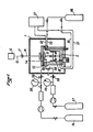
- the rheometer of the invention is disposed inside an enclosure 1 at constant temperature around which there are various peripheral devices.
- It comprises a hollow body 2 having an interior volume 3 in which there is a lower zone 3A which serves as a fixed cylinder and an upper zone 3B of enlarged diameter, with an upper opening which can be hermetically sealed by means of a cap 4. The latter is held in place by screws 5 which allow to crush a seal 6 ensuring the seal.
- a bearing 7 and in the cap 4 a bearing 8 which maintain in the axis of the hollow body 1 and the interior volume 3 a vertical inner shaft 9.
- the interior shaft 9 is provided with an agitator 10 with blades 11, locked in rotation and in longitudinal displacement.
- the inner shaft 9 is provided with a hub 1.2 which carries several magnets 12A spaced radially and circularly below the cap 4. Above this are mounted in correspondence of the magnets 13 carried by an outer shaft 14. A magnetic coupling is thus obtained in rotation through the cap 4 which is made of suitable material.
- the magnets are preferably made of TICONAL so as to retain good magnetic properties at 550 ° C.
- the outer shaft 14 is itself rotatably coupled to the shaft 15 of a motor 16 by means of a spiral spring 17 associated with a reading scale (not shown) for measuring the drive torque inner shaft 9.
- a hollow rotary cylinder or rotor 18 is mounted on this inner shaft 9 with the possibility of displacement in the longitudinal direction between a lower position and an upper position.
- the rotor 18 In its upper position, the rotor 18 is completely included in the upper zone 3B with an enlarged diameter whose height is at least equal to that of the rotor. At its lower position the latter is included in the lower zone 3A where the hollow body 2 serves as a fixed cylinder and limits with the rotor 18 uri air gap 19, as is known in viscometers with rotating cylinder.
- the displacement of the rotor 18 can be done by any suitable means; in this example, the upper part of the inner shaft 9 carries a thread 20 and the rotor 18 comprises a nut 21.
- the direction of the thread is such that when the shaft 9 is rapidly rotated in the opposite direction to the direction of rotation from the viscosity measurement, the nut 21 is screwed onto the thread 20 and the rotor 18 rises to its upper position, until it meets the hub 12.
- the lower zone 3A which serves as a fixed cylinder is completely free , with the exception of the agitator 10 which remains in place and which creates strong agitation in the liquid phase therein.
- the rotor 18 descends into the lower zone 3A until it meets the hub of the agitator 10.
- the air gap 19 is then established and the measurement can be carried out in a homogeneous phase.
- the agitator which has a diameter smaller than the inside diameter of the hollow rotor 18 is then included in the latter.
- a channel 22 ending in the interior volume 3 by a smaller orifice 23 so as to provide a seat 24 for a needle 25 which extends outside and which is pushed back into the closed position by several elastic washers 26 retained by a stirrup 27.
- the needle 25 is slidably mounted in a plug 28 which crushes an annular seal 29 and it is surrounded by a seal toric 30.
- An enlargement 31 is provided on the needle 25 outside the plug 28 to serve as a bearing surface for the elastic washers 26 and to allow it to be maneuvered in the direction of opening against the thrust of the latter.
- the needle 25 has, in its lateral face, a longitudinal groove 32 opposite which two spaced transverse channels 33, 34 are drilled through the wall of the hollow body 1 to its face outside for connection to two pipes 35, 36 which lead respectively to an analysis apparatus 37 and to a source of fluid 38.
- a lateral chamber 39 is formed in the thickness of the wall into which a hole 40 opens, drilled in a longitudinal direction from the lower external face of the hollow body 2.
- the orifice of the hole 40 serves as a seat 41 to a valve 42 extended by a spindle 43 which slides in a plug 44.
- the latter crushes an annular seal 45 and contains an O-ring 46 which seal the mounting of the spindle 43.
- the latter ends with a widening 47 for retain elastic washers 48 which bear against the plug 44.
- the stem thereof has a longitudinal groove 49 and two spaced transverse channels 50, 51 are drilled through the wall of the hollow body 2 to allow their connection to two pipes 52, 53 which lead respectively to the analysis apparatus 37 and to the fluid source 38.
- a transverse hole 54 is drilled through the wall at the upper half 3B of the interior volume 3; it is connected to a pipe 55 which leads to two sources of pressurized gas 56, 57 and on which there are valves 58 and pressure gauges 59.
- the desired gases are therefore easily introduced into the hollow body 2 in order to establish the desired pressure therein. , after having filled it with solid substance and having hermetically closed the cap 4. Any measurement of rheological property may be preceded by a period of homogenization of the phase or of the mixture of phases contained in the lower zone 3A, at the using the agitator 10 while the rotor 18 occupies its upper position, as explained above.
- a sample can be taken at any time, in the upper zone 3B as well as in the lower zone 3A. Just pull the needle 25 or lift the valve 42 for a very short time: a percussion produced in the desired direction is sufficient.
- the sample which escapes fills the groove 32 or 49.
- a fluid serving as a vector is sent by one of the transverse channels 34 or 51 and collected with the sample by the other of the transverse channels 33 or 50, coming from from the fluid source 38 to the analysis apparatus 37.
- An apparatus as described above is very useful for determining the quantities necessary for the design of processes working at high temperature and / or high pressure.
Landscapes
- Physics & Mathematics (AREA)
- Health & Medical Sciences (AREA)
- Life Sciences & Earth Sciences (AREA)
- Chemical & Material Sciences (AREA)
- Analytical Chemistry (AREA)
- Biochemistry (AREA)
- General Health & Medical Sciences (AREA)
- General Physics & Mathematics (AREA)
- Immunology (AREA)
- Pathology (AREA)
- Sampling And Sample Adjustment (AREA)
- Adhesives Or Adhesive Processes (AREA)
- Mixers Of The Rotary Stirring Type (AREA)
- Investigating Or Analysing Biological Materials (AREA)
Priority Applications (1)
| Application Number | Priority Date | Filing Date | Title |
|---|---|---|---|
| AT83400945T ATE19305T1 (de) | 1982-05-11 | 1983-05-10 | Rotationsrheometer zum durchfuehren von messungen unter hohen temperatur- und druckverhaeltnissen mit probennahmevorrichtung. |
Applications Claiming Priority (2)
| Application Number | Priority Date | Filing Date | Title |
|---|---|---|---|
| FR8208160A FR2526946A1 (fr) | 1982-05-11 | 1982-05-11 | Viscometre a cylindres pour mesures sous pression et temperature elevees avec prelevements d'echantillons |
| FR8208160 | 1982-05-11 |
Publications (2)
| Publication Number | Publication Date |
|---|---|
| EP0094319A1 EP0094319A1 (fr) | 1983-11-16 |
| EP0094319B1 true EP0094319B1 (fr) | 1986-04-16 |
Family
ID=9273913
Family Applications (1)
| Application Number | Title | Priority Date | Filing Date |
|---|---|---|---|
| EP83400945A Expired EP0094319B1 (fr) | 1982-05-11 | 1983-05-10 | Rhéomètre à cylindres pour mesures sous pression et température élevées avec prélèvements d'échantillons |
Country Status (5)
| Country | Link |
|---|---|
| US (1) | US4524611A (OSRAM) |
| EP (1) | EP0094319B1 (OSRAM) |
| AT (1) | ATE19305T1 (OSRAM) |
| DE (1) | DE3363024D1 (OSRAM) |
| FR (1) | FR2526946A1 (OSRAM) |
Families Citing this family (36)
| Publication number | Priority date | Publication date | Assignee | Title |
|---|---|---|---|---|
| JPS61502488A (ja) * | 1984-06-22 | 1986-10-30 | ル−ファ−、ディ−タ− アレックス | レオロジ−特性の測定装置 |
| FR2569850B1 (fr) * | 1984-08-31 | 1987-09-11 | Petroles Cie Francaise | Recipient pour matiere rheologiquement evolutive, utilisable dans un consistometre d'analyse d'evolution rheologique |
| US4879897A (en) * | 1985-08-19 | 1989-11-14 | Commonwealth Scientific And Industrial Research Organization | Method and apparatus for the determination of viscosity |
| US4760734A (en) * | 1986-02-07 | 1988-08-02 | Bryce Maxwell | Apparatus for measuring the rheological properties of materials |
| FR2594950B1 (fr) * | 1986-02-27 | 1988-05-06 | Petroles Cie Francaise | Consistometre d'analyse d'evolution rheologique, notamment utilisable sur un chantier |
| SE461058B (sv) * | 1987-09-04 | 1989-12-18 | Btg Kaelle Inventing Ab | Anordning vid en viskositetsmaetare |
| US4829811A (en) * | 1988-04-08 | 1989-05-16 | Halliburton Company | Fluid testing apparatus and method |
| US5357785A (en) * | 1993-06-04 | 1994-10-25 | Radian Corporation | Method and device for determining rhenological properties |
| US5321974A (en) * | 1993-06-04 | 1994-06-21 | Radian Corporation | Method and device for determining rheological properties |
| SE503681C2 (sv) * | 1994-11-21 | 1996-07-29 | Reologica Instr Ab | Reologiskt mätaggregat |
| US6231646B1 (en) | 1999-03-11 | 2001-05-15 | Chemco Manufacturing Company, Inc. | Paint overspray exhaust air filter |
| US6257051B1 (en) | 1999-03-11 | 2001-07-10 | The Lubrizol Corporation | On-board rotational viscometers |
| US6571609B1 (en) | 2001-05-09 | 2003-06-03 | Hongfeng Bi | Digital viscometer with arm and force sensor to measure torque |
| US6629451B1 (en) | 2002-04-16 | 2003-10-07 | Halliburton Energy Services, Inc. | Method for determining the rheology of a gelled fluid |
| US6952950B2 (en) * | 2003-03-07 | 2005-10-11 | Waters Investment Limited | System and method for automatic identification of a detachable component of an instrument |
| US6798099B1 (en) | 2003-07-14 | 2004-09-28 | Waters Investment Limited | Devices, systems and methods for sensing temperature of a drag cup in a rheometer motor |
| US7017393B2 (en) * | 2004-03-11 | 2006-03-28 | Waters Investment Limited | Rotary rheometer magnetic bearing |
| GB0419152D0 (en) * | 2004-08-27 | 2004-09-29 | Kernow Instr Technology Ltd | A contactless magnetic rotary bearing and a rheometer incorporating such bearing |
| US7287416B1 (en) | 2005-10-24 | 2007-10-30 | Hongfeng Bi | Low maintenance high pressure viscometer |
| US7412877B1 (en) | 2005-10-24 | 2008-08-19 | Hongfeng Bi | High pressure viscometer with chamber preventing sample contamination |
| US7992427B2 (en) * | 2008-07-02 | 2011-08-09 | Halliburton Energy Services Inc., | Device and method for testing friction reduction efficiency and suspension systems |
| US8024962B2 (en) * | 2008-07-28 | 2011-09-27 | Halliburton Energy Services Inc. | Flow-through apparatus for testing particle laden fluids and methods of making and using same |
| US8230723B2 (en) * | 2008-09-19 | 2012-07-31 | Chandler Instruments Company, LLC | High pressure high temperature viscometer |
| US8375771B1 (en) | 2010-05-21 | 2013-02-19 | Hongfeng Bi | Viscometer for testing cement rheology |
| CN101949808B (zh) * | 2010-07-30 | 2012-07-04 | 中海油田服务股份有限公司 | 稠化仪新型水泥浆稠度测量装置 |
| US8347693B2 (en) * | 2010-08-26 | 2013-01-08 | Halliburton Energy Services, Inc. | Apparatus and methods for continuous compatibility testing of subterranean fluids and their compositions under wellbore conditions |
| US8850874B1 (en) | 2012-01-05 | 2014-10-07 | Hongfeng Bi | In-line viscometer |
| CN103217362B (zh) * | 2013-03-15 | 2015-06-24 | 中国海洋石油总公司 | 一种钻井液流变性测量装置及测量方法 |
| CN103674783A (zh) * | 2013-12-20 | 2014-03-26 | 上海应用技术学院 | 双线圈磁流变液性能测试装置 |
| AT521097B1 (de) * | 2018-03-26 | 2022-05-15 | Anton Paar Gmbh | Rotationsviskosimeter zur Messung der Viskosität von Stoffen |
| CN108827829A (zh) * | 2018-04-19 | 2018-11-16 | 辽宁石油化工大学 | 一种基于膨润土造浆率公式的造浆率测量方法与装置 |
| DE102018122023A1 (de) * | 2018-09-10 | 2020-03-12 | Brabender Gmbh & Co. Kg | Rheometer |
| AT522030B1 (de) * | 2018-12-21 | 2022-07-15 | Anton Paar Gmbh | Messantrieb mit Ultraschall-gelagerter Welle, Rheometer,, Verfahren und Verwenden |
| US12174102B2 (en) * | 2019-01-31 | 2024-12-24 | Halliburton Energy Services, Inc. | Optical fluidic methods for a rheometer |
| US11313740B2 (en) | 2019-02-08 | 2022-04-26 | Fairfield Manufacturing Company, Inc. | Gearbox temperature measurement device |
| WO2021076400A1 (en) * | 2019-10-15 | 2021-04-22 | Ta Instruments-Waters Llc | Rotor for rheological measurements of material with variable volume |
Family Cites Families (6)
| Publication number | Priority date | Publication date | Assignee | Title |
|---|---|---|---|---|
| US2484761A (en) * | 1945-04-05 | 1949-10-11 | American Cyanamid Co | Viscosimeter |
| US3056283A (en) * | 1959-06-23 | 1962-10-02 | Owens Corning Fiberglass Corp | Apparatus for measuring the viscosity of glass at high temperatures |
| DE1184119B (de) * | 1960-02-03 | 1964-12-23 | Bayer Ag | Verfahren zur kontinuierlichen Messung von Viskositaetsaenderungen im Innern von Hochdruck- oder Vakuumbehaeltern |
| US3216243A (en) * | 1962-11-23 | 1965-11-09 | Bergfelt Allan | Apparatus for determination of the internal resistance of a mass |
| US3435666A (en) * | 1966-07-18 | 1969-04-01 | Champion Lab Inc | Viscometer |
| US3935729A (en) * | 1975-01-27 | 1976-02-03 | Armstrong Cork Company | Gap filler for rheometer |
-
1982
- 1982-05-11 FR FR8208160A patent/FR2526946A1/fr active Granted
-
1983
- 1983-05-10 AT AT83400945T patent/ATE19305T1/de not_active IP Right Cessation
- 1983-05-10 US US06/493,411 patent/US4524611A/en not_active Expired - Fee Related
- 1983-05-10 EP EP83400945A patent/EP0094319B1/fr not_active Expired
- 1983-05-10 DE DE8383400945T patent/DE3363024D1/de not_active Expired
Also Published As
| Publication number | Publication date |
|---|---|
| US4524611A (en) | 1985-06-25 |
| FR2526946A1 (fr) | 1983-11-18 |
| DE3363024D1 (en) | 1986-05-22 |
| FR2526946B1 (OSRAM) | 1984-12-21 |
| EP0094319A1 (fr) | 1983-11-16 |
| ATE19305T1 (de) | 1986-05-15 |
Similar Documents
| Publication | Publication Date | Title |
|---|---|---|
| EP0094319B1 (fr) | Rhéomètre à cylindres pour mesures sous pression et température élevées avec prélèvements d'échantillons | |
| CA2577892C (fr) | Dispositif et methode de mesures thermodynamiques sur des fluides petroliers | |
| FR2940439A1 (fr) | Dispositif pour le transfert d'un milieu | |
| FR2765338A1 (fr) | Dispositif de prelevement et/ou d'injection d'un echantillon de fluide permettant de conserver l'equilibre chimique et/ou thermodynamique | |
| FR2484077A1 (fr) | Procede et dispositif de mesure de la deformabilite de cellules vivantes, notamment des globules rouges du sang | |
| FR2737780A1 (fr) | Cellule d'essai de melanges fluides adaptee a detecter des changements de phases | |
| FR2587800A1 (fr) | Procede et dispositif de mesure du point de bulle du petrole d'une formation souterraine | |
| FR2563913A1 (fr) | Dispositif de prelevement et de conditionnement d'echantillons de materiaux sous forme solide, liquide ou gazeuse en vue de leur analyse | |
| CH617252A5 (OSRAM) | ||
| EP2220209A1 (fr) | Dispositif de broyage d'un échantillon biologique | |
| FR2594950A1 (fr) | Consistometre d'analyse d'evolution rheologique, notamment utilisable sur un chantier | |
| FR2678381A1 (fr) | Consistometre. | |
| EP2179787A1 (fr) | Appareillage à cuve d'agitation | |
| EP0613955B1 (fr) | Dispositif de chargement avec organe de réglage du débit | |
| EP2877825B1 (fr) | Cellule de mesure calorimetrique haute pression | |
| FR2470320A1 (fr) | Robinet de prise d'echantillons avec indicateur de la position du piston | |
| FR2655145A1 (en) | Bottle for transporting a fluid sample, in particular of hydrocarbon | |
| FR2856797A1 (fr) | Dispositif et methode de mesures thermodynamiques sur des fluides petroliers | |
| EP1336831B1 (fr) | Appareil de mesure du débit de fuite d'un dispositif d'étanchéité | |
| FR2656694A1 (fr) | Dispositif de prelevement de liquide. | |
| WO2000006453A1 (fr) | Dispositif de distribution, notamment pour doseur de machine de remplissage, et doseur equipe d'un tel dispositif | |
| US3087339A (en) | Automatic sampler | |
| FR2459073A1 (fr) | Appareil de laboratoire pour preparation sous vide d'emulsions et suspensions fines | |
| EP0271401B1 (fr) | Dispositif pour la vidange de réacteurs de laboratoire | |
| FR2479466A1 (fr) | Dispositif d'injection d'echantillons d'un produit gazeux ou liquide sous pression en vue d'analyse |
Legal Events
| Date | Code | Title | Description |
|---|---|---|---|
| PUAI | Public reference made under article 153(3) epc to a published international application that has entered the european phase |
Free format text: ORIGINAL CODE: 0009012 |
|
| 17P | Request for examination filed |
Effective date: 19830516 |
|
| AK | Designated contracting states |
Designated state(s): AT CH DE GB IT LI NL |
|
| ITF | It: translation for a ep patent filed | ||
| GRAA | (expected) grant |
Free format text: ORIGINAL CODE: 0009210 |
|
| AK | Designated contracting states |
Kind code of ref document: B1 Designated state(s): AT CH DE GB IT LI NL |
|
| REF | Corresponds to: |
Ref document number: 19305 Country of ref document: AT Date of ref document: 19860515 Kind code of ref document: T |
|
| REF | Corresponds to: |
Ref document number: 3363024 Country of ref document: DE Date of ref document: 19860522 |
|
| PGFP | Annual fee paid to national office [announced via postgrant information from national office to epo] |
Ref country code: AT Payment date: 19860528 Year of fee payment: 4 |
|
| PLBE | No opposition filed within time limit |
Free format text: ORIGINAL CODE: 0009261 |
|
| STAA | Information on the status of an ep patent application or granted ep patent |
Free format text: STATUS: NO OPPOSITION FILED WITHIN TIME LIMIT |
|
| 26N | No opposition filed | ||
| PGFP | Annual fee paid to national office [announced via postgrant information from national office to epo] |
Ref country code: NL Payment date: 19870531 Year of fee payment: 5 |
|
| PG25 | Lapsed in a contracting state [announced via postgrant information from national office to epo] |
Ref country code: GB Effective date: 19880510 Ref country code: AT Effective date: 19880510 |
|
| PG25 | Lapsed in a contracting state [announced via postgrant information from national office to epo] |
Ref country code: LI Effective date: 19880531 Ref country code: CH Effective date: 19880531 |
|
| PG25 | Lapsed in a contracting state [announced via postgrant information from national office to epo] |
Ref country code: NL Effective date: 19881201 |
|
| NLV4 | Nl: lapsed or anulled due to non-payment of the annual fee | ||
| REG | Reference to a national code |
Ref country code: CH Ref legal event code: PL |
|
| GBPC | Gb: european patent ceased through non-payment of renewal fee | ||
| PG25 | Lapsed in a contracting state [announced via postgrant information from national office to epo] |
Ref country code: DE Effective date: 19890201 |