EP0094106A2 - Flügelblattverstellvorrichtung für ein Windrad - Google Patents
Flügelblattverstellvorrichtung für ein Windrad Download PDFInfo
- Publication number
- EP0094106A2 EP0094106A2 EP83200410A EP83200410A EP0094106A2 EP 0094106 A2 EP0094106 A2 EP 0094106A2 EP 83200410 A EP83200410 A EP 83200410A EP 83200410 A EP83200410 A EP 83200410A EP 0094106 A2 EP0094106 A2 EP 0094106A2
- Authority
- EP
- European Patent Office
- Prior art keywords
- shaft
- rotor
- blade setting
- setting mechanism
- spindle shaft
- Prior art date
- Legal status (The legal status is an assumption and is not a legal conclusion. Google has not performed a legal analysis and makes no representation as to the accuracy of the status listed.)
- Granted
Links
- 230000007246 mechanism Effects 0.000 title claims abstract description 47
- 230000008878 coupling Effects 0.000 claims description 15
- 238000010168 coupling process Methods 0.000 claims description 15
- 238000005859 coupling reaction Methods 0.000 claims description 15
- 238000012216 screening Methods 0.000 description 10
- 230000005540 biological transmission Effects 0.000 description 8
- 210000004907 gland Anatomy 0.000 description 4
- 239000010687 lubricating oil Substances 0.000 description 4
- 230000009467 reduction Effects 0.000 description 4
- 238000001816 cooling Methods 0.000 description 3
- 230000002411 adverse Effects 0.000 description 2
- 230000008859 change Effects 0.000 description 2
- 238000012423 maintenance Methods 0.000 description 2
- 239000003921 oil Substances 0.000 description 2
- 230000008439 repair process Effects 0.000 description 2
- 230000001934 delay Effects 0.000 description 1
- 239000012530 fluid Substances 0.000 description 1
Images


Classifications
-
- F—MECHANICAL ENGINEERING; LIGHTING; HEATING; WEAPONS; BLASTING
- F03—MACHINES OR ENGINES FOR LIQUIDS; WIND, SPRING, OR WEIGHT MOTORS; PRODUCING MECHANICAL POWER OR A REACTIVE PROPULSIVE THRUST, NOT OTHERWISE PROVIDED FOR
- F03D—WIND MOTORS
- F03D7/00—Controlling wind motors
- F03D7/02—Controlling wind motors the wind motors having rotation axis substantially parallel to the air flow entering the rotor
- F03D7/022—Adjusting aerodynamic properties of the blades
- F03D7/0224—Adjusting blade pitch
-
- F—MECHANICAL ENGINEERING; LIGHTING; HEATING; WEAPONS; BLASTING
- F05—INDEXING SCHEMES RELATING TO ENGINES OR PUMPS IN VARIOUS SUBCLASSES OF CLASSES F01-F04
- F05B—INDEXING SCHEME RELATING TO WIND, SPRING, WEIGHT, INERTIA OR LIKE MOTORS, TO MACHINES OR ENGINES FOR LIQUIDS COVERED BY SUBCLASSES F03B, F03D AND F03G
- F05B2260/00—Function
- F05B2260/70—Adjusting of angle of incidence or attack of rotating blades
- F05B2260/74—Adjusting of angle of incidence or attack of rotating blades by turning around an axis perpendicular the rotor centre line
-
- F—MECHANICAL ENGINEERING; LIGHTING; HEATING; WEAPONS; BLASTING
- F05—INDEXING SCHEMES RELATING TO ENGINES OR PUMPS IN VARIOUS SUBCLASSES OF CLASSES F01-F04
- F05B—INDEXING SCHEME RELATING TO WIND, SPRING, WEIGHT, INERTIA OR LIKE MOTORS, TO MACHINES OR ENGINES FOR LIQUIDS COVERED BY SUBCLASSES F03B, F03D AND F03G
- F05B2260/00—Function
- F05B2260/70—Adjusting of angle of incidence or attack of rotating blades
- F05B2260/79—Bearing, support or actuation arrangements therefor
-
- Y—GENERAL TAGGING OF NEW TECHNOLOGICAL DEVELOPMENTS; GENERAL TAGGING OF CROSS-SECTIONAL TECHNOLOGIES SPANNING OVER SEVERAL SECTIONS OF THE IPC; TECHNICAL SUBJECTS COVERED BY FORMER USPC CROSS-REFERENCE ART COLLECTIONS [XRACs] AND DIGESTS
- Y02—TECHNOLOGIES OR APPLICATIONS FOR MITIGATION OR ADAPTATION AGAINST CLIMATE CHANGE
- Y02E—REDUCTION OF GREENHOUSE GAS [GHG] EMISSIONS, RELATED TO ENERGY GENERATION, TRANSMISSION OR DISTRIBUTION
- Y02E10/00—Energy generation through renewable energy sources
- Y02E10/70—Wind energy
- Y02E10/72—Wind turbines with rotation axis in wind direction
Definitions
- the invention relates to a blade setting mechanism for setting the rotor blades of a windmill having a rotor shaft horizontally journalled in a rotor cabin part said mechanism comprising setting means acted upon by a rotation motor supplying setting energy and arranged in the hollow rotor hub and the rotor shaft and coupled with the rotor blades rotatably arranged in the rotor hub with means capable of producing a blade setting torque.
- This torque may be achieved by various transmission means known per se.
- Rotor blades have to be adjustable between the vane position and the working positions.
- the nose of the rotor blades of a mill rotor standing in the wind is directed against the direction of the wind in a manner such that, when the mill rotor is standing still, the average angle of incidence on the rotor blade is equal to zero. In this situation the wind does not exert an aerodynamic torque on the mill rotor.
- the blades are turned in the rotor hub in a manner such that the relative air speed vector engages the rotor blade at such an angle of incidence that a driving aerodynamic torque is exerted on the rotating mill rotor.
- the rotor blades When the windmill is operating, the rotor blades should, in all circumstances, be adjustable to the vane position in order to thus permit of reducing the speed of rotation of the mill rotor to zero. This should also be possible when the driving motor supplying the setting energy would become inoperative. In order to provide this possibility, generally parts of the setting system are duplicated or, in the case of an electro-hydraulic system, an emergency pressure reservoir is usually employed for the hydraulic working fluid. These solutions are complicated and expensive and are otherwise always based on the assumption that internally setting energy is supplied so that the reliability of operation is adversely affected.
- the invention has for its object to obviate these inconveniences and to provide a simple, reliable blade setting mechanism which is capable of automatically adjusting the rotor blades towards the vane position without using an internal source of energy.
- this is achieved in that the setting means are displaced by a spindle shaft coaxially arranged in the hollow.rotor shaft and being rotatable with respect to the rotor shaft and being connected with a shaft of the stationary rotation motor, which spindle shaft can be firmly connected with the rotor shaft by means of an electro-magnetic clutch.
- an electro-magnetic brake which when no longer energized, delays the speed of rotation of the spindle shaft, since the direction of the pitch angle of the screwthread of the spindle shaft is such that, when the spindle shaft is rotating in the same direction as the rotor shaft with lower speed than the rotor shaft, blade adjustment towards the vane position takes place.
- a blade adjustment .
- the electro-magnetic clutch and brake the electro-magnetic part is preferably designed so that by switching off the electric energizing current the clutch becomes inoperative so that the connection between the spindle shaft and the rotor shaft is obviated and the brake will engage the output shaft of the then non-energized electric motor of the setting mechanism.
- the rotor shaft will rotate with higher speed than the spindle shaft so that the rotor blades are set to the vane position and the mill rotor is brought to a standstill by aerodynamic braking.
- the table I illustrates the electric circuit combinations for the operation of the blade setting mechanism in accordance with the invention in various operational situations of the windmill.
- the blade setting mechanism embodying the invention is preferably such that during the operation of the windmill the blades can not only be set towards the vane position without using an internal source of energy, but also be set towards a working position varying with the wind conditions.
- the blade setting mechanism comprises, in addition, an auxiliary shaft driven by the rotor shaft as well as driving means for causing the auxiliary shaft to drive the spindle shaft optionally with a lower of a higher speed than that of the rotor shaft
- the rotor blade angle can be set during the operation of the windmill without using the rotation motor.
- the auxiliary shaft is driven with a slightly lower speed than the rotor shaft by means of a gear wheel system.
- the auxiliary shaft is preferably provided with further two gear wheels, which co-operate with gear wheels fastened to two couplings co-operating with the spindle- shaft.
- the couplings are preferably designed in the form of electro-magnetically energized clutches which establish the coupling between the spindle shaft and the auxiliary shaft by supplying an energizing current. Consequently it is possible in this way to change the blade setting angle, whilst the windmill is operating with rotating rotor, without using the rotation motor and simply by actuating one of the above-mentioned clutches. Therefore, the rotation motor is only necessary for putting the windmill into operation when the rotor blades are still in the vane position by turning them into an first working position and in the evenat a windmill is put out of operation and the rotor blades do not fully occupy the vane position at a standstill, by turning them into said position.
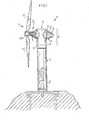
- a windmill park may comprise a series of identical windmills 1 embodying the invention, which windmills 1 may be of the horizontal shaft type and a hoisting implement adapted to travel along said windmills.
- Each windmill 1 (Fig.l) comprises a mill shaft 5 and a cabin 6 carried by the mill shaft 5.
- the cabin 6 comprises a stationary cabin part 7 and two cabin parts 8 and 9 mounted on the stationary cabin part 7.
- the stationary cabin part 7 has the shape of a hori-. zontal cylinder 10, which is connected with and welded to a cylindrical topmost mill.shaft part 11. By means of said mill shaft_part 11 and a rotary crown 12 the stationary cabin part 7 is rotatably arranged on a stationary mill shaft 13 of the mill shaft 5.
- the cabin part 8 (Fig.3), hereinafter termed rotor cabin part 8, comprises a number of mechanisms to wit: a rotor shaft 18, a gear wheel drive 19 and a blade setting mechanism 20.
- This rotor cabin part 8 comprises a cabinet 21 having a wall 22 fastened to the stationary cabin part 7, a free end 23 directed towards a mill rotor 26 and an intermediate, diverging jacket 24, a rotor bearing housing 25, in which a mill rotor 26 is journalled by means of its rotor shaft 18 and a gear wheel drive housing 27, in which the gear wheel drive 19 is journalled, which is driven by the rotor shaft 18.
- the cabin part 9, hereinafter termed generator scre ning hood 9, has the shape of a truncated cone and surrounds mechanism comprising a generator 28 journalled on the stationary cabin part 7.
- An intermediate shaft 32 arranged in the stationary cabin part 7 connects by means of disengageable couplings 33 and 34 and output shaft 31 of the gear wheel drive 19 with a shaft of the generator 28.
- the rotor cabin part 8 with the mechanisms 18, 19 a 20 arranged therein and the stationary cabin part 7 are detachably interconnected with the aid of fastening means forme by bolts 29.
- the generator screening hood 9 surrounding the generator 28 and the generator 28 journalled on the stationary cabin pa 7 by a sliding fit in a carrying frame 100 on the one hand and the stationary cabin part 7 on the other hand are-detachably interconnected by fastening means formed by bolts 42 for the generator screening hood 9 and by bolts 115 for the generator 28.
- a hoisting cord of the hoisting implement can be fastened to the tackling eyelets 39 or 111 in order to remove the rotor cabin part 8, the generator screening hood 9 or the generator 28 from the stationary cabin part 7.
- the bolts 29 fastening the rotor cabin part 8 to the stationary cabin part 7 can be manipulated from within the cabin 6 and are screwed through holes 101 in. a centering flange 1 02 of the stationary cabin part 7 into tapped holes 30 of the wall 22 of the rotor cabin part 8.
- the rotor cabin part 8 and the mechanisms 18, 19, 20 surrounded by the rotor cabin part 8 can be removed together by a single manipulation with the aid of the hoisting implement from the stationary cabin part 7, after in order of succession the hoisting cord of the hoisting implement is fastened to the eyelets 39 of the rotor cabin part 8, the coupling 33 is loosened from within the cabin. 6 and the bolts 29 fastening the rotor cabin part 8 to the stationary cabin part 7 are unscrewed.
- the bolts 42 fastening the generator screening hood 9 to the stationary cabin part 7 can be manipulated from- within the cabin.6 and are screwed through holes 103 in a flange 104 of the stationary cabin part 7 into tapped holes 105 of a flange 106 of the generator screening hood 9.
- the generator. screening hood 9 can be removed from the stationary cabin part. 7, after in order of succession the hoisting cord of the hoisting implement is fastened to the eyelet 39 of the generator screening hood 9 and the bolts 42 fastening the generator screening hood 9 to the stationary cabin part 6 are unscrewed from within the cabin 6.
- the bolts 115 fastening the generator 28 to the stationary cabin part 7 are screwed through holes 107 in a centering flange structure 117 of the carrying frame 100 of the stationary cabin part 7 into tapped holes 108 of a flange 109 of the generator 28.
- the generator 28 can be removed with the aid of the hoisting implement from the stationary cabin part. 7 after, in order of succession, the hoisting cord of the hoisting implement is fastened to the eyelet 111 of the generator housing 38 the coupling 34 is loosened from within the cabin 6, the bolts 115 are unscrewed from within the cabin 6 and the generator 28 is slipped out of the carrying frame 100 in which it is accomodated with sliding fit.
- the rotor cabin part 8 and the mechanisms 18, 19, 20 surrounded by the rotor cabin part 8 constitute an integral unit which is detachably connected on the one hand with the stationary cabin part 7 on the other hand with one another Furthermore the generator hood 9 and the mechanism 2& surrounded by the generator hood 9 are detachably connected each with the stationary cabin part 7 and with one another.
- the rotor cabin part 8 of the cabin 6 of the windmill 1 comprises the cabinet 21, the rotor bearing housing 25 and the gear wheel drive housing 27.
- the rotor bearing housing 25 and the gear wheel drive housing 27 are accomodated in the cabinet 21, the diverging jacket.24 of which forms a wall 24 of the gear wheel drive housing 27 (Fig. 3).
- the diverging jacket.24 of which forms a wall 24 of the gear wheel drive housing 27 (Fig. 3).
- In a longitudinal plane bounded by the rotor axis 41 are undetachably connected parts of the diverging jacket 24, parts of the gear wheel drive housing 27 and parts of the rotor bearing housing 27 and are associated with one and the same monolith .43..
- the cabinet 21, the rotor bearing housing 25 and the gear wheel drive housing 27 constitute an integral unit.
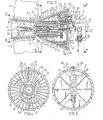
- This integral unit is divisible in the direction of the rotor axis 41 into two monolithicparts 44 and 45 (Figs. 4 and 5).
- the monolithic parts 44, 45 are fastened to one another by fastening means comprising bolts 46 and nuts 47.
- auxiliary mechanisms for example, a turning motor 49 and a lubricating oil pump 50 are coupled with the rotor shaft 18 by means of the gear wheel drive 19.
- A.frame 15 for the auxiliary mechanisms 49 and 50 is detachably fastened to the wall 22 of the cabinet 21 of the rotor cabin part.8.
- the lubricating oil pump 50 supplied through oil duct 52 the lubricating oil 57 to the bearings 53 to 56 the oil being collected below in the cabinet 21.
- the outer face 36 of the diverging jacket 24 is provided with cooling vanes 58 for cooling the lubricating oil 57 contained in the cabinet 21.
- the cooling vanes 58 provided on the outer face 36 of the diverging jacket 24 serve in addition as stiffening vanes.
- the cabin 6 is self-supporting and derives the require rigidity from its shape.
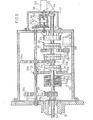
- the blade setting mechanism 20 for adjusting rotor blades 61 of the mill rotor 26, which is rotatably journalled by means of its rotor shaft 18 on the rotor cabin part 8 of the cabin 6 of the windmill 1 is passed through the hollow rotor shaft.
- the blade setting mechanism 20 comprises a rotation motor for example, an electric motor 63 fed from a source of energy 62 and setting means comprising a spindle shaft 64 coupling the electric motor 63 with the rotor blades 61.
- the spindle shaft 64 is journalled by means of a bearing 112 in the hollow rotor shaft and is rigidly connected at one end with the output shaft of a reducing gear box on the electric motor 63. At the other end the spindle shaft is in engagement by means of a worm 71 with a gland 68, which is displaceable in an axial direction in the hollow rotor shaft 18 and guarded against rotation and which is furthermore connected through a rod system 69 with the consoles 78 on the collar 59 of the rotor blades 61 rotatably journalled in the rotor hub 121. Between the spindle shaft 64 and the rotor shaft 18 is arranged an electro-magnetic coupling 65 and on the shaft 67 of the driving motor 63 an electro-magnetic brake 66.
- Setting of the rotor blades 16 occurs when the spindle shaft 64 has a speed of rotation differing from that of the rotor shaft in a manner such that, when the spindle shaft 64 rotates in the same direction more rapidly than the rotor shaft.18, the rotor blades 61 are adjusted from the vane position and, when the spindle shaft 64 rotates more slowly, adjustment takes place towards the vane position.
- the spindle shaft 64 is fixedly coupled with the rotor shaft 18 by means of the electro-magnetic coupling 65, whilst the electro-magnetic brake 66 is not operative and the electric motor 63 is not energized.
- the electro-magnetic coupling 65 as well as the electro-magnetic brake 66 are inoperative and the electric notor 63 is energized in order to attain the number of revolutions required for the adjustment.
- the electric motor 63 can be driven with at least two speeds, a high speed so that the spindle shaft 64 assumed a rotary speed equal to that of the rotor shaft 18 at the maximum permissible operative rotor speed and a low speed so that the spindle shaft 64 assumed a rotary speed equal to or lower than that of the rotor shaft 18 at the minimum operative rotor speed. Therefore, for causing a windmill 11 to attain the operative speed out of the rest position, in which tne rotor blades 61 are in the vane position, the electric motor 63 has to be driven first with a low speed and subsequently with a high speed in order to attain an operative rotor speed lying between minimum and maximum.
- the electri motor 63 In order to reduce the maxi mum operative speed to the minimum operative speed the electri motor 63 has to be driven with the low speed. If the windmill 1 after having reached the minimum operative speed has to be set in the rest position, the manipulations described hereinafter are carried out for putting the windmill out of operation in an emergency case.
- the spimle shaft 64 is coupled by means of a worm 71 with the gland 68, which is slidably journalled in the hollow rotor shaft 18 by means of guide rods 72 and is guarded against rotation with respect to the rotor shaft 18.
- the rotor shaft 18 is provided with an annular bumper 73, which is fastened by means of bolts 74 to the rotor shaft 18 and on which the guide rods are arranged.
- the gland 68 is coupled wit the rod system 69.
- the rod system 69 comprises rods 76, which are connected to the one hand by means of ball-and-socket joints with the gland 68 and on the other hand by means of ball-and socket joints 77 with consoles 78 (Fig. 6).
- the console.78 is fastened to a collar 59 of the rotor blade 61, which is rotatably journalled by means of a rotary crown 60 at the free end 42 of the rotor shaft 18.
- the electro-magnetic multiple disc clutch 65 comprises an annular electro-magnet 79 accommodated in an energization housing 122 and journalled by means of bearings 80 around a star wedge sleeve 81 (Fig. 7).
- the energization housing 122 is guarded against rotation with respect to the wall 22 of the rotor cabin part 8 and for this purpose the energization housing 122 has at least one recess 123 for a lug 124 fastened to the wall 22.
- the star wedge sleeve 81 is arranged around the rotor shaft 18 and guarded against rotation with respect to )the rotor shaft 18 by means of a key .
- the star wedge sleeve 81 On the star wedge sleeve 81 are arranged axially slidable lamellae 83 guarded against rotation relative to the star wedge sleeve 81 and extending in an radial direction.
- the lamellae 83 are surrounded by a star wedge housing 84, which is arranged on the spindle shaft 64 and guarded against rotation relative to the spindle shaft by means of a key 85.
- On the inner face 86 of the star wedge housing 84 On the inner face 86 of the star wedge housing 84 are arranged axially slidable lamellae 37 guarded against rotation relative to the star wedge housing 84 and extending in spaces between the lamellae 83 and the star wedge housing 84.
- the electric motor 63 and the electro-magnetic brake 66 acting on the shaft 67 of the electric motor 63 are fastened to a frame 89 by means of the reduction gearing housing 99 of the reduction gearing 70.
- the frame 89 is releasably connected with the built-on wall 22 of the cabinet 21 of the rotor cabin part 8.
- a control-system for actuating the blade setting mechanism 20 includes feelers 90 accessing the rotary speed of the rotor shaft 18 and beingconnected by fastening means 91, 92 with the wall 22 of the cabinet.21 of the rotor cabin part 8.
- the control-signals required for the blade setting mechanism originate from the control-system which will not be discussed herein.
- the.blades 61 are adjusted by means of the blade setting mechanism 20 towards and, respectively, away form the vane position.
- the electro-magnetic clutch 65 When the electric power is lacking due to disturbance, the electro-magnetic clutch 65 is released so that the spindle shaft 64 is disconnected from the rotor shaft 18, whilst the electro-magnetic brake 66 on the electric motor shaft 67 of the electric motor 63 is actuated so that the rotation of the spindle shaft 64, which is coupled by means of the reduction gearing 70 with the electric motor shaft 67, is slowed down relatively to the rotor shaft 18 and the rotor blades 61 are adjusted towards the vane position without using the electric motor 63 and the mill rotor 26 comes to a stand- still.
- the variant of the blade setting mechanism 20 shown in Fig. 8 is identical to the blade setting mechanism 20 of Fig. 3, the difference being that the spindle shaft 64 is coupled through a bevel gearing 93 with the rotor blades 61.
- the rotor cabin part 8 embodying the invention with which the cabinet 21 r the rotor bearing housing 25 and the gear wheel drive housing 27 constitute an integral unit, can be removed together with the mechanismsl8, 19, 20 surrounded by the rotor cabin part 8 as an unit from-the stationary cabin part. 7 of the cabin 6.
- the rotor cabin part 8 to be removed for maintenance or repair purposes can be replaced by a spare rotor cabin part 8, after which the maintenance and repair operations can be carried in a revision shop.
- Fig.9 shows a blade setting mechanism by which during the operation of the windmill in addition the blade setting angles can be varies for taking up the prescribed working position associated with a change of wind speed without such setting requiring an internal source of energy.
- Fig.9 shows quite schematically the drive of the spindle shaft 64 of the blade setting mechanism 20, in which the auxiliary shaft 130 is driven by the rotor shaft 18 by means of a pair of gear wheels 131 in a manner such that the auxiliary shaft 130 rotates with lower speed than the rotor shaft 18.
- the gear wheel_131a is rigidly secured .to the auxi--..- liary shaft 130.
- the gear.wheel 131b is rigidly secured to the part 132a of an electro-magnetic laminated clutch 132 and the spindle shaft 64 is fixedly connected with the other part 132b of the clutch 132.
- the housing 132c of the energizing coil is standing still.
- the auxiliary shaft 130 and the spindle shaft 64 are interconnected by means of the pairs of gear wheels 133, 134 and the clutches 135, 136.
- the driving means 133 to 136 for driving the spindle shaft 64 by the auxiliary shaft 130 are formed by two actuable clutches 135, 136, each of which is connected on the one hand by one clutch part 135b, 136b with the spindle shaft 64 and each of which is driven on the other hand through a coupling gear wheel 133b, 134b fastened to the other clutch part 135a, 136b with auxiliary shaft 130 gear wheels 133a, 134a, whilst the coupling gear wheels 133b, 134b of the two clutch parts 135a, 136a are larger and, respectively, smaller than the corresponding auxiliary shaft gear wheels 133a, 134a.
- the spindle shaft 64 can be brought into connection with the rotation motor 63, which may be provided with a reduction transmission box 139.
- the spindle shaft 64 is furthermore provided with a spring-energized, electro-magnetic brake 66.
- the mode of operation of the drive of the spindle shaft 64 with the aid of the auxiliary shaft 130 is as follows: At the energization of the clutches 132, 135, 136 the spindle shaft 64 is driven by the rotor shaft 18 itself or, respectively, one of the pairs of gear wheels 133, 134. When the clutch 139 is energized, the spindle shaft 64 is driven by the rotation motor 63 through the pair of gear wheels 137. When only the brake 66 is energized, setting to the vane position occurs in emergency cases.
- the transmission ration of the pair of gear wheels 13 in conjunction with the pair of gear wheels 133 and the pair of gear wheels 134 respectively is such that upon energizatic of the respective clutches 135 and 136 the spindle shaft 64 rotates with lower and, respectively higher speed than the rotor shaft 18, that is to say, in both cases in the same ratio.
- the differential mechanism 140 comprises two differential gear wheels 141 and 142.
- the gear wheel 141 is driven via a gear wheel transmission 143 by the auxiliary shaft 130 and the.
- gear wheel 142 is driven through a gear wheel transmission 144 by the spindle shaft 64.
- the transmission ratios of the gear wheel transmission 143 and 144 are chosen so that the transmission ratios on the one hand between the spindle shaft 64 and the differential gear wheels 142 and on the other hand between the rotor shaft 18 and the differential gear wheel 142 are the same, whilst the gear wheels 141 and 142 are driven in opposite senses.
- the differential element-145 will not rotate.
- the element 145 will turn about the shaft 146. and occupy a different position.
- the position of this element 145 relative to the housing 147 is proportional to the blade setting angle and be assessed with the aid of a sensor 148.
Landscapes
- Engineering & Computer Science (AREA)
- Physics & Mathematics (AREA)
- Fluid Mechanics (AREA)
- Life Sciences & Earth Sciences (AREA)
- Sustainable Development (AREA)
- Sustainable Energy (AREA)
- Chemical & Material Sciences (AREA)
- Combustion & Propulsion (AREA)
- Mechanical Engineering (AREA)
- General Engineering & Computer Science (AREA)
- Wind Motors (AREA)
Applications Claiming Priority (4)
| Application Number | Priority Date | Filing Date | Title |
|---|---|---|---|
| NL8201281 | 1982-03-26 | ||
| NL8201281A NL8201281A (nl) | 1982-03-26 | 1982-03-26 | Bladverstelmechanisme voor de rotorbladen van een windmolen. |
| NL8204845 | 1982-12-15 | ||
| NL8204845A NL8204845A (nl) | 1982-03-26 | 1982-12-15 | Bladverstelmechanisme voor de rotorbladen van een windmolen. |
Publications (3)
| Publication Number | Publication Date |
|---|---|
| EP0094106A2 true EP0094106A2 (de) | 1983-11-16 |
| EP0094106A3 EP0094106A3 (en) | 1984-01-11 |
| EP0094106B1 EP0094106B1 (de) | 1986-10-15 |
Family
ID=26645766
Family Applications (1)
| Application Number | Title | Priority Date | Filing Date |
|---|---|---|---|
| EP83200410A Expired EP0094106B1 (de) | 1982-03-26 | 1983-03-23 | Flügelblattverstellvorrichtung für ein Windrad |
Country Status (3)
| Country | Link |
|---|---|
| EP (1) | EP0094106B1 (de) |
| DE (1) | DE3366999D1 (de) |
| NL (1) | NL8204845A (de) |
Cited By (15)
| Publication number | Priority date | Publication date | Assignee | Title |
|---|---|---|---|---|
| GB2159584A (en) * | 1984-05-21 | 1985-12-04 | Taylor Woodrow Const Ltd | Pitch control apparatus |
| WO1991019916A1 (en) * | 1990-06-09 | 1991-12-26 | Hicks Transmissions Limited | Epicyclic gear train |
| DE4221783A1 (de) * | 1992-07-03 | 1994-01-05 | Klinger Friedrich Prof Dr Ing | Vorrichtung zur Verstellung von Rotorblättern |
| DE19644705A1 (de) * | 1996-10-28 | 1998-04-30 | Preussag Ag | Vorrichtung zur Verstellung von Rotorblättern |
| ES2140301A2 (es) * | 1997-05-20 | 2000-02-16 | Torres Martinez M | Aerogenerador. |
| WO2000009885A1 (en) * | 1998-08-13 | 2000-02-24 | Neg Micon A/S | A method and a device for adjusting the pitch and stopping the rotation of the blades of a wind turbine |
| ES2144363A1 (es) * | 1998-03-26 | 2000-06-01 | Torres Martinez M | Perfeccionamientos en los aerogeneradores productores de electricidad. |
| WO2000061942A1 (en) * | 1999-04-14 | 2000-10-19 | Neg Micon A/S | Device for adjusting the pitch of the blades of a wind turbine and a method for stopping the rotation of the main shaft |
| WO2006096895A1 (de) * | 2005-03-18 | 2006-09-21 | Windtec Consulting Gmbh | Verfahren und vorrichtung zum abbremsen des rotors einer windkraftanlage |
| WO2006105901A1 (de) * | 2005-04-08 | 2006-10-12 | Ssb-Antriebstechnik Gmbh & Co. Kg | Windenergieanlage |
| US20080207389A1 (en) * | 2007-02-22 | 2008-08-28 | Jurgen Fahrenbach | Drive hub unit for a wind power generator |
| EP2372151A1 (de) | 2010-03-29 | 2011-10-05 | Ecotecnia Energias Renovables S.L. | Windturbine |
| WO2011088925A3 (de) * | 2010-01-23 | 2012-02-23 | Schaeffler Technologies Gmbh & Co. Kg | Windenergieanlage mit einem oder mehreren rotorblättern |
| GB2492462A (en) * | 2011-06-27 | 2013-01-02 | Tidalstream Ltd | Variable pitch rotor of underwater turbine |
| CN103452765A (zh) * | 2013-09-10 | 2013-12-18 | 焦作瑞塞尔盘式制动器有限公司 | 一种风力发电机组 |
Citations (7)
| Publication number | Priority date | Publication date | Assignee | Title |
|---|---|---|---|---|
| BE445358A (de) * | ||||
| DE695463C (de) * | 1936-12-19 | 1940-08-29 | Adolf Jolk | Selbsttaetige Regelvorrichtung fuer Windraeder |
| US2370135A (en) * | 1941-09-25 | 1945-02-27 | Engineering & Res Corp | Variable pitch propeller |
| FR1109809A (fr) * | 1954-07-02 | 1956-02-02 | Const Aero Navales | Dispositif pour le contrôle de l'incidence des pales, notamment d'une roue éolienne |
| FR2291378A1 (fr) * | 1974-11-14 | 1976-06-11 | Carre Jean | Aerogenerateur a rotor perfectionne |
| FR2313576A1 (fr) * | 1975-06-06 | 1976-12-31 | Buys Victor | Machine eolienne a vitesse de rotation constante |
| WO1983000195A1 (en) * | 1981-07-13 | 1983-01-20 | Allan Chertok | Windpower system |
-
1982
- 1982-12-15 NL NL8204845A patent/NL8204845A/nl not_active Application Discontinuation
-
1983
- 1983-03-23 EP EP83200410A patent/EP0094106B1/de not_active Expired
- 1983-03-23 DE DE8383200410T patent/DE3366999D1/de not_active Expired
Patent Citations (7)
| Publication number | Priority date | Publication date | Assignee | Title |
|---|---|---|---|---|
| BE445358A (de) * | ||||
| DE695463C (de) * | 1936-12-19 | 1940-08-29 | Adolf Jolk | Selbsttaetige Regelvorrichtung fuer Windraeder |
| US2370135A (en) * | 1941-09-25 | 1945-02-27 | Engineering & Res Corp | Variable pitch propeller |
| FR1109809A (fr) * | 1954-07-02 | 1956-02-02 | Const Aero Navales | Dispositif pour le contrôle de l'incidence des pales, notamment d'une roue éolienne |
| FR2291378A1 (fr) * | 1974-11-14 | 1976-06-11 | Carre Jean | Aerogenerateur a rotor perfectionne |
| FR2313576A1 (fr) * | 1975-06-06 | 1976-12-31 | Buys Victor | Machine eolienne a vitesse de rotation constante |
| WO1983000195A1 (en) * | 1981-07-13 | 1983-01-20 | Allan Chertok | Windpower system |
Cited By (20)
| Publication number | Priority date | Publication date | Assignee | Title |
|---|---|---|---|---|
| GB2159584A (en) * | 1984-05-21 | 1985-12-04 | Taylor Woodrow Const Ltd | Pitch control apparatus |
| WO1991019916A1 (en) * | 1990-06-09 | 1991-12-26 | Hicks Transmissions Limited | Epicyclic gear train |
| DE4221783A1 (de) * | 1992-07-03 | 1994-01-05 | Klinger Friedrich Prof Dr Ing | Vorrichtung zur Verstellung von Rotorblättern |
| DE19644705A1 (de) * | 1996-10-28 | 1998-04-30 | Preussag Ag | Vorrichtung zur Verstellung von Rotorblättern |
| ES2140301A2 (es) * | 1997-05-20 | 2000-02-16 | Torres Martinez M | Aerogenerador. |
| ES2144363A1 (es) * | 1998-03-26 | 2000-06-01 | Torres Martinez M | Perfeccionamientos en los aerogeneradores productores de electricidad. |
| WO2000009885A1 (en) * | 1998-08-13 | 2000-02-24 | Neg Micon A/S | A method and a device for adjusting the pitch and stopping the rotation of the blades of a wind turbine |
| US6609889B1 (en) | 1998-08-13 | 2003-08-26 | Neg Micon A/S | Method and a device for adjusting the pitch and stopping the rotation of the blades of a wind turbine |
| WO2000061942A1 (en) * | 1999-04-14 | 2000-10-19 | Neg Micon A/S | Device for adjusting the pitch of the blades of a wind turbine and a method for stopping the rotation of the main shaft |
| EP1990538A3 (de) * | 2005-03-18 | 2009-11-11 | AMSC Windtec GmbH | Vorrichtung zum Abbremsen eines Rotors einer Windkraftanlage |
| WO2006096895A1 (de) * | 2005-03-18 | 2006-09-21 | Windtec Consulting Gmbh | Verfahren und vorrichtung zum abbremsen des rotors einer windkraftanlage |
| WO2006105901A1 (de) * | 2005-04-08 | 2006-10-12 | Ssb-Antriebstechnik Gmbh & Co. Kg | Windenergieanlage |
| US20080207389A1 (en) * | 2007-02-22 | 2008-08-28 | Jurgen Fahrenbach | Drive hub unit for a wind power generator |
| EP1961958A3 (de) * | 2007-02-22 | 2012-11-28 | Schuler Pressen GmbH & Co. KG | Getriebe-Nabeneinheint für eine Windkraftanlage |
| WO2011088925A3 (de) * | 2010-01-23 | 2012-02-23 | Schaeffler Technologies Gmbh & Co. Kg | Windenergieanlage mit einem oder mehreren rotorblättern |
| EP2372151A1 (de) | 2010-03-29 | 2011-10-05 | Ecotecnia Energias Renovables S.L. | Windturbine |
| US8662850B2 (en) | 2010-03-29 | 2014-03-04 | Alstom Wind, S.L.U. | Wind turbine |
| GB2492462A (en) * | 2011-06-27 | 2013-01-02 | Tidalstream Ltd | Variable pitch rotor of underwater turbine |
| CN103452765A (zh) * | 2013-09-10 | 2013-12-18 | 焦作瑞塞尔盘式制动器有限公司 | 一种风力发电机组 |
| CN103452765B (zh) * | 2013-09-10 | 2016-10-05 | 焦作瑞塞尔盘式制动器有限公司 | 一种风力发电机组 |
Also Published As
| Publication number | Publication date |
|---|---|
| NL8204845A (nl) | 1983-10-17 |
| EP0094106B1 (de) | 1986-10-15 |
| EP0094106A3 (en) | 1984-01-11 |
| DE3366999D1 (en) | 1986-11-20 |
Similar Documents
| Publication | Publication Date | Title |
|---|---|---|
| US4527072A (en) | Divisible cabin for a windmill | |
| EP0094106B1 (de) | Flügelblattverstellvorrichtung für ein Windrad | |
| RU2234439C2 (ru) | Приводная система гребного винта надводного судна и способ обеспечения движения и управления по курсу | |
| US5174716A (en) | Pitch change mechanism | |
| US6232673B1 (en) | Windmill | |
| US4750862A (en) | Modular propeller blade pitch actuation system | |
| US6925694B2 (en) | Tool turret | |
| US4676459A (en) | Double propeller for propelling aircraft | |
| GB2035482A (en) | Infinitely variable friction drive | |
| US4223770A (en) | Shaft drive alternately for both directions of rotation | |
| US4820209A (en) | Torque converter marine transmission with variable power output | |
| FI95451B (fi) | Potkurikäyttöjärjestelmä | |
| US5588931A (en) | Planetary reducer and wheel bearing unit | |
| JPS5828061B2 (ja) | 切換衝撃緩衝用切換装置 | |
| US5441388A (en) | Ship drive with two counterturning propellers | |
| EP0651713B1 (de) | Antriebssystem eines rotors mit veränderlichem durchmesser | |
| EP0603291B1 (de) | Getriebe für Bootsmotoren | |
| EP0093461A1 (de) | Gondelteil einer teilbaren Gondel für Windenergieanlage | |
| EP2944807B1 (de) | Staudruckturbine | |
| JPS60157998A (ja) | 船舶用駆動装置 | |
| US4170905A (en) | Propulsion plant including a gas turbine and a reduction gear | |
| CN213895023U (zh) | 一种直驱双动力钻井绞车 | |
| JPH05246385A (ja) | ウォータジェット推進機の軸受冷却装置 | |
| JPS58131448A (ja) | 伝動装置 | |
| US4112866A (en) | Propeller mechanism having removable propeller shaft |
Legal Events
| Date | Code | Title | Description |
|---|---|---|---|
| PUAI | Public reference made under article 153(3) epc to a published international application that has entered the european phase |
Free format text: ORIGINAL CODE: 0009012 |
|
| PUAL | Search report despatched |
Free format text: ORIGINAL CODE: 0009013 |
|
| AK | Designated contracting states |
Designated state(s): BE DE FR GB IT NL SE |
|
| AK | Designated contracting states |
Designated state(s): BE DE FR GB IT NL SE |
|
| 17P | Request for examination filed |
Effective date: 19840711 |
|
| RAP1 | Party data changed (applicant data changed or rights of an application transferred) |
Owner name: FDO TECHNISCHE ADVISEURS B.V. |
|
| GRAA | (expected) grant |
Free format text: ORIGINAL CODE: 0009210 |
|
| ITF | It: translation for a ep patent filed | ||
| AK | Designated contracting states |
Kind code of ref document: B1 Designated state(s): BE DE FR GB IT NL SE |
|
| REF | Corresponds to: |
Ref document number: 3366999 Country of ref document: DE Date of ref document: 19861120 |
|
| ET | Fr: translation filed | ||
| PLBE | No opposition filed within time limit |
Free format text: ORIGINAL CODE: 0009261 |
|
| STAA | Information on the status of an ep patent application or granted ep patent |
Free format text: STATUS: NO OPPOSITION FILED WITHIN TIME LIMIT |
|
| 26N | No opposition filed | ||
| PGFP | Annual fee paid to national office [announced via postgrant information from national office to epo] |
Ref country code: GB Payment date: 19910227 Year of fee payment: 9 Ref country code: BE Payment date: 19910227 Year of fee payment: 9 |
|
| PGFP | Annual fee paid to national office [announced via postgrant information from national office to epo] |
Ref country code: SE Payment date: 19910228 Year of fee payment: 9 |
|
| PGFP | Annual fee paid to national office [announced via postgrant information from national office to epo] |
Ref country code: FR Payment date: 19910319 Year of fee payment: 9 |
|
| PGFP | Annual fee paid to national office [announced via postgrant information from national office to epo] |
Ref country code: DE Payment date: 19910328 Year of fee payment: 9 |
|
| ITTA | It: last paid annual fee | ||
| PGFP | Annual fee paid to national office [announced via postgrant information from national office to epo] |
Ref country code: NL Payment date: 19910331 Year of fee payment: 9 |
|
| PG25 | Lapsed in a contracting state [announced via postgrant information from national office to epo] |
Ref country code: GB Effective date: 19920323 |
|
| PG25 | Lapsed in a contracting state [announced via postgrant information from national office to epo] |
Ref country code: SE Effective date: 19920324 |
|
| PG25 | Lapsed in a contracting state [announced via postgrant information from national office to epo] |
Ref country code: BE Effective date: 19920331 |
|
| BERE | Be: lapsed |
Owner name: FDO TECHNISCHE ADVISEURS B.V. Effective date: 19920331 |
|
| PG25 | Lapsed in a contracting state [announced via postgrant information from national office to epo] |
Ref country code: NL Effective date: 19921001 |
|
| NLV4 | Nl: lapsed or anulled due to non-payment of the annual fee | ||
| GBPC | Gb: european patent ceased through non-payment of renewal fee | ||
| PG25 | Lapsed in a contracting state [announced via postgrant information from national office to epo] |
Ref country code: FR Effective date: 19921130 |
|
| PG25 | Lapsed in a contracting state [announced via postgrant information from national office to epo] |
Ref country code: DE Effective date: 19921201 |
|
| REG | Reference to a national code |
Ref country code: FR Ref legal event code: ST |
|
| EUG | Se: european patent has lapsed |
Ref document number: 83200410.5 Effective date: 19921005 |