EP0093674A1 - Kompressor - Google Patents
Kompressor Download PDFInfo
- Publication number
- EP0093674A1 EP0093674A1 EP83400888A EP83400888A EP0093674A1 EP 0093674 A1 EP0093674 A1 EP 0093674A1 EP 83400888 A EP83400888 A EP 83400888A EP 83400888 A EP83400888 A EP 83400888A EP 0093674 A1 EP0093674 A1 EP 0093674A1
- Authority
- EP
- European Patent Office
- Prior art keywords
- inlet
- assembly
- plate
- housing
- reeds
- Prior art date
- Legal status (The legal status is an assumption and is not a legal conclusion. Google has not performed a legal analysis and makes no representation as to the accuracy of the status listed.)
- Withdrawn
Links
Images
Classifications
-
- F—MECHANICAL ENGINEERING; LIGHTING; HEATING; WEAPONS; BLASTING
- F04—POSITIVE - DISPLACEMENT MACHINES FOR LIQUIDS; PUMPS FOR LIQUIDS OR ELASTIC FLUIDS
- F04B—POSITIVE-DISPLACEMENT MACHINES FOR LIQUIDS; PUMPS
- F04B39/00—Component parts, details, or accessories, of pumps or pumping systems specially adapted for elastic fluids, not otherwise provided for in, or of interest apart from, groups F04B25/00 - F04B37/00
- F04B39/10—Adaptations or arrangements of distribution members
- F04B39/1073—Adaptations or arrangements of distribution members the members being reed valves
Definitions
- the present invention relates to a compressor with reciprocating pistons, which, among many other possible applications, can be used as an air compressor on heavy automotive vehicles.
- Such a compressor usually comprises a housing with bores formed therein, pistons reciprocably mounted in said bores and defining therewith operational chambers, a head assembly provided with inlet and outlet ports, and a valve assembly interposed between the housing and the head assembly for allowing fluid to flow from said inlet port to said operational chambers in response to movement of said pistons in one direction and for allowing compressed fluid to flow from said operational chambers to said outlet port in response to movement of said pistons in another direction.
- an object of the present invention to extend the field of applications of such compressors by substantially reducing the manufacturing cost of their valve assemblies, while still keeping them liable in operation and easy to disassemble for maintenance or replacement.
- valve assembly comprises a plate having inlet and outlet openings for connecting the operational chambers with the inlet and outlet ports, a reed assembly having a metal substrate with a gasket material printed thereon, said metal substrate having a plurality of reeds formed therein which cooperate with said plate and with the head assembly for controlling fluid flow through said inlet and outlet openings, and fastener means for aligning and holding said reed assembly, said plate and said head assembly with respect to the compressor housing.
- Such a reed assembly is easy and little expensive to manufacture, while the fastener means (bolts, for instance) provide for accurate alignment of the various reeds over the inlet and outlet openings formed in the plate, and therefore, for a liable operation.
- the valve assembly further comprises a plunger.or ' piston having a face connected to receive the fluid pressure from stored compressed fluid and at least one projection that extends toward the reed assembly, and resilient means for urging said piston away from said reed assembly, said fluid pressure of the stored compressed fluid acting on said piston face and overcoming said resilient means to allow said piston to move and engage the inlet reeds in a manner such that the operational chambers are continually connected to the inlet port. Thereafter the work required to move the pistons in their associated bores is substantially reduced while the transmission of compressed fluid to the storage container is terminatea.
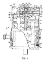
- the compressor 10 shown in Figure 1 has a housing 12 with a chamber 14 therein. Cylindrical members or sleeves 16 and 18 are aligned over openings 20 and 22 in housing 12.
- a crankshaft 24 has a first end 26 journalled in a bearing 28 retained in an end plate 30 of housing 12 and a second end 34 that extends through an end plate 32.
- a second bearing 36 retained in end plate 32 allows the crankshaft 24 to rotate in chamber 14 whenever a rotary torque is applied to end 34.
- the cylindrical members 16 and 18 could be replaced by conventional cylindrical bores formed integrally with the housing.
- Pistons 38 and 40 which are located in cylindrical members 16 and 18, respectively, are connected to crankshaft 24 by rods 42 and 44. Pistons 38 and 40 are located at 180° from each other on crankshaft 24 so that when one piston is at the top of its stroke the other piston is at the bottom of its stroke.
- a gasket 48 is located between ends 50 and 52 of cylindrical members 16 and 18 and a valve plate 54.
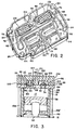
- Valve plate 54 which is best seen in.Figure 2 has inlet openings 56 and 58 and outlet openings 72 and 74 for one chamber -17 and inlet openings 60 and 62 and outlet openings 76 and 78 for another chamber 19.
- Valve plate 54 is flat with the exception of sloping and countoured surfaces 64 and 66 located ajdacent to inlet openings 56, 58 and 60, 62.
- the contoured surfaces 64 and 66 slope from apexes 68 and 70 toward points or stops 80 and 82.
- a flat stamped reed valve 84 has a metal substrate with peripheral surface 86 that matches the outline of valve plate 54 and inlet flaps or reeds 88 and 90 and outlet flaps or reeds 92 and 94 that are integrally formed therewith.
- a gasket material 95 is printed on the metal substrate that makes up the reed valve 84.
- a retainer 96 attached to valve plate 54 by bolts 98 and 100 has projections or arms 102 and 104 that extend over the outlet flaps or reeds 92 and 94.
- a head 106 positioned over reed valve 84 has an entrance port 108 that connects with a passage 110 and a chamber 112.
- the limits of chamber 112 are defined by the engagement of sealing surfaces 114, 115, 117, 119 and 121 on reed valve 84 with head 106.
- inlet flap 88 extends past seat 116 that surrounds opening 118.
- inlet flap or reed 90 extends, past seat 120 which surrounds opening 122 to control communication of fluid from chamber 112 into chamber 19.
- Head 106 has a bore 124 located therein which is connected to chamber 112.
- An unloader mechanism 123 which includes a piston 126 is located in bore 124. Piston cooperates with head 106 to define a chamber 128 in bore 124.
- a passage 125 is connected to a conventional governor control that communicates a pressure signal to chamber 128 when the pressure level in a storage container reaches a predetermined level.
- a seal 130 on piston 126 prevents communication between chambers 128 and 112.
- a spring 132 located between the bottom 134 of bore 124 and a retainer 136 and positioned with a boss 127 on the end of piston 126 urges end 138 against a stop 140.
- Retainer 136 has first and second projections 142 and 144 that extend through slots or holes 146 and 148 to a position over flaps or reeds 88 and 90.
- head 106 has a passage 150, see Figure 3, with a port 152 that is connected to the storage container. Head 106 engages gasket material 154 printed on the metal substrate of reed valve 84 to assure that passage 150 is separated from chamber 112 and the surrounding environment.
- Nuts 156, 156'....156 attach head 106 to housing 12.
- Head bolts 158, 158', 158" attach head 106 to housing 12.
- Head bolts 158, 158', 158"....158 N project from housing 12 and align valve plate 54, reed valve 84 and head 106 in a manner such that the inlet flaps or reeds 88 and 90 and outlet flaps or reeds 92 and 94 are over the openings into and out of the chambers 17 and 19.
- crankshaft 24 Rotary input applied to crankshaft 24 through end 34 causes pistons 38 and 40 to move in chambers 17 and 19. Pistons 38 and 40 are connected to crankshaft 24 such that when piston 38 is at the bottom of its stroke, piston 40 is at the top of its stroke and vice versa.
- piston 40 moves on the up or compression stroke to force air from chamber 19 through openings 76 and 78 into passage 150.
- flap 90 engages seat 120 to prevent air or fluid from being communicated from chamber 19 into chamber 112 while flap 94 moves away from valve plate 54 to allow free communication from chamber 19 to passage 150 through openings 76 and 78.
- pistons 38 and 40 When a half cycle of operation is completed, pistons 38 and 40 reverse with piston 40 on its down stroke and piston 38 on its up stroke.
- contour surfaces 64 and 66 which support the flaps or reeds 88 and 90 on the intake of air into chambers 17 and 19, reduce flexing of the hinge of the integrally formed reeds. This should add to the life of the valve arrangement 84. Should the valve arrangement 84 ever need to be replaced, all that is necessary is the removal of head nuts 156, 156'....156 and head 106. Thereafter, the retainer 96 and the valve arrangement 84 are removed. The retainer 96 is attached to a new valve arrangement 84 which is placed on bolts 158, 158'....158 N . These head bolts align the inlet flaps 88 and 90 and outlet flaps 92 and 94 over the openings in valve plate 54. Thereafter, head 106 is placed on bolts 158, 158'....158 N and nuts 156, 156'....156 N attached to complete the replacement of the valve arrangement 84.
Landscapes
- Engineering & Computer Science (AREA)
- Mechanical Engineering (AREA)
- General Engineering & Computer Science (AREA)
- Compressor (AREA)
- Check Valves (AREA)
Applications Claiming Priority (2)
| Application Number | Priority Date | Filing Date | Title |
|---|---|---|---|
| US37505482A | 1982-05-05 | 1982-05-05 | |
| US375054 | 1989-07-03 |
Publications (1)
| Publication Number | Publication Date |
|---|---|
| EP0093674A1 true EP0093674A1 (de) | 1983-11-09 |
Family
ID=23479308
Family Applications (1)
| Application Number | Title | Priority Date | Filing Date |
|---|---|---|---|
| EP83400888A Withdrawn EP0093674A1 (de) | 1982-05-05 | 1983-05-03 | Kompressor |
Country Status (4)
| Country | Link |
|---|---|
| EP (1) | EP0093674A1 (de) |
| JP (1) | JPS58206891A (de) |
| AU (1) | AU1417183A (de) |
| ES (1) | ES8404020A1 (de) |
Cited By (10)
| Publication number | Priority date | Publication date | Assignee | Title |
|---|---|---|---|---|
| US4721443A (en) * | 1987-03-16 | 1988-01-26 | Tecumseh Products Company | Discharge valve retainer for a compressor |
| EP0521730A2 (de) * | 1991-07-03 | 1993-01-07 | Sanden Corporation | Mehrzylinder-Verdichter |
| US5571000A (en) * | 1994-07-07 | 1996-11-05 | Shurflo Pump Manufacturing Co. | Booster pump with bypass valve integrally formed in gasket |
| WO1997016643A2 (en) * | 1995-11-01 | 1997-05-09 | Shurflo Pump Manufacturing Co. | Piston pump |
| US5791882A (en) * | 1996-04-25 | 1998-08-11 | Shurflo Pump Manufacturing Co | High efficiency diaphragm pump |
| US5800136A (en) * | 1997-02-28 | 1998-09-01 | Shurflo Pump Manufacturing Co. | Pump with bypass valve |
| US6048183A (en) * | 1998-02-06 | 2000-04-11 | Shurflo Pump Manufacturing Co. | Diaphragm pump with modified valves |
| US6623245B2 (en) | 2001-11-26 | 2003-09-23 | Shurflo Pump Manufacturing Company, Inc. | Pump and pump control circuit apparatus and method |
| US6715994B2 (en) | 2001-11-12 | 2004-04-06 | Shurflo Pump Manufacturing Co., Inc. | Bilge pump |
| WO2016028540A1 (en) * | 2014-08-19 | 2016-02-25 | Bendix Commercial Vehicle Systems Llc | Compressor head and gasket for same |
Citations (5)
| Publication number | Priority date | Publication date | Assignee | Title |
|---|---|---|---|---|
| US1633772A (en) * | 1921-03-18 | 1927-06-28 | Sullivan Machinery Co | Valve mechanism |
| US1986831A (en) * | 1932-03-19 | 1935-01-08 | Ingersoll Rand Co | Valve mechanism |
| GB619922A (en) * | 1946-12-22 | 1949-03-16 | Laycock Engineering Company Lt | Improvements in or relating to valve mechanism |
| GB1246256A (en) * | 1969-02-10 | 1971-09-15 | Hoerbiger Ventilwerke Ag | A valve set for a reciprocating piston-type compressor |
| DE2357578A1 (de) * | 1973-11-19 | 1975-05-22 | Billstein Spezialfab Wilhelm | Regelbare zungenventileinrichtung fuer kolbenverdichter |
-
1983
- 1983-05-03 AU AU14171/83A patent/AU1417183A/en not_active Abandoned
- 1983-05-03 EP EP83400888A patent/EP0093674A1/de not_active Withdrawn
- 1983-05-04 JP JP7764683A patent/JPS58206891A/ja active Pending
- 1983-05-04 ES ES522091A patent/ES8404020A1/es not_active Expired
Patent Citations (5)
| Publication number | Priority date | Publication date | Assignee | Title |
|---|---|---|---|---|
| US1633772A (en) * | 1921-03-18 | 1927-06-28 | Sullivan Machinery Co | Valve mechanism |
| US1986831A (en) * | 1932-03-19 | 1935-01-08 | Ingersoll Rand Co | Valve mechanism |
| GB619922A (en) * | 1946-12-22 | 1949-03-16 | Laycock Engineering Company Lt | Improvements in or relating to valve mechanism |
| GB1246256A (en) * | 1969-02-10 | 1971-09-15 | Hoerbiger Ventilwerke Ag | A valve set for a reciprocating piston-type compressor |
| DE2357578A1 (de) * | 1973-11-19 | 1975-05-22 | Billstein Spezialfab Wilhelm | Regelbare zungenventileinrichtung fuer kolbenverdichter |
Cited By (14)
| Publication number | Priority date | Publication date | Assignee | Title |
|---|---|---|---|---|
| US4721443A (en) * | 1987-03-16 | 1988-01-26 | Tecumseh Products Company | Discharge valve retainer for a compressor |
| EP0284653A1 (de) * | 1987-03-16 | 1988-10-05 | Tecumseh Products Company | Druckventilhubbegrenzer eines Verdichters |
| EP0521730A2 (de) * | 1991-07-03 | 1993-01-07 | Sanden Corporation | Mehrzylinder-Verdichter |
| EP0521730A3 (en) * | 1991-07-03 | 1993-10-13 | Sanden Corporation | Multicylinder compressor |
| US5571000A (en) * | 1994-07-07 | 1996-11-05 | Shurflo Pump Manufacturing Co. | Booster pump with bypass valve integrally formed in gasket |
| WO1997016643A3 (en) * | 1995-11-01 | 1997-09-12 | Shurflo Pump Mfg Co | Piston pump |
| WO1997016643A2 (en) * | 1995-11-01 | 1997-05-09 | Shurflo Pump Manufacturing Co. | Piston pump |
| US5791882A (en) * | 1996-04-25 | 1998-08-11 | Shurflo Pump Manufacturing Co | High efficiency diaphragm pump |
| US5800136A (en) * | 1997-02-28 | 1998-09-01 | Shurflo Pump Manufacturing Co. | Pump with bypass valve |
| US6048183A (en) * | 1998-02-06 | 2000-04-11 | Shurflo Pump Manufacturing Co. | Diaphragm pump with modified valves |
| US6715994B2 (en) | 2001-11-12 | 2004-04-06 | Shurflo Pump Manufacturing Co., Inc. | Bilge pump |
| US7806664B2 (en) | 2001-11-12 | 2010-10-05 | Shurflo, Llc | Bilge pump |
| US6623245B2 (en) | 2001-11-26 | 2003-09-23 | Shurflo Pump Manufacturing Company, Inc. | Pump and pump control circuit apparatus and method |
| WO2016028540A1 (en) * | 2014-08-19 | 2016-02-25 | Bendix Commercial Vehicle Systems Llc | Compressor head and gasket for same |
Also Published As
| Publication number | Publication date |
|---|---|
| JPS58206891A (ja) | 1983-12-02 |
| AU1417183A (en) | 1983-11-10 |
| ES522091A0 (es) | 1984-04-01 |
| ES8404020A1 (es) | 1984-04-01 |
Similar Documents
| Publication | Publication Date | Title |
|---|---|---|
| USRE36274E (en) | Method of manufacturing valve system for capacity control of a screw compressor | |
| EP1609984B1 (de) | Brennstoffeinspritzpumpe | |
| US5147190A (en) | Increased efficiency valve system for a fluid pumping assembly | |
| EP0630444B1 (de) | Pumpe und membran | |
| GB2204110A (en) | Compressor discharge valve assembly | |
| EP0093674A1 (de) | Kompressor | |
| EP0280264A2 (de) | Mehrstufen-Vakuumpumpe | |
| US4437490A (en) | Reed valve assembly | |
| US5022832A (en) | Ring valve type air compressor | |
| US5607287A (en) | Reciprocating piston type compressor with an improved discharge valve mechanism | |
| US6053713A (en) | Gas compressors | |
| KR20060052494A (ko) | 모듈식 사판 압축기 | |
| US4693674A (en) | Cylinder head for refrigerant compressor | |
| US20220186720A1 (en) | Compressor valve assembly | |
| US20050047928A1 (en) | Pump valve assembly | |
| EP0284653B1 (de) | Druckventilhubbegrenzer eines Verdichters | |
| GB2037898A (en) | Reciprocating piston compressors | |
| US4610606A (en) | Gas refrigerant compressor including ported walls and a piston of unitary construction having a domed top | |
| US3791776A (en) | Reciprocating cylinder type compressor having unloading means | |
| US4058138A (en) | Straightway valve | |
| US6098519A (en) | Fuel pump | |
| GB2165893A (en) | Unloading twin cylinder compressor | |
| US3936236A (en) | Compressor intake valve and control means | |
| US2865557A (en) | Compressor unloader | |
| EP0942171A2 (de) | Doppelmembranpumpe |
Legal Events
| Date | Code | Title | Description |
|---|---|---|---|
| PUAI | Public reference made under article 153(3) epc to a published international application that has entered the european phase |
Free format text: ORIGINAL CODE: 0009012 |
|
| 17P | Request for examination filed |
Effective date: 19830524 |
|
| AK | Designated contracting states |
Designated state(s): DE FR GB IT SE |
|
| STAA | Information on the status of an ep patent application or granted ep patent |
Free format text: STATUS: THE APPLICATION IS DEEMED TO BE WITHDRAWN |
|
| 18D | Application deemed to be withdrawn |
Effective date: 19840510 |
|
| RIN1 | Information on inventor provided before grant (corrected) |
Inventor name: REISINGER, PAUL G. |