EP0093592A2 - Apparatus for the inspection of syringes - Google Patents
Apparatus for the inspection of syringes Download PDFInfo
- Publication number
- EP0093592A2 EP0093592A2 EP83302432A EP83302432A EP0093592A2 EP 0093592 A2 EP0093592 A2 EP 0093592A2 EP 83302432 A EP83302432 A EP 83302432A EP 83302432 A EP83302432 A EP 83302432A EP 0093592 A2 EP0093592 A2 EP 0093592A2
- Authority
- EP
- European Patent Office
- Prior art keywords
- syringes
- inspection
- chucks
- chuck
- gang
- Prior art date
- Legal status (The legal status is an assumption and is not a legal conclusion. Google has not performed a legal analysis and makes no representation as to the accuracy of the status listed.)
- Granted
Links
Images


Classifications
-
- B—PERFORMING OPERATIONS; TRANSPORTING
- B07—SEPARATING SOLIDS FROM SOLIDS; SORTING
- B07C—POSTAL SORTING; SORTING INDIVIDUAL ARTICLES, OR BULK MATERIAL FIT TO BE SORTED PIECE-MEAL, e.g. BY PICKING
- B07C5/00—Sorting according to a characteristic or feature of the articles or material being sorted, e.g. by control effected by devices which detect or measure such characteristic or feature; Sorting by manually actuated devices, e.g. switches
- B07C5/36—Sorting apparatus characterised by the means used for distribution
-
- A—HUMAN NECESSITIES
- A61—MEDICAL OR VETERINARY SCIENCE; HYGIENE
- A61M—DEVICES FOR INTRODUCING MEDIA INTO, OR ONTO, THE BODY; DEVICES FOR TRANSDUCING BODY MEDIA OR FOR TAKING MEDIA FROM THE BODY; DEVICES FOR PRODUCING OR ENDING SLEEP OR STUPOR
- A61M5/00—Devices for bringing media into the body in a subcutaneous, intra-vascular or intramuscular way; Accessories therefor, e.g. filling or cleaning devices, arm-rests
- A61M5/008—Racks for supporting syringes or needles
Definitions
- This invention relates to an inspection apparatus, particularly for the inspection of filled hypodermic syringes such as those comprising a transparent tubular body having a reduced needle end to which a needle may be attached together with a protective cap which seals and protects the needle, and having an opposite open end provided with an outward- extending finger flange for engagement by the fingers during administrative use of the syringe.
- the body contains a measured quantity of liquid to be administered, and is closed by a piston to which a piston rod is to be attached after inspection.
- syringe inspection is similar to vial inspection, but the handling of filled syringes presents significantly different problems.
- the present application is directed to the solution of problems arising from the nature and inspection requirements of filled hypodermic syringes and to the adaptation 0 : certain concepts from a vial inspection apparatus to the inspection of the significantly different syringes.
- syringe bodies with needles attached and covered by a needle cap are delivered by the manufacturer in sealed boxes or "tubs" in 100-syringe lots supported by a carrier plate in ten staggered rows of ten syringes each.
- the carrier plate is supported near the top of the box and formed with rows of upstanding tubular collars of a size to receive the syringe bodies and to support them by their finger flanges and with their needle ends depending below the carrier.
- the tubs also include an upper stopper-carrier which contains stoppers in position to be pushed downward into the syringes after they are filled.
- the stopper carrier In filling, the stopper carrier is removed and the entire tub of 100 syringes is inserted in a filling machine where the syringes are filled. The stopper carrier is then returned to a position above the syringes, and the stoppers are inserted in the syringes under vacuum.
- the inspection apparatus of the present invention is adapted for loading directly from the carrier plates which contain 100-syringe lots of filled syringe ' s arranged in ten staggered rows of ten syringes each.
- syringe carrier plates supporting ten rows of ten syringes each are loaded manually on a loading table of the inspection apparatus, positioned in a starting position.
- the load carrier is moved, stepwise, tc present the successive rows of syringes to a vertically movable gang chuck fitted with ten expandable inserts.
- Such inserts are engaged in the open upper ends of the syringe bodies and expanded to clutch the bodies to the chuck, and the gang chuck is then raised to position the ten syringes between rails of a rail conveyor, and the syringes are transferred then from the gang chuck to such conveyor.
- the conveyor feeds the line of syringes to the infeed mechanism of a turret or like carrier having a continuous series of rotatable and axially movable chucks, each having an expandable insert.
- the inserts of the chuck are engaged in the upper ends of the syringes and expanded, and the chucks then carry the syringes in suspended position sequentially and with continuous travel along an inspection path and past at least one, and preferably at least two, inspection stations at which the syringes are inspected in different ways.
- the inspection is for the presence of solid particles.
- the chucks and their suspended syringes are spun rapidly on their axes in advance, and the spinning is abruptly stopped as the syringes enter the inspection station.
- the liquid in the syringes continues to spin, and therefore, the solid particles remain suspended in the liquid and are observable during the inspection.
- the syringes are stabilized in their spinning by a stabilizing bar extending along the inspection path and positioned to engage eccentrically spinning syringes to stabilize them for spinning on their axes.
- a second station may provide for inspection of the syringes for relatively gross defects, such as inadequate fill level, absent or misapplied pistons, cracked syringe bodies, etc., and for this purpose, the chucks and syringes may be rotated slowly as they pass through the second inspection station. When defective syringes are noticed during either inspection, the operator manually pulls them off the inflated inserts of the chucks and drops them into a chute for rejected syringes.
- the vertically positioned syringes are transferred to an angularly disposed delivery wheel which receives the syringes in vertical position and carries them through a conical path and tilts them to a horizontal position for delivery in a horizontal parallel position.
- a linear conveyor then may carry the syringes to another apparatus such as a piston rod-inserting apparatus or labelling and packaging apparatus.
- the syringe 10 shown in Fig. 1 comprises a tubular body 12 having a reduced lower end to which a needle 14 is attached and which carries a needle cap 16 for sealing and protecting the needle.
- the body 12 is filled with an injectable liquid 18 stoppered by a piston 20 spaced a short distance below the upper open end of the body 12.
- the upper end of the body carries a peripheral finger flange 22 for engagement by the user's fingers during hypodermic administration.
- a gang chuck bar 24 carries a series of inflatable inserts 26 adapted to freely enter the open upper ends of the syringe bodies 12 and to be expanded into gripping engagement with such bodies by air pressure supplied through an air passage 28 in the chuck bar 24.
- the present invention contemplates that a group of such syringes 10 will be supplied for loading into the inspection apparatus in a syringe carrier plate 30 of the type shown at the bottom of Fig. 1.
- This has a plurality of upstanding collars 32, each adapted to loosely receive the tubular body 12 of a syringe 10 and to engage beneath the finger flange 22 of the syringe to support the syringe in a depending vertical position.
- the inspection apparatus shown diagrammatically in Figs. 2 and 3 comprises a LOADING section, an INFEED conveyor and star wheel, a TURRET, a SPIN belt, a first inspection station Sl, a second inspection station S2, a DELIVERY wheel, and an OUTFEED conveyor.
- a LOADING section for convenience, the several parts of the apparatus are mounted at four different levels designated A to D.
- the loading section comprises a loading table 36 having a series of support bars 38 on which a syringe carrier plate with its 100-lot syringes is loaded manually.
- the loading table 36 positions the first row of syringes 10 beneath a gang clutch 24 which stands in an elevated position above a pair of retracted conveyor rails 40.
- the gang chuck 24 then moves downward, between the retracted rails 40, to enter its ten inflatable inserts 26 in the upper ends of the ten syringes 10 in such first row. Air is then applied from an air valve 25 to the gang chuck to inflate the inserts causing them to clutch the syringes, and the gang chuck 24 is raised then to a position above the conveyor rails 40, and the rails are advanced to lie alongside the bodies 12 of the syringes and beneath their upper flanges 22. The actuating air is then cut off from the gang chuck, and a stripper is actuated to ensure release of the syringes onto the rails 40.
- the row of syringes thus deposited on the rails 40 is then pushed forward onto the infeed conveyor. Meanwhile, the table 36 is moved transversely and jogged longitudinally to align the next row of syringes for pick-up by the gang chuck.
- Such wheel feeds the syringes, in spaced and timed relation, to a transfer point X at which they are transferred to a series of chucks 48 on the turret 50.
- the chucks 48 move with the turret past a spin belt 52 which rapidly rotates the syringes as they approach the first inspection station S-1.
- a stabilizing bar not here shown, stabilizes the syringes during their spinning.
- the chucks pass beyond the spin belt 52 so that the syringes stop spinning while the liquid 18 in the syringes continues its rotation so as to cause solid particles therein to be suspended and observable at the inspection station. If such particles are observed in a syringe, the inspector manually pulls the syringe from the inflatable insert by which it is held on its chuck and drops it into a chute for rejects.
- the turret then carries the chucks and their suspended syringes past a second inspection station S-2, where the chucks may roll along a stationary control belt 54 which causes the chucks and the syringes to rotate slowly as they traverse the second inspection station.
- the turret 50 then carries the chucks and syringes to a transfer point Y at which they are transferred to an outfeed star wheel 56, to which the chucks release their syringes for movement by such outfeed star wheel to the delivery wheel 58.
- This is disposed at an angle of 45° and has a conical edge face at 45° to its plane.
- the edge face is formed with a series of syringe-receiving pockets, which move from a vertical position at the transfer point Z of tangency with the star wheel 56 to a horizontal position 180° therefrom so as to carry the syringes from their depending vertical position at that transfer point to a horizontal delivery position at the bottom of the delivery wheel 58.
- the horizontal syringes are then released at that point onto an outfeed conveyor 60.
- the loading table 36 is mounted for sliding transverse movement on a pair of ways or bars 62 which themselves are mounted for movement longitudinally of the load carrier on a pair of bars 64 supported at level A of the machine.
- the table is driven transversely by a chain 66 secured to it by a connector 68 and strung around idler sprockets 70 coaxial with the longitudinal slide bars 64.
- the chain 66 is driven from a first motor 72 through a drive train which includes a gear box 74, but is connected to that drive train through an electromagnetic clutch 76 so that after a carrier plate has been unloaded, the table is released for manual movement to its loading position shown in full lines in Fig. 5.
- the pair of transverse bars 62 are connected by a link 78 to a jogger cam device 80, driven at half speed from the same drive train, for purposes of shifting the table longitudinally to align offset rows of syringes with the gang chuck.
- the gang chuck 24 is mounted on a ram 82 carried.by bars 84 which are reciprocated vertically by a cam box 86 mounted at level B of the machine.
- the cam box is driven through a sprocket 87 by a chain 88 from a vertical shaft 90 connected to the gear box '4 so as to be synchronized with the drive train from the motor 72.
- the shaft 90 carries a cam 91 for actuat-ng the air valve 25 which controls the air supply through the air line 89 to the gang chuck 24.
- the gang chuck 24 carries a stripper plate 92 which is biased to retracted position by springs 94 between the chuck 24 and a plate 96 which, in the raised position of the ganc chuck 24, is in a position to be actuated by a stripper cam 98 on an elevated shaft 100.
- Such shaft 100 is driven by a chain 102 from a gear box 104 driven by the vertical shaft 90. That same gear box 104 is connected also by a chain 106 to drive a cam 108 which operates to retract a pusher arm 110.
- Such arm is mounted on a pivot 111 and is connected to a drive spring 115 which drives it through a forward stroke when permitted to do so by the cam 108.
- the lower end of the pusher arm 110 is connected by a link 112 to a pusher element 114 mounted on a slide bar carried with the rear retractable rail 40 and adapted to push along the rails 40 syringes 10 deposited on it by the gang chuck 24.
- the pusher arm 110 is reciprocated through a pusher stroke in timed sequence with the other operations, and moves the syringe from the retractable rails 40 to the powered conveyor formed by the rail 42 and belt 44.
- the retractable rails 40 are carried by shafts 41 reciprocable in cam boxes 116 which are driven by chains 118 from gearboxes 120 driven by the elevated shaft 100.
- the cam boxes 116 are operative to retract the movable rails 40 from their closed positions shown in Fig. 7 to their open positions shown in Fig. 6 in timed sequence to permit the gang chuck 24 to move downward between them to pick up a row of syringes from the syringe carrier 30 on the loading table 36.
- the cam boxes 116 When the row of syringes have been lifted, the cam boxes 116 then move the rails 40 to a closed position for supporting the syringes 10, air is cut off from the chuck, and the chuck then releases the syringes onto such rails.
- the stripper 92 acts to ensure such release.
- the live conveyor 42-44 delivers the syringes to a pair of rails 122 which support the syringes for movement to the infeed star wheel 46.
- the syringes on such rails are fed to such star wheel and separated into spaced positions for transfer to such star wheel by a timing screw 124 synchronized with the star wheel 46.
- the star wheel 46 includes a peripheral series of spaced seats 126 to receive syringes fed thereto from the rails 122 by the timing screw 124. Syringes transferred to the star wheel are held in the seats 126 by a guide bar 127 for delivery to the chucks carried by the turret 50.
- the turret 50 is in the form of a circular disk fixed to the lower end of a main shaft 130 mounted in a bearing 132 on a platform 134 at level C, above level B of the conveyor mechanism and infeed star wheel 46 shown in Figs. 4, 6, and 7.
- the drive shaft 130 is driven from above through a reduction gearbox 136 and second motor 138 mounted at level D on a platform elevated above the platform 134.
- the main shaft 130 carries a sprocket wheel 142 which is connected by a chain 144 to a drive sprocket 146 on the shaft 147 of the infeed star wheel 46 and to a sprocket 148 on the shaft 149 of the outfeed star wheel 56 so that such star wheels will be driven in timed sequence with the turret.
- the chain 144 is held in engagement with the drive speocket 142 by idlers 143 in an arrangement which causes the star wheel shafts to rotate counterclockwise when the turret is driven clockwise as viewed in Fig. 8.
- the turret 50 includes a peripheral series of depending hollow spindle shafts 140 which in turn support the rotatable and axially movable chucks 48 which carry the syringes through the inspection path.
- each chuck 48 comprises a generally cylindrical body mounted in rotatable and vertically movable relation on a hollow spindle 140 fixed in the turret 50.
- the spindle contains an axial air passage 146 and is sealed to the spindle by an annular gasket 148. Air pressure will thrust the chuck downward.
- a thrust bearing 150 mounted on the spindle within a counterbore 152 in the upper end of the chuck body bears against a retaining ring 154 to limit downward movement of the chuck.
- the thrust bearing is of substantially shorter length than the counterbore 152 so that the chuck 48 is movable upward on the spindle 140 through a limited distance which provides sufficient axial movement of the chuck 48 to engage and disengage the chuck from the open ends of the syringes.
- the bottom end of the chuck 48 carries an expandable insert 156, like the insert 26 on the gang chuck 24 as shown in Fig. 1, and is adapted to clutch the chuck to a syringe 10 to carry it through the inspection path.
- the chuck 48 is formed intermediate its length with a V groove 158 for the reception of the V-shaped spin belt 52.
- the chuck also has a conical lower face 160 adapted to engage a lift cam 162 for lifting the chuck 48 to disengage its expandable insert 156 from a syringe 10 at the end of the inspection path, and to ride in elevated position along a cam rail 163 as the chuck travels to the infeed transfer point at the start of the inspection path.
- the chuck 48 has a top end face 164 adapted for engagement with a down-thrust cam 165 shown diagrammatically in Fig. 10 to ensure downward movement of the chuck to engage its expandable insert in a syringe at the beginning of the inspection path.
- the cams 162 and 165 are described more fully below.
- the spinner belt 52 is trained around a pair of angularly spaced idler pulleys 168 and the drive pulley 170 of an independent spin-drive motor 172.
- each chuck spindle 140 is connected by an air tube 174 to an individual valve pocket in a valve plate 176 which rides in sealed relation with a manifold 178 connected to a source of air under pressure as by an air line 179.
- the manifold is formed with an annular cavity of limited angular extent designed to supply air under pressure to the several valve pockets and thence to the spindles and the expandable inserts 156 of the chucks 48 during a predetermined angular movement of the turret 50 and to shut off air during the balance of such angular movement, as indicated in Fig. 8.
- the cam rail 163 referred to in connection with Fig. 10 extends generally from the outfeed transfer point Y between the turret 50 and the outfeed star wheel 56 to the infeed transfer point X between the turret 50 and the infeed star wheel 46. Between these two transfer points, the cam rail 163 holds the chucks 48 in elevated position, so that their expandable inserts 156 are above the level of the upper ends of syringes 10 carried by the infeed star wheel 46.
- the infeed transfer point X between the infeed star wheel 46 and the turret 50 is substantially on a line connecting the axes of such star wheel and turret, where the path of syringes carried by the infeed star wheel 46 is tangent to and momentarily coincident with the path of the chucks 48 on the turret.
- the cam bar 163 is terminated so as to release each chuck 48 from its elevated position to allow the chuck to drop downward to engage its expandable insert 156 in the syringe 10 which is then positioned below the chuck by the infeed star wheel 46.
- the down thrust cam 165 is located at this point to ensure such downward movement of the chuck into engagement with the syringe. Air is applied then, and the syringe then is gripped by the chuck, with the chuck in its downmost position, and the syringe is transferred to the chuck to be carried thereby along the inspection path.
- movement of the turret 50 first carries the chucks 48, with syringes suspended thereon, into engagement with the spin belt 52 so that the chucks and syringes are rapidly spun as they move toward the first inspection static; S-1. As they approach such station, they leave the belt 52, and friction then causes the chucks tc stop rotating. This stops the spinning of the syringe oodles, but the liquid contained therein continues to spin thereby suspending any solid particles for observation during the inspection.
- the chucks and their suspended syringes 10 are carried to the second inspection station S-2, where the chucks come into engagement with a stationary belt 180 which engages in the grooves 158 of the chucks and causes the chucks to roll along such belt and to slowly rotate the suspended syringes 10 as they pass the second inspection station.
- the turret then carries the chucks and their syringes to the outfeed transfer point Y for transfer to the outfeed star wheel 56.
- the syringes 10 move between a pair of exit rails 182 adapted to support them in further travel.
- the air supply to the chucks is then cut off, so that the inflatable inserts in the syringes deflate releasing the syringes for separation from the chucks.
- the inserts remain in the chucks, however, to continue to move the syringes with the turret to the outfeed transfer point Y.
- the syringes engage in seats 184 in the outfeed star wheel 56, the exit rails l82 terminate, and the chucks engage the upward- sloping cam face 162 on the cam at the rail 163.
- Such upward cam 162 lifts the chucks on their spindles a distance d (Fig. 10) sufficient to disengage their deflated inserts 156 from the syringes so that the syringes are free to travel with the outfeed star wheel 56.
- ThE chucks continue to be held in elevated position by the rail 163 throughout their travel from the outfeed transfer point Y at the outfeed star wheel 56 to the infeed transfer point X at the infeed star wheel 46. The chucks then drop into newly infed syringes at the transfer point X at the start of the inspection path, as described above.
- a guide bar 186 so as to be carried in depending vertical positions through 180° of travel to a transfer point Z to the delivery wheel 58.
- delivery wheel 58 is carried by a drive shaft 188 at a 45° angle, so that the wheel moves in a plane at an opposite 45° angle.
- the edge face of the delivery wheel 58 lies on a 90° cone and at 45° to the plane of the wheel. Such edge is formed with a series of pockets 190, spaced to receive the succession of syringes delivered thereto by the outfeed star wheel 56.
- the seats 190 are at a 45° angle to the plane of the 45° delivery wheel 58 so that they are vertically disposed at the transfer point Z and adapted to receive the syringes 10 in depending vertical position from the outfeed star wheel 56.
- the syringes transferred to the delivery wheel 58 are retained in the pockets 190 by a guide rail 192 extending through 180° about the delivery wheel.
- the angularly held syringes 10 are thus carried through 180° of travel in the delivery wheel, from their vertical positions at the top of such wheel to horizontal positions at the bottom of the wheel, as shown in Fig. 12.
- such conveyor is composed of a series of buckets 196 shaped to receive indi-idual syringes and to support them in predetermined horizontal positions for conveyance to subsequent processing apparatus, such as a rod-inserting or labeling apparatus.
- the syringes 10 are carried in depending position across a translucent screen 196 illuminated from behind by a series of fluorescent tubes 198 so as to be inspected against back lighting.
- the syringes As the syringes enter the inspection station, the syringes have left the spinning belt 52 and have stopped their rapid rotation, but their liquid contents 18 are still rotating sufficiently to suspend solid particles in the liquid so as to be observable in such back lighting. If the inspector observes the presence of unwanted particles in any syringe, or any other defect, the defective syringe manually is pulled off the inflated insert of its supporting chuck and is dropped into a chute 200, leading to a reject box 202.
- the second inspection station S-2 similarly is provided with a reject chute 204, shown in Fig. 8.
- the syringes are front-lighted, for example, by a light tube 203.
- the chucks roll along the stationary belt 180 so that they and their suspended syringes rotate slowly with the liquid content of the syringes quiescent. This permits the syringes to be observed from all sides for the detection of cracks, inadequate fill level, misshapen pistons, and other gross defects.
- the syringes are presented for inspection in a continuously moving series of a plurality of closely spaced syringes so that a comparative inspection can be carried out to reveal readily particular syringes which differ markedly from other adjacent syringes in the series.
- the table 36 also will be longitudinally in its OUT position as shown in full lines in Fig. 5 so that the syringes in the first row of the carrier 30 will be aligned immediately below those inflatable inserts 26, as shown in Fig. 7.
- the rails 40 will be retracted, and the pusher 114 will be in its rearward position to the left as shown in Fig. 4.
- the operator then actuates a start button, and the loading operation proceeds as follows:
- the loading cycles as described are repeated until all ten rows of syringes in the carrier 30 have been removed and loaded onto the live conveyor 42-44.
- the table 36 in its final position for loading the tenth row of syringes engages a limit switch 208 which initiates a control cycle to cause the loading sequence to cease when that tenth row has been loaded onto the rails and then onto the live conveyor 42-44.
- the clutch 76 controlling the drive to the loading table 36 then is disengaged and the operator then manually moves the table 36 back to its starting position where it conditions the limit switch 206 for a subsequent loading sequence.
- the operator removes the unloaded carrier 30 and replaces it with a new carrier 30 containing a new lot of ten rows of ten syringes each.
- the loading sequence then is repeated.
- a continuous supply of syringes is supplied to the infeed live conveyor 42-44.
- the syringes 10 carried forward on the live conveyor 42-44 are fed in spaced relation by the timing screw 124 to the seats 126 of the infeed star wheel 46, which carries them to the infeed transfer point X.
- chucks 48 on the turret drop off the rail 163 to engage their inflatable inserts 156 in the syringes and the inserts are inflated to grip the syringes.
- the chucks then carry the syringes along the inspection path, first traveling along the spin belt 52 which drives the chucks to spin rapidly the syringes.
- the chucks then leave such belt and the syringe rotation stops while liquid in them continues to rotate and suspend solid particles as the syringes traverse the first inspection station.
- Defective syringes are removed manually from the chucks and dropped into the chute 200 for rejects.
- the syringes on the chucks then are carried to the second inspection station S-2 where the chucks are rolled along the stationary belt 180 to cause the syringes to be rotated slowly as they pass in series through that inspection station.
- the syringes then are carried by the chucks to the exit rails 182, where the air is cut off from the inflatable inserts 156 to allow the syringes to be transferred at point Y to the outfeed star wheel 56 as the chucks are elevated out of engagement with the syringes by the cam 162.
- the star wheel 156 carries the syringes through l80° to a transfer point Z at which they are transferred to the pockets 190 of the angular delivery wheel 58 which carries and tilts them from a vertical position at the top of such wheel to a horizontal position at the bottom of such wheel. At that point, the syringes are dropped into the receiving cavities 195 of the buckets 196 of the outfeed conveyor 194.
Landscapes
- Health & Medical Sciences (AREA)
- Hematology (AREA)
- Animal Behavior & Ethology (AREA)
- Anesthesiology (AREA)
- Biomedical Technology (AREA)
- Heart & Thoracic Surgery (AREA)
- Vascular Medicine (AREA)
- Life Sciences & Earth Sciences (AREA)
- Engineering & Computer Science (AREA)
- General Health & Medical Sciences (AREA)
- Public Health (AREA)
- Veterinary Medicine (AREA)
- Specific Conveyance Elements (AREA)
- Infusion, Injection, And Reservoir Apparatuses (AREA)
- Analysing Materials By The Use Of Radiation (AREA)
Abstract
Description
- This invention relates to an inspection apparatus, particularly for the inspection of filled hypodermic syringes such as those comprising a transparent tubular body having a reduced needle end to which a needle may be attached together with a protective cap which seals and protects the needle, and having an opposite open end provided with an outward- extending finger flange for engagement by the fingers during administrative use of the syringe. The body contains a measured quantity of liquid to be administered, and is closed by a piston to which a piston rod is to be attached after inspection.
- In some respects, syringe inspection is similar to vial inspection, but the handling of filled syringes presents significantly different problems. The present application is directed to the solution of problems arising from the nature and inspection requirements of filled hypodermic syringes and to the adaptation 0: certain concepts from a vial inspection apparatus to the inspection of the significantly different syringes.
- Commonly, syringe bodies with needles attached and covered by a needle cap are delivered by the manufacturer in sealed boxes or "tubs" in 100-syringe lots supported by a carrier plate in ten staggered rows of ten syringes each. The carrier plate is supported near the top of the box and formed with rows of upstanding tubular collars of a size to receive the syringe bodies and to support them by their finger flanges and with their needle ends depending below the carrier. The tubs also include an upper stopper-carrier which contains stoppers in position to be pushed downward into the syringes after they are filled. In filling, the stopper carrier is removed and the entire tub of 100 syringes is inserted in a filling machine where the syringes are filled. The stopper carrier is then returned to a position above the syringes, and the stoppers are inserted in the syringes under vacuum.
- The inspection apparatus of the present invention is adapted for loading directly from the carrier plates which contain 100-syringe lots of filled syringe's arranged in ten staggered rows of ten syringes each.
- In accordance with the invention, syringe carrier plates supporting ten rows of ten syringes each are loaded manually on a loading table of the inspection apparatus, positioned in a starting position. The load carrier is moved, stepwise, tc present the successive rows of syringes to a vertically movable gang chuck fitted with ten expandable inserts. Such inserts are engaged in the open upper ends of the syringe bodies and expanded to clutch the bodies to the chuck, and the gang chuck is then raised to position the ten syringes between rails of a rail conveyor, and the syringes are transferred then from the gang chuck to such conveyor. The conveyor feeds the line of syringes to the infeed mechanism of a turret or like carrier having a continuous series of rotatable and axially movable chucks, each having an expandable insert. The inserts of the chuck are engaged in the upper ends of the syringes and expanded, and the chucks then carry the syringes in suspended position sequentially and with continuous travel along an inspection path and past at least one, and preferably at least two, inspection stations at which the syringes are inspected in different ways.
- At one inspection station, the inspection is for the presence of solid particles. For this purpose the chucks and their suspended syringes are spun rapidly on their axes in advance, and the spinning is abruptly stopped as the syringes enter the inspection station. The liquid in the syringes continues to spin, and therefore, the solid particles remain suspended in the liquid and are observable during the inspection.
- In accordance with the present invention, the syringes are stabilized in their spinning by a stabilizing bar extending along the inspection path and positioned to engage eccentrically spinning syringes to stabilize them for spinning on their axes. A second station may provide for inspection of the syringes for relatively gross defects, such as inadequate fill level, absent or misapplied pistons, cracked syringe bodies, etc., and for this purpose, the chucks and syringes may be rotated slowly as they pass through the second inspection station. When defective syringes are noticed during either inspection, the operator manually pulls them off the inflated inserts of the chucks and drops them into a chute for rejected syringes.
- After inspection, the vertically positioned syringes are transferred to an angularly disposed delivery wheel which receives the syringes in vertical position and carries them through a conical path and tilts them to a horizontal position for delivery in a horizontal parallel position. A linear conveyor then may carry the syringes to another apparatus such as a piston rod-inserting apparatus or labelling and packaging apparatus.
- The accompanying non-limiting drawings further illustrate the invention and show a preferred embodiment of the invention. In such drawings:
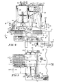
- Fig. 1 is a side elevation of a syringe of the type to be handled and inspected with the use of the present apparatus, shown in separated relation with an upper chuck having an expandable insert and in relation with a fragmental portion of a syringe carrier plate such as that used to support syringes in tubs as delivered from the filling apparatus;
- Fig. 2 is a diagrammatic plan view of the inspection apparatus in accordance with the present invention;
- Fig. 3 is a diagrammatic front elevation of such apparatus;
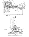
- Fig. 4 is a front elevation, with parts broken away and shown in section, of the loading portion of the apparatus shown in Figs. 2 and 3:
- Fig. 5 is a section taken on the line 5-5 of Fig. 4, showing the mechanism for feeding a 100-lot carrier of syringes to the gang chuck;
- Fig. 6 is a plan view, with parts broken away, taken on the line 6-6 of Fig. 4;
- Fig. 7 is an end elevation of the loading mechanism shown in Figs. 4-6;
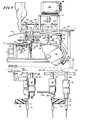
- Fig. 8 is a plan view, with parts broken away, of the turret, the infeed and outfeed star transfer wheels, the spinner belt, and the angled delivery wheel which delivers the vertically disposed syringes to a horizontal outfeed conveyor;
- Fig. 9 is a front elevation of the apparatus shown in Fig. 8;
- Fig. 10 is a vertical section showing a rotatable chuck and its mounting;
- Fig. 11 is a view taken on the line 11-11 of Fig. 8 showing the cam and rail mechanism which lifts the rotary chucks out of engagement with the syringes at the outfeed star wheel and drops the chucks into engagement with the syringes at the infeed star wheel;
- Fig. 12 is a vertical section showing the angle-delivery wheel, taken on the line 12-12 of Fig. 8; and
- Fig. 13 is an elevation at the first insnec- tion station.
- The
syringe 10 shown in Fig. 1 comprises atubular body 12 having a reduced lower end to which aneedle 14 is attached and which carries aneedle cap 16 for sealing and protecting the needle. Thebody 12 is filled with aninjectable liquid 18 stoppered by apiston 20 spaced a short distance below the upper open end of thebody 12. The upper end of the body carries aperipheral finger flange 22 for engagement by the user's fingers during hypodermic administration. For purposes of handling such syringes during loading, agang chuck bar 24 carries a series ofinflatable inserts 26 adapted to freely enter the open upper ends of thesyringe bodies 12 and to be expanded into gripping engagement with such bodies by air pressure supplied through anair passage 28 in thechuck bar 24. - The present invention contemplates that a group of
such syringes 10 will be supplied for loading into the inspection apparatus in asyringe carrier plate 30 of the type shown at the bottom of Fig. 1. This has a plurality ofupstanding collars 32, each adapted to loosely receive thetubular body 12 of asyringe 10 and to engage beneath thefinger flange 22 of the syringe to support the syringe in a depending vertical position. - . The inspection apparatus shown diagrammatically in Figs. 2 and 3 comprises a LOADING section, an INFEED conveyor and star wheel, a TURRET, a SPIN belt, a first inspection station Sl, a second inspection station S2, a DELIVERY wheel, and an OUTFEED conveyor. For convenience, the several parts of the apparatus are mounted at four different levels designated A to D.
- It is contemplated that syringes will be delivered to the inspection apparatus in 100-lot groups in
tubs 34, with the syringes supported in an upperremovable carrier plate 30 in ten alternately staggered rows of ten syringes each. The loading section comprises a loading table 36 having a series ofsupport bars 38 on which a syringe carrier plate with its 100-lot syringes is loaded manually. When the operator initiates a loading cycle, the loading table 36 positions the first row ofsyringes 10 beneath agang clutch 24 which stands in an elevated position above a pair of retractedconveyor rails 40. Thegang chuck 24 then moves downward, between the retractedrails 40, to enter its teninflatable inserts 26 in the upper ends of the tensyringes 10 in such first row. Air is then applied from anair valve 25 to the gang chuck to inflate the inserts causing them to clutch the syringes, and thegang chuck 24 is raised then to a position above theconveyor rails 40, and the rails are advanced to lie alongside thebodies 12 of the syringes and beneath theirupper flanges 22. The actuating air is then cut off from the gang chuck, and a stripper is actuated to ensure release of the syringes onto therails 40. The row of syringes thus deposited on therails 40 is then pushed forward onto the infeed conveyor. Meanwhile, the table 36 is moved transversely and jogged longitudinally to align the next row of syringes for pick-up by the gang chuck. - The infeed conveyor comprises one fixed
side rail 42 and a continuously drivenbelt 44, whic= acts to advance the syringes toward the infeed star -heel 46. Such wheel feeds the syringes, in spaced and timed relation, to a transfer point X at which they are transferred to a series ofchucks 48 on theturret 50. Thechucks 48 move with the turret past aspin belt 52 which rapidly rotates the syringes as they approach the first inspection station S-1. A stabilizing bar, not here shown, stabilizes the syringes during their spinning. The chucks pass beyond thespin belt 52 so that the syringes stop spinning while theliquid 18 in the syringes continues its rotation so as to cause solid particles therein to be suspended and observable at the inspection station. If such particles are observed in a syringe, the inspector manually pulls the syringe from the inflatable insert by which it is held on its chuck and drops it into a chute for rejects. The turret then carries the chucks and their suspended syringes past a second inspection station S-2, where the chucks may roll along astationary control belt 54 which causes the chucks and the syringes to rotate slowly as they traverse the second inspection station. - The
turret 50 then carries the chucks and syringes to a transfer point Y at which they are transferred to an outfeedstar wheel 56, to which the chucks release their syringes for movement by such outfeed star wheel to thedelivery wheel 58. This is disposed at an angle of 45° and has a conical edge face at 45° to its plane. The edge face is formed with a series of syringe-receiving pockets, which move from a vertical position at the transfer point Z of tangency with thestar wheel 56 to ahorizontal position 180° therefrom so as to carry the syringes from their depending vertical position at that transfer point to a horizontal delivery position at the bottom of thedelivery wheel 58. The horizontal syringes are then released at that point onto anoutfeed conveyor 60. - As more fully shown in Figs. 4, 5, and 6, the loading table 36 is mounted for sliding transverse movement on a pair of ways or
bars 62 which themselves are mounted for movement longitudinally of the load carrier on a pair ofbars 64 supported at level A of the machine. The table is driven transversely by achain 66 secured to it by aconnector 68 and strung aroundidler sprockets 70 coaxial with the longitudinal slide bars 64. Thechain 66 is driven from afirst motor 72 through a drive train which includes agear box 74, but is connected to that drive train through an electromagnetic clutch 76 so that after a carrier plate has been unloaded, the table is released for manual movement to its loading position shown in full lines in Fig. 5. The pair oftransverse bars 62 are connected by alink 78 to ajogger cam device 80, driven at half speed from the same drive train, for purposes of shifting the table longitudinally to align offset rows of syringes with the gang chuck. - The
gang chuck 24 is mounted on aram 82 carried.by bars 84 which are reciprocated vertically by acam box 86 mounted at level B of the machine. The cam box is driven through asprocket 87 by a chain 88 from avertical shaft 90 connected to the gear box '4 so as to be synchronized with the drive train from themotor 72. Theshaft 90 carries acam 91 for actuat-ng theair valve 25 which controls the air supply through theair line 89 to thegang chuck 24. Thegang chuck 24 carries astripper plate 92 which is biased to retracted position bysprings 94 between thechuck 24 and aplate 96 which, in the raised position of theganc chuck 24, is in a position to be actuated by astripper cam 98 on anelevated shaft 100.Such shaft 100 is driven by achain 102 from agear box 104 driven by thevertical shaft 90. Thatsame gear box 104 is connected also by achain 106 to drive acam 108 which operates to retract apusher arm 110. Such arm is mounted on a pivot 111 and is connected to adrive spring 115 which drives it through a forward stroke when permitted to do so by thecam 108. The lower end of thepusher arm 110 is connected by alink 112 to apusher element 114 mounted on a slide bar carried with the rearretractable rail 40 and adapted to push along therails 40syringes 10 deposited on it by thegang chuck 24. Thepusher arm 110 is reciprocated through a pusher stroke in timed sequence with the other operations, and moves the syringe from theretractable rails 40 to the powered conveyor formed by therail 42 andbelt 44. - As shown in Figs. 6 and 7, the
retractable rails 40 are carried byshafts 41 reciprocable incam boxes 116 which are driven bychains 118 fromgearboxes 120 driven by theelevated shaft 100. Thecam boxes 116 are operative to retract themovable rails 40 from their closed positions shown in Fig. 7 to their open positions shown in Fig. 6 in timed sequence to permit thegang chuck 24 to move downward between them to pick up a row of syringes from thesyringe carrier 30 on the loading table 36. When the row of syringes have been lifted, thecam boxes 116 then move therails 40 to a closed position for supporting thesyringes 10, air is cut off from the chuck, and the chuck then releases the syringes onto such rails. Thestripper 92 acts to ensure such release. - When a row of ten syringes on the
rails 40 have been moved by the pusher l14 onto the live conveyor 42-44, they are then continuously moved or urged forward by the continuous movement of thebelt 44, which is driven by its ownseparate motor 45. The live conveyor 42-44 delivers the syringes to a pair ofrails 122 which support the syringes for movement to theinfeed star wheel 46. The syringes on such rails are fed to such star wheel and separated into spaced positions for transfer to such star wheel by atiming screw 124 synchronized with thestar wheel 46. Thestar wheel 46 includes a peripheral series of spacedseats 126 to receive syringes fed thereto from therails 122 by thetiming screw 124. Syringes transferred to the star wheel are held in theseats 126 by aguide bar 127 for delivery to the chucks carried by theturret 50. - As shown in Figs. 8-10, the
turret 50 is in the form of a circular disk fixed to the lower end of amain shaft 130 mounted in abearing 132 on aplatform 134 at level C, above level B of the conveyor mechanism andinfeed star wheel 46 shown in Figs. 4, 6, and 7. Thedrive shaft 130 is driven from above through areduction gearbox 136 andsecond motor 138 mounted at level D on a platform elevated above theplatform 134. Themain shaft 130 carries asprocket wheel 142 which is connected by achain 144 to adrive sprocket 146 on theshaft 147 of theinfeed star wheel 46 and to asprocket 148 on theshaft 149 of theoutfeed star wheel 56 so that such star wheels will be driven in timed sequence with the turret. Thechain 144 is held in engagement with thedrive speocket 142 byidlers 143 in an arrangement which causes the star wheel shafts to rotate counterclockwise when the turret is driven clockwise as viewed in Fig. 8. Theturret 50 includes a peripheral series of dependinghollow spindle shafts 140 which in turn support the rotatable and axiallymovable chucks 48 which carry the syringes through the inspection path. - As shown in Fig. 10, each
chuck 48 comprises a generally cylindrical body mounted in rotatable and vertically movable relation on ahollow spindle 140 fixed in theturret 50. The spindle contains anaxial air passage 146 and is sealed to the spindle by anannular gasket 148. Air pressure will thrust the chuck downward. Athrust bearing 150 mounted on the spindle within acounterbore 152 in the upper end of the chuck body bears against a retainingring 154 to limit downward movement of the chuck. The thrust bearing is of substantially shorter length than thecounterbore 152 so that thechuck 48 is movable upward on thespindle 140 through a limited distance which provides sufficient axial movement of thechuck 48 to engage and disengage the chuck from the open ends of the syringes. - The bottom end of the
chuck 48 carries anexpandable insert 156, like theinsert 26 on thegang chuck 24 as shown in Fig. 1, and is adapted to clutch the chuck to asyringe 10 to carry it through the inspection path. Thechuck 48 is formed intermediate its length with aV groove 158 for the reception of the V-shapedspin belt 52. The chuck also has a conicallower face 160 adapted to engage alift cam 162 for lifting thechuck 48 to disengage itsexpandable insert 156 from asyringe 10 at the end of the inspection path, and to ride in elevated position along acam rail 163 as the chuck travels to the infeed transfer point at the start of the inspection path. Similarly, thechuck 48 has atop end face 164 adapted for engagement with a down-thrustcam 165 shown diagrammatically in Fig. 10 to ensure downward movement of the chuck to engage its expandable insert in a syringe at the beginning of the inspection path. Thecams spinner belt 52 is trained around a pair of angularly spaced idler pulleys 168 and thedrive pulley 170 of an independent spin-drive motor 172. - As shown in Figs. 8 and 9, the upper end of each
chuck spindle 140 is connected by anair tube 174 to an individual valve pocket in avalve plate 176 which rides in sealed relation with a manifold 178 connected to a source of air under pressure as by anair line 179. The manifold is formed with an annular cavity of limited angular extent designed to supply air under pressure to the several valve pockets and thence to the spindles and theexpandable inserts 156 of thechucks 48 during a predetermined angular movement of theturret 50 and to shut off air during the balance of such angular movement, as indicated in Fig. 8. - As shown in Figs. 8 and 11, the
cam rail 163 referred to in connection with Fig. 10 extends generally from the outfeed transfer point Y between theturret 50 and theoutfeed star wheel 56 to the infeed transfer point X between theturret 50 and theinfeed star wheel 46. Between these two transfer points, thecam rail 163 holds thechucks 48 in elevated position, so that theirexpandable inserts 156 are above the level of the upper ends ofsyringes 10 carried by theinfeed star wheel 46. The infeed transfer point X between theinfeed star wheel 46 and theturret 50 is substantially on a line connecting the axes of such star wheel and turret, where the path of syringes carried by theinfeed star wheel 46 is tangent to and momentarily coincident with the path of thechucks 48 on the turret. At such point, thecam bar 163 is terminated so as to release eachchuck 48 from its elevated position to allow the chuck to drop downward to engage itsexpandable insert 156 in thesyringe 10 which is then positioned below the chuck by theinfeed star wheel 46. The downthrust cam 165 is located at this point to ensure such downward movement of the chuck into engagement with the syringe. Air is applied then, and the syringe then is gripped by the chuck, with the chuck in its downmost position, and the syringe is transferred to the chuck to be carried thereby along the inspection path. - As shown in Fig. 8, movement of the
turret 50 first carries thechucks 48, with syringes suspended thereon, into engagement with thespin belt 52 so that the chucks and syringes are rapidly spun as they move toward the first inspection static; S-1. As they approach such station, they leave thebelt 52, and friction then causes the chucks tc stop rotating. This stops the spinning of the syringe oodles, but the liquid contained therein continues to spin thereby suspending any solid particles for observation during the inspection. - From the first inspection station S-1, the chucks and their suspended
syringes 10 are carried to the second inspection station S-2, where the chucks come into engagement with astationary belt 180 which engages in thegrooves 158 of the chucks and causes the chucks to roll along such belt and to slowly rotate the suspendedsyringes 10 as they pass the second inspection station. - The turret then carries the chucks and their syringes to the outfeed transfer point Y for transfer to the
outfeed star wheel 56. As they approach such star wheel, thesyringes 10 move between a pair of exit rails 182 adapted to support them in further travel. The air supply to the chucks is then cut off, so that the inflatable inserts in the syringes deflate releasing the syringes for separation from the chucks. The inserts remain in the chucks, however, to continue to move the syringes with the turret to the outfeed transfer point Y. At this point, the syringes engage inseats 184 in theoutfeed star wheel 56, the exit rails l82 terminate, and the chucks engage the upward- slopingcam face 162 on the cam at therail 163. Suchupward cam 162 lifts the chucks on their spindles a distance d (Fig. 10) sufficient to disengage their deflatedinserts 156 from the syringes so that the syringes are free to travel with theoutfeed star wheel 56. ThE chucks continue to be held in elevated position by therail 163 throughout their travel from the outfeed transfer point Y at theoutfeed star wheel 56 to the infeed transfer point X at theinfeed star wheel 46. The chucks then drop into newly infed syringes at the transfer point X at the start of the inspection path, as described above. - The syringes engaged in the
seats 184 in theoutfeed star wheel 56 are retained therein by aguide bar 186 so as to be carried in depending vertical positions through 180° of travel to a transfer point Z to thedelivery wheel 58. As best seen in Fig. 12,such delivery wheel 58 is carried by adrive shaft 188 at a 45° angle, so that the wheel moves in a plane at an opposite 45° angle. The edge face of thedelivery wheel 58 lies on a 90° cone and at 45° to the plane of the wheel. Such edge is formed with a series ofpockets 190, spaced to receive the succession of syringes delivered thereto by theoutfeed star wheel 56. Theseats 190 are at a 45° angle to the plane of the 45°delivery wheel 58 so that they are vertically disposed at the transfer point Z and adapted to receive thesyringes 10 in depending vertical position from theoutfeed star wheel 56. The syringes transferred to thedelivery wheel 58 are retained in thepockets 190 by aguide rail 192 extending through 180° about the delivery wheel. The angularly heldsyringes 10 are thus carried through 180° of travel in the delivery wheel, from their vertical positions at the top of such wheel to horizontal positions at the bottom of the wheel, as shown in Fig. 12. At this point, =he rail 192 terminates, and the syringes drop out of thepockets 190 in thedelivery wheel 58 onto anoitfeed conveyor 194. Desirably, such conveyor is composed of a series ofbuckets 196 shaped to receive indi-idual syringes and to support them in predetermined horizontal positions for conveyance to subsequent processing apparatus, such as a rod-inserting or labeling apparatus. - As shown in Figs. 8 and 13, at the first inspection station S-1, the
syringes 10 are carried in depending position across atranslucent screen 196 illuminated from behind by a series offluorescent tubes 198 so as to be inspected against back lighting. As the syringes enter the inspection station, the syringes have left the spinningbelt 52 and have stopped their rapid rotation, but theirliquid contents 18 are still rotating sufficiently to suspend solid particles in the liquid so as to be observable in such back lighting. If the inspector observes the presence of unwanted particles in any syringe, or any other defect, the defective syringe manually is pulled off the inflated insert of its supporting chuck and is dropped into achute 200, leading to areject box 202. - The second inspection station S-2 similarly is provided with a
reject chute 204, shown in Fig. 8. At this station, the syringes are front-lighted, for example, by alight tube 203. The chucks roll along thestationary belt 180 so that they and their suspended syringes rotate slowly with the liquid content of the syringes quiescent. This permits the syringes to be observed from all sides for the detection of cracks, inadequate fill level, misshapen pistons, and other gross defects. Both at this station and at the first inspection station A, the syringes are presented for inspection in a continuously moving series of a plurality of closely spaced syringes so that a comparative inspection can be carried out to reveal readily particular syringes which differ markedly from other adjacent syringes in the series. - Operation of the loading section of the inspection apparatus is as follows: With such apparatus as shown in Figs. 4-7 at rest, the drive train from the
first motor 72 will be inactive, and the electromagnetic clutch 76 controlling the movements of the loading table 36 will be released so that such table is free for manual movement. The operator manually moves such table to the left to its loading position as shown in full lines in Fig. 5, and loads asyringe carrier 30 onto the supportingbars 38 of that table. In this position, the table will position the first row of syringes in the carrier in the same plane as and immediately below theinflatable inserts 26 of thegang chuck 24 carried by theram 82, and the table will be in a position to close alimit switch 206 to condition the loading cycle to begin. The table 36 also will be longitudinally in its OUT position as shown in full lines in Fig. 5 so that the syringes in the first row of thecarrier 30 will be aligned immediately below thoseinflatable inserts 26, as shown in Fig. 7. Therails 40 will be retracted, and thepusher 114 will be in its rearward position to the left as shown in Fig. 4. The operator then actuates a start button, and the loading operation proceeds as follows: - (1) The chuck ram and
gang chuck 24 descend between the retracted rails 40 to engage the syringes of the first row. - (2) The
cam 91 actuates theair valve 25 to supply air pressure to the gang chuck to inflate theinserts 26 to grip the syringes. - (3) The chuck ram then rises to lift the syringes to between the rails 40 (Fig. 4).
- (4) The rails close to their conveyor position beneath the
flanges 22 of the syringes (Fig. 7). - (5) The
cam 91 actuates thevalve 25 to cut off and vent the air pressure on the gang chuck so as to deflate thechuck insert 26. - (6) The
stripper cam 98 depresses thestripper 92 to ensure that the syringes are disengaged from thegang chuck 24 and dropped onto the closed rails 40. - (7) The
pusher 114 linked to thepusher arm 110 is driven by thedrive spring 115 through a forward stroke to move the syringes on therails 40 forward onto the live conveyor formed by therail 42 and the movingbelt 44. Such conveyor then carries the syringes forward toward theinfeed star wheel 46, and the pusher returns to its retracted position as shown in full lines in Fig. 4. - (8) The
rails 40 are retracted so that they are again open for a new cycle. - (9) After the row of syringes has been elevated as in step (3) above, to clear the load table, the
table drive chain 66 is actuated to step the load table 36 forward to bring the second row of syringes in thecarrier 30 into the plane of thegang chuck 24. - (10) Concurrently, the table jogger mechanism 78-80 moves the table from its OUT position shown in full lines in Fig. 5 to its IN position shown in dotted lines, so as to align the syringes of that offset second row with the
inflatable inserts 26 of thegang chuck 24. - (11) The mechanism then repeats the loading cycle of items 1-10 above to load the successive rows of syringes onto the conveyor rails 40 and then to the live conveyor 42-44.
- (l2) During each successive cycle, the table 36 is advanced and is jogged between its IN and OUT positions to align the next successive rows of syringes with the inflatable inserts of the chuck.
- The loading cycles as described are repeated until all ten rows of syringes in the
carrier 30 have been removed and loaded onto the live conveyor 42-44. The table 36 in its final position for loading the tenth row of syringes engages alimit switch 208 which initiates a control cycle to cause the loading sequence to cease when that tenth row has been loaded onto the rails and then onto the live conveyor 42-44. The clutch 76 controlling the drive to the loading table 36 then is disengaged and the operator then manually moves the table 36 back to its starting position where it conditions thelimit switch 206 for a subsequent loading sequence. The operator removes the unloadedcarrier 30 and replaces it with anew carrier 30 containing a new lot of ten rows of ten syringes each. The loading sequence then is repeated. Thus, a continuous supply of syringes is supplied to the infeed live conveyor 42-44. - In the operation of the inspection portion of the apparatus, shown in Figs. 8 and 9, the
syringes 10 carried forward on the live conveyor 42-44 are fed in spaced relation by thetiming screw 124 to theseats 126 of theinfeed star wheel 46, which carries them to the infeed transfer point X. At point X, chucks 48 on the turret drop off therail 163 to engage theirinflatable inserts 156 in the syringes and the inserts are inflated to grip the syringes. The chucks then carry the syringes along the inspection path, first traveling along thespin belt 52 which drives the chucks to spin rapidly the syringes. The chucks then leave such belt and the syringe rotation stops while liquid in them continues to rotate and suspend solid particles as the syringes traverse the first inspection station. Defective syringes are removed manually from the chucks and dropped into thechute 200 for rejects. The syringes on the chucks then are carried to the second inspection station S-2 where the chucks are rolled along thestationary belt 180 to cause the syringes to be rotated slowly as they pass in series through that inspection station. The syringes then are carried by the chucks to the exit rails 182, where the air is cut off from theinflatable inserts 156 to allow the syringes to be transferred at point Y to theoutfeed star wheel 56 as the chucks are elevated out of engagement with the syringes by thecam 162. Thestar wheel 156 carries the syringes through l80° to a transfer point Z at which they are transferred to thepockets 190 of theangular delivery wheel 58 which carries and tilts them from a vertical position at the top of such wheel to a horizontal position at the bottom of such wheel. At that point, the syringes are dropped into the receivingcavities 195 of thebuckets 196 of theoutfeed conveyor 194.
Claims (10)
and table drive means (62, 64, 66, 68, 70, 72) for moving said table stepwise to position said rows successively in operative relation with said gang clutch (24) for removing the syringes of the successive rows to said infeed conveyor (42, 44).
Priority Applications (1)
| Application Number | Priority Date | Filing Date | Title |
|---|---|---|---|
| AT83302432T ATE35385T1 (en) | 1982-05-03 | 1983-04-29 | DEVICE FOR CHECKING INJECTION SYRINGES. |
Applications Claiming Priority (2)
| Application Number | Priority Date | Filing Date | Title |
|---|---|---|---|
| US373979 | 1982-05-03 | ||
| US06/373,979 US4456115A (en) | 1982-05-03 | 1982-05-03 | Syringe inspection apparatus |
Publications (3)
| Publication Number | Publication Date |
|---|---|
| EP0093592A2 true EP0093592A2 (en) | 1983-11-09 |
| EP0093592A3 EP0093592A3 (en) | 1984-10-24 |
| EP0093592B1 EP0093592B1 (en) | 1988-06-29 |
Family
ID=23474727
Family Applications (1)
| Application Number | Title | Priority Date | Filing Date |
|---|---|---|---|
| EP83302432A Expired EP0093592B1 (en) | 1982-05-03 | 1983-04-29 | Apparatus for the inspection of syringes |
Country Status (5)
| Country | Link |
|---|---|
| US (1) | US4456115A (en) |
| EP (1) | EP0093592B1 (en) |
| JP (1) | JPS5940866A (en) |
| AT (1) | ATE35385T1 (en) |
| DE (1) | DE3377200D1 (en) |
Cited By (1)
| Publication number | Priority date | Publication date | Assignee | Title |
|---|---|---|---|---|
| EP3882611A3 (en) * | 2020-03-17 | 2021-09-29 | Manuel A. Soto | A pre-filled parenteral drug inspection station and method of using the same |
Families Citing this family (16)
| Publication number | Priority date | Publication date | Assignee | Title |
|---|---|---|---|---|
| JPH01182742A (en) * | 1988-01-13 | 1989-07-20 | Mitsubishi Electric Corp | Semiconductor device appearance inspection machine |
| US6168009B1 (en) | 1995-12-28 | 2001-01-02 | Fuji Machine Mfg. Co. Ltd. | Apparatus for positioning electronic component holder head and apparatus for transferring electronic component |
| DE19604100C2 (en) * | 1996-02-06 | 1997-12-18 | Bosch Gmbh Robert | Device for handling fillable tubular objects arranged in an upwardly open container |
| US7392638B2 (en) * | 2000-08-10 | 2008-07-01 | Baxa Corporation | Method, system, and apparatus for handling, labeling, filling, and capping syringes with improved cap |
| EP1313644B1 (en) | 2000-08-10 | 2007-12-19 | Baxa Corporation | Article for handling, labeling, filling, and capping syringes |
| EP1669096A1 (en) * | 2004-12-08 | 2006-06-14 | Moller & Devicon A/S | Method, tray and apparatus for handling syringes |
| WO2007130809A2 (en) * | 2006-05-06 | 2007-11-15 | Volodymyr Brodskyy | An automatic injectable drug mixing device |
| WO2010098323A1 (en) * | 2009-02-25 | 2010-09-02 | テルモ株式会社 | Pre-filled syringe manufacturing method and pre-filled syringes |
| EP2381246A1 (en) * | 2010-04-26 | 2011-10-26 | Becton Dickinson France | Device, kit and method for inspection of an article |
| IT1401847B1 (en) * | 2010-10-14 | 2013-08-28 | Marchesini Group Spa | METHOD AND SYSTEM TO TRANSFER FRAGILE CONTAINERS FROM A CONTAINER TO A PACKAGING MACHINE |
| DE102011113358A1 (en) | 2011-09-15 | 2013-03-21 | Groninger & Co. Gmbh | Method and device for filling and closing pharmaceutical objects |
| WO2014179776A1 (en) | 2013-05-03 | 2014-11-06 | Becton, Dickinson And Company | Flow pathway subassembly |
| WO2019041037A1 (en) * | 2017-09-01 | 2019-03-07 | Ats Automation Tooling Systems Inc. | Method and apparatus for part transfer and transport in an assembly line |
| CN110102508B (en) * | 2019-05-28 | 2024-04-02 | 佛山职业技术学院 | Automatic feeding and discharging device of infusion connector and airtight detection device |
| CN113391619B (en) * | 2021-06-15 | 2023-04-14 | 绍兴浩晨自动化设备有限公司 | Quick automatic quality inspection device of temperature controller |
| CN113731831B (en) * | 2021-11-02 | 2022-02-08 | 常州医疗器材总厂股份有限公司 | Syringe detection device and detection method |
Family Cites Families (14)
| Publication number | Priority date | Publication date | Assignee | Title |
|---|---|---|---|---|
| US2268098A (en) * | 1939-09-30 | 1941-12-30 | Rca Corp | Bottle inspection apparatus |
| GB713770A (en) * | 1951-10-05 | 1954-08-18 | Crown Cork Company Ltd | Improvements in or relating to devices for grasping loads for lifting or lowering |
| US2936798A (en) * | 1953-09-10 | 1960-05-17 | Cps Mfg Company | Packaging machine for flowable material |
| CH364215A (en) * | 1957-04-27 | 1962-08-31 | Certus Maschbau Gmbh | Internal bottle gripping device |
| US3528544A (en) * | 1967-10-02 | 1970-09-15 | Eisai Co Ltd | Method for inspecting liquids for detection of foreign solid matters |
| US3548745A (en) * | 1968-06-21 | 1970-12-22 | Sun Chemical Corp | Mandrel assembly for continuous can printing |
| DE1956035C3 (en) * | 1969-11-07 | 1978-11-16 | Zinser Textilmaschinen Gmbh, 7333 Ebersbach | Pin-like gripper of a tube gripping device |
| US3780492A (en) * | 1971-02-05 | 1973-12-25 | A C I Operations | Apparatus for packing bottles, jars or like into cases |
| US3863763A (en) * | 1971-10-30 | 1975-02-04 | Richter Gedeon Vegyeszet | Equipment for the inspection of filled ampoules |
| JPS5219798B2 (en) * | 1971-12-22 | 1977-05-30 | ||
| US3701410A (en) * | 1972-09-01 | 1972-10-31 | Walter A Shields | Conveying vials in a straight path |
| SE385566B (en) * | 1973-05-16 | 1976-07-12 | J Nordqvist | SUBJECT TO WHEN PACKING A NUMBER, IN CROSS-SIGNIFICANTLY ROUND FOREMAL, PLACE THESE IN A MAINLY PARALLEL-PIPEDIC FORMATION WITH THE FOREMAL ORGANIZED IN SKRA JEMTE DEVICE FOR PERFORMING THE SET |
| US3970201A (en) * | 1975-06-23 | 1976-07-20 | Stowell Industries Inc. | Bottle gripper |
| US4076113A (en) * | 1976-11-24 | 1978-02-28 | Shields Walter A | Apparatus for simultaneously reorienting and transporting articles |
-
1982
- 1982-05-03 US US06/373,979 patent/US4456115A/en not_active Expired - Fee Related
-
1983
- 1983-04-29 DE DE8383302432T patent/DE3377200D1/en not_active Expired
- 1983-04-29 AT AT83302432T patent/ATE35385T1/en active
- 1983-04-29 EP EP83302432A patent/EP0093592B1/en not_active Expired
- 1983-04-30 JP JP58077370A patent/JPS5940866A/en active Granted
Cited By (1)
| Publication number | Priority date | Publication date | Assignee | Title |
|---|---|---|---|---|
| EP3882611A3 (en) * | 2020-03-17 | 2021-09-29 | Manuel A. Soto | A pre-filled parenteral drug inspection station and method of using the same |
Also Published As
| Publication number | Publication date |
|---|---|
| JPH0479668B2 (en) | 1992-12-16 |
| EP0093592A3 (en) | 1984-10-24 |
| EP0093592B1 (en) | 1988-06-29 |
| US4456115A (en) | 1984-06-26 |
| DE3377200D1 (en) | 1988-08-04 |
| JPS5940866A (en) | 1984-03-06 |
| ATE35385T1 (en) | 1988-07-15 |
Similar Documents
| Publication | Publication Date | Title |
|---|---|---|
| EP0093592B1 (en) | Apparatus for the inspection of syringes | |
| JP4290305B2 (en) | Continuous bag feeder | |
| US5096357A (en) | Apparatus for removing yarn bobbins and depositing them on a peg trolley | |
| US3946884A (en) | Method for transporting textile yarn packages | |
| US8925289B2 (en) | Machine for filling artificial insemination straws with semen | |
| US20040261358A1 (en) | System and method for bandoliering syringes | |
| EP0064843A2 (en) | Vial inspection machine | |
| CN1092640A (en) | Unloading and conveyor systems for equipment for coating flat tablets with edible gum | |
| JPH049488B2 (en) | ||
| EP0462497A1 (en) | Apparatus for erecting containers | |
| KR20140001743A (en) | Receptacle supply device | |
| US4772174A (en) | Bobbin transporting device | |
| EP1035023A1 (en) | Article conveying device | |
| US4500247A (en) | Syringe inspection apparatus | |
| JPS581636B2 (en) | Capsule wrinkles | |
| US20160075459A1 (en) | Method and device for handling elongated articles | |
| EP0113126A1 (en) | A process and system for automatic handling of yarn reels | |
| US3570668A (en) | Apparatus for testing and classifying bobbins | |
| JP2000318714A (en) | Intermittent container discharge device in continuous filling and packaging system | |
| CN209554328U (en) | A kind of vertical arrangement battery zinc-can automatic disc filling carloader | |
| JPH0610006B2 (en) | Cigarette inspection equipment | |
| CN217865234U (en) | Boxing production line | |
| CN115447864B (en) | A cartoning production line | |
| CN104053601A (en) | Method and device for handling bags combined into bundles | |
| CN210029105U (en) | Automatic feeding device of ampoule bottle light inspection machine |
Legal Events
| Date | Code | Title | Description |
|---|---|---|---|
| PUAI | Public reference made under article 153(3) epc to a published international application that has entered the european phase |
Free format text: ORIGINAL CODE: 0009012 |
|
| 17P | Request for examination filed |
Effective date: 19830502 |
|
| AK | Designated contracting states |
Designated state(s): AT BE CH DE FR GB IT LI LU NL SE |
|
| PUAL | Search report despatched |
Free format text: ORIGINAL CODE: 0009013 |
|
| AK | Designated contracting states |
Designated state(s): AT BE CH DE FR GB IT LI LU NL SE |
|
| 17Q | First examination report despatched |
Effective date: 19860604 |
|
| D17Q | First examination report despatched (deleted) | ||
| GRAA | (expected) grant |
Free format text: ORIGINAL CODE: 0009210 |
|
| AK | Designated contracting states |
Kind code of ref document: B1 Designated state(s): AT BE CH DE FR GB IT LI LU NL SE |
|
| REF | Corresponds to: |
Ref document number: 35385 Country of ref document: AT Date of ref document: 19880715 Kind code of ref document: T |
|
| REF | Corresponds to: |
Ref document number: 3377200 Country of ref document: DE Date of ref document: 19880804 |
|
| ET | Fr: translation filed | ||
| ITF | It: translation for a ep patent filed | ||
| PLBE | No opposition filed within time limit |
Free format text: ORIGINAL CODE: 0009261 |
|
| STAA | Information on the status of an ep patent application or granted ep patent |
Free format text: STATUS: NO OPPOSITION FILED WITHIN TIME LIMIT |
|
| 26N | No opposition filed | ||
| ITTA | It: last paid annual fee | ||
| PGFP | Annual fee paid to national office [announced via postgrant information from national office to epo] |
Ref country code: GB Payment date: 19920331 Year of fee payment: 10 |
|
| PGFP | Annual fee paid to national office [announced via postgrant information from national office to epo] |
Ref country code: CH Payment date: 19920424 Year of fee payment: 10 Ref country code: AT Payment date: 19920424 Year of fee payment: 10 |
|
| PGFP | Annual fee paid to national office [announced via postgrant information from national office to epo] |
Ref country code: FR Payment date: 19920429 Year of fee payment: 10 |
|
| PGFP | Annual fee paid to national office [announced via postgrant information from national office to epo] |
Ref country code: SE Payment date: 19920430 Year of fee payment: 10 Ref country code: NL Payment date: 19920430 Year of fee payment: 10 Ref country code: LU Payment date: 19920430 Year of fee payment: 10 Ref country code: DE Payment date: 19920430 Year of fee payment: 10 |
|
| PGFP | Annual fee paid to national office [announced via postgrant information from national office to epo] |
Ref country code: BE Payment date: 19920525 Year of fee payment: 10 |
|
| EPTA | Lu: last paid annual fee | ||
| PG25 | Lapsed in a contracting state [announced via postgrant information from national office to epo] |
Ref country code: LU Free format text: LAPSE BECAUSE OF NON-PAYMENT OF DUE FEES Effective date: 19930429 Ref country code: GB Effective date: 19930429 Ref country code: AT Effective date: 19930429 |
|
| PG25 | Lapsed in a contracting state [announced via postgrant information from national office to epo] |
Ref country code: SE Effective date: 19930430 Ref country code: LI Effective date: 19930430 Ref country code: CH Effective date: 19930430 Ref country code: BE Effective date: 19930430 |
|
| BERE | Be: lapsed |
Owner name: ELI LILLY AND CY Effective date: 19930430 |
|
| PG25 | Lapsed in a contracting state [announced via postgrant information from national office to epo] |
Ref country code: NL Effective date: 19931101 |
|
| NLV4 | Nl: lapsed or anulled due to non-payment of the annual fee | ||
| PG25 | Lapsed in a contracting state [announced via postgrant information from national office to epo] |
Ref country code: FR Effective date: 19931229 |
|
| REG | Reference to a national code |
Ref country code: CH Ref legal event code: PL |
|
| PG25 | Lapsed in a contracting state [announced via postgrant information from national office to epo] |
Ref country code: DE Effective date: 19940101 |
|
| GBPC | Gb: european patent ceased through non-payment of renewal fee |
Effective date: 19930429 |
|
| REG | Reference to a national code |
Ref country code: FR Ref legal event code: ST |
|
| EUG | Se: european patent has lapsed |
Ref document number: 83302432.6 Effective date: 19931110 |