EP0093577A1 - Winkelpositionssensoren - Google Patents
Winkelpositionssensoren Download PDFInfo
- Publication number
- EP0093577A1 EP0093577A1 EP83302387A EP83302387A EP0093577A1 EP 0093577 A1 EP0093577 A1 EP 0093577A1 EP 83302387 A EP83302387 A EP 83302387A EP 83302387 A EP83302387 A EP 83302387A EP 0093577 A1 EP0093577 A1 EP 0093577A1
- Authority
- EP
- European Patent Office
- Prior art keywords
- link member
- sensor according
- fixing means
- angular position
- axis
- Prior art date
- Legal status (The legal status is an assumption and is not a legal conclusion. Google has not performed a legal analysis and makes no representation as to the accuracy of the status listed.)
- Withdrawn
Links
- 230000008878 coupling Effects 0.000 claims abstract description 43
- 238000010168 coupling process Methods 0.000 claims abstract description 43
- 238000005859 coupling reaction Methods 0.000 claims abstract description 43
- 239000011159 matrix material Substances 0.000 description 4
- 230000004075 alteration Effects 0.000 description 3
- 230000003287 optical effect Effects 0.000 description 2
- 238000003491 array Methods 0.000 description 1
- 238000010276 construction Methods 0.000 description 1
- 238000005259 measurement Methods 0.000 description 1
- 230000009466 transformation Effects 0.000 description 1
Images


Classifications
-
- F—MECHANICAL ENGINEERING; LIGHTING; HEATING; WEAPONS; BLASTING
- F41—WEAPONS
- F41G—WEAPON SIGHTS; AIMING
- F41G3/00—Aiming or laying means
- F41G3/22—Aiming or laying means for vehicle-borne armament, e.g. on aircraft
- F41G3/225—Helmet sighting systems
-
- G—PHYSICS
- G01—MEASURING; TESTING
- G01B—MEASURING LENGTH, THICKNESS OR SIMILAR LINEAR DIMENSIONS; MEASURING ANGLES; MEASURING AREAS; MEASURING IRREGULARITIES OF SURFACES OR CONTOURS
- G01B21/00—Measuring arrangements or details thereof, where the measuring technique is not covered by the other groups of this subclass, unspecified or not relevant
- G01B21/22—Measuring arrangements or details thereof, where the measuring technique is not covered by the other groups of this subclass, unspecified or not relevant for measuring angles or tapers; for testing the alignment of axes
-
- G—PHYSICS
- G01—MEASURING; TESTING
- G01B—MEASURING LENGTH, THICKNESS OR SIMILAR LINEAR DIMENSIONS; MEASURING ANGLES; MEASURING AREAS; MEASURING IRREGULARITIES OF SURFACES OR CONTOURS
- G01B5/00—Measuring arrangements characterised by the use of mechanical techniques
- G01B5/24—Measuring arrangements characterised by the use of mechanical techniques for measuring angles or tapers; for testing the alignment of axes
Definitions
- This invention relates to angular position sensors.
- the invention relates to angular position sensors adapted to produce outputs which are a measure of the relative angular position of two bodies, one body normally defining a co-ordinate reference frame.
- helmet sight systems detect the line of sight of an observer, typically an aircraft pilot, from a measurement of the position of a helmet worn by the observer.
- a system may be used to enable a pilot to direct a weapon or other device, e.g. a camera, towards a target simply by looking at the target.
- Known helmet sight systems use either mechanical angular position sensors or optical angular position sensors using light sources mounted on the helmet and arranged to direct light beams onto fixed light sensor arrays.
- an angular position sensor for sensing the relative angular position of first and second bodies
- first and second fixing means for attachment of the sensor to said first and second bodies respectively; a link member; first and second coupling means whereby the first and second fixing means are respectively connected to said link member for angular movement about respective spaced points lying on an axis defined by said link member, each coupling means permitting angular movement of the associated fixing means about a first axis passing through the associated said point and transverse to said axis defined by the link member and a second axis passing through the associated said point and transverse to and rotatable about said first axis; first and second angle sensing means each of which is associated with a respective one of said first and second coupling means and produces first and second outputs which are respectively representative of treangular position of the associated fixing means about the associated said first and second axes; and third coupling means whereby said first and second fixing means may be moved translationally in at least one direction with respect to one another without altering
- the senor further includes a fourth coupling means in said link member permitting relative angular movement of said first and second fixing means about the axis defined by said link member; and a third angle sensing means associated with said fourth coupling means which produces an electrical output which is representative of the relative angular position of said first and second fixing means about said axis defined by said link member.
- Said third coupling means may comprise a linear coupling incorporated in said link member so that the spacing between said points may be expanded or contracted.
- said link member is suitably of telescopic form.
- said third coupling means may comprise a linear coupling incorporated in at least one of said fixing means.
- said first axes are preferably parallel to one another, and are preferably orthogonal to the axis defined by said link member.
- first and second axes are preferably the same in each said coupling means, the first and second axes preferably being orthogonal in each coupling means.
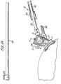
- the senor provides electrical outputs providing an indication of the angular position of a helmet 1, with respect to a co-ordinate reference frame fixed with respect to a vehicle in which the wearer of the helmet is travelling.
- the helmet is provided with sighting means (not shown) operative in use to direct the helmet wearer to maintain his line of sight in a fixed, predetermined attitude with respect to the helmet 1, so that the sensor outputs are indicative of the angle of the line of sight of the helmet wearer in the co-ordinate reference frame.
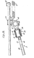
- the sensor comprises a telescopic link arm 3 one end of which is coupled via means 5 to a fixing plate 7 which is secured to the helmet 1.
- the coupling means 5 includes a U-shaped frame member 9 secured to the arm 3.
- a second tubular frame member 11 is mounted between the two limbs 13 of the frame member 9 by means of bearings 15 for rotation about a first axis which intersects the axis of the arm 3 at right angles at a point beyond the end of the arm.
- Within the frame member 11 there is mounted a third frame member 17 by means of bearings 19 for rotation about a second axis which is rotatable about the first axis and intersects the first axis at right angles at the point at which the first axis intersects the axis of the arm 3.
- the frame member 17 is also dovetailed to the plate 7.
- the coupling means 5 is associated with angle sensing means comprising two synchros 21 and 23.
- One of the synchros 21 is secured to the frame member 17 with its rotor axis coaxial with the second axis, i.e. the axis of rotation of the frame member 17 with respect to the frame member 11, the rotor of the synchro 21 being fixed to a lug 25 of the frame member 11.
- the other synchro 23 is secured to the frame member 11 with its rotor axis coaxial with the first axis, i.e. the axis of rotation of the frame member 11 with respect to the frame member 9, the rotor of the synchro 23 being fixed to a lug 27 of the frame member 9.
- the arm 3 comprises two tubular members 29 and 31 slidingly mounted one within the other by means of a linear bearing 33, the frame member 9 being secured to the inner tubular member 29.
- the coupling means 35 comprises an outer frame member 37 secured to the tubular member 31 and within which there is mounted a further frame member 39 by means of bearings 41 for rotation about the axis of the arm 3.
- the coupling means 35 is associated with angle sensing means comprising a synchro 43 mounted on the frame member 35 with its rotor axis coaxial with the axis of the arm 3.
- the rotor of the synchro 43 is secured to one end of a rod 45 which is splined into the nearer end of the inner tubular member 29 of the arm 3.
- the inner frame member 39 of the coupling means 35 is secured to a U-shaped frame member 47 which forms part of a further coupling means 49 which essentially of identical construction to the coupling means 5, the member 47 corresponding to the member 9 of the coupling means 5.
- the coupling means 49 is associated with angle sensing means comprising two synchros 51 and 53 corresponding to the synchros 21 and 23 associated with the coupling means 5.
- a frame member 55 of the coupling means 49 corresponding to the frame member 17 of coupling means 5 is mounted by way of twin linear bearings 57 on a pair of parallel rods 59, the rods 59 being secured at their ends to the vehicle frame 61 by means of fixing plates 63.
- the plate 7 is secured to the helmet 1 by means of snap-on pillars 69 which protrude through the outer skin 75 of the helmet 1 (see Figure 5 and 6).
- the rods 59 are disposed with their axes parallel to the normal, i.e. a datum line of sight of the wearer of the helmet 1 and the plate 7 is secured to the helmet 1 in a position such that when the helmet wearer directs his line of sight in the normal direction the synchro 23 and the corresponding synchro 53 in the coupling means 49 produce equal and opposite output signals.
- the rods 59 are disposed vertically above the helmet so that the synchros 21 and 51 produce equal and opposite output signals when the helmet wearer directs his line of sight in the normal direction.
- the output of synchros 51 and 53 provide an indication of the angular position of the axis of the arm 3 with respect a co-ordinate reference frame fixed with respect to the vehicle frame.
- the synchros 21, 23 and 43 provide an indication of the angular position of the helmet 1 with respect to the axis of the arm 3.
- the position of mounting of the rods 59 allows limited translational movement of the helmet 1 in a direction parallel to the axes of the rods without alteration of the output of any of the synchros 21, 23, 43, 51 and 53.
- the telescopic form of the arm 3 allows limited translational movement of the helmet 1 in the direction of the axis of the arm without alteration of the output of any of the synchros.
- translational movement of the helmet 1 can be effected to a limited extent, sufficient for normal requirements of a wearer travelling in a vehicle, without changing the difference in the outputs of synchros 21 and 51, the difference in the outputs of synchros 23 and 53 or the output of the synchro 43.
- a linear bearing arrangement corresponding to bearings 57 and rods 59 may be alternatively or additionally incorporated in the means whereby the sensor is fixed to the helmet 1.
- the attitude matrix Tuv of the helmet is where s and c mean sine and cosine respectively.
- the matrix Tuv has nine components but only five of these T 11' T 12 , T 13' T23 and T 33 are required to give helmet azimuth, elevation and rolls angles A, B and C, as follows: where: and
Landscapes
- Engineering & Computer Science (AREA)
- Physics & Mathematics (AREA)
- General Physics & Mathematics (AREA)
- Aviation & Aerospace Engineering (AREA)
- General Engineering & Computer Science (AREA)
- Helmets And Other Head Coverings (AREA)
- Length Measuring Devices With Unspecified Measuring Means (AREA)
Applications Claiming Priority (2)
| Application Number | Priority Date | Filing Date | Title |
|---|---|---|---|
| GB8212310 | 1982-04-28 | ||
| GB8212310 | 1982-04-28 |
Publications (1)
| Publication Number | Publication Date |
|---|---|
| EP0093577A1 true EP0093577A1 (de) | 1983-11-09 |
Family
ID=10530034
Family Applications (1)
| Application Number | Title | Priority Date | Filing Date |
|---|---|---|---|
| EP83302387A Withdrawn EP0093577A1 (de) | 1982-04-28 | 1983-04-27 | Winkelpositionssensoren |
Country Status (3)
| Country | Link |
|---|---|
| US (1) | US4486955A (de) |
| EP (1) | EP0093577A1 (de) |
| GB (1) | GB2122731B (de) |
Cited By (3)
| Publication number | Priority date | Publication date | Assignee | Title |
|---|---|---|---|---|
| GB2235293A (en) * | 1989-08-25 | 1991-02-27 | Ferranti Int Signal | Target information transmission system |
| EP0413525A3 (en) * | 1989-08-15 | 1991-08-07 | Paliac Aktiengesellschaft | Aiming system |
| CN112214062A (zh) * | 2020-09-28 | 2021-01-12 | 中国航空工业集团公司洛阳电光设备研究所 | 一种手柄俯仰角度快速调节机构 |
Families Citing this family (12)
| Publication number | Priority date | Publication date | Assignee | Title |
|---|---|---|---|---|
| US4571834A (en) * | 1984-02-17 | 1986-02-25 | Orthotronics Limited Partnership | Knee laxity evaluator and motion module/digitizer arrangement |
| GB2161121B (en) * | 1984-07-04 | 1987-09-09 | Ferranti Plc | Apparatus for the removal of helmet-mounted equipment |
| SE8503151D0 (sv) * | 1985-06-24 | 1985-06-24 | Se Produkter | Anordning for detektering av relativa rorelser och/eller legen for en kroppsdel eller liknande |
| GB8526386D0 (en) * | 1985-10-25 | 1986-10-01 | Secr Defence | Aircrew headgear |
| IL79736A0 (en) * | 1986-08-15 | 1986-11-30 | Kibbutz Ein Shemer | Body motion controller for toy system |
| GB2198216B (en) * | 1986-11-25 | 1991-01-23 | Sony Corp | Digital video effects units. |
| US5339906A (en) * | 1993-01-08 | 1994-08-23 | Deere & Company | Positon feedback mechanism for an implement |
| US5430953A (en) * | 1993-02-18 | 1995-07-11 | Queen's University At Kingston | Apparatus for detecting or measuring movements in geological formations and other massive structures |
| EP0883195A1 (de) * | 1997-06-03 | 1998-12-09 | BARR & STROUD LIMITED | Kopfnachführsystem, das eine LED mit fluoreszierender Beschichtung aufweist |
| US6519860B1 (en) * | 2000-10-19 | 2003-02-18 | Sandia Corporation | Position feedback control system |
| US11079201B2 (en) * | 2017-11-29 | 2021-08-03 | Lonnie Dale Tustison | Firearm accessory holder |
| DE102020205071A1 (de) | 2020-04-22 | 2021-10-28 | Fraunhofer-Gesellschaft zur Förderung der angewandten Forschung eingetragener Verein | Vorrichtung zur Erfassung der Relativlage zwischen einem an einer Tragstruktur angebrachten Befestigungsanker und einem endseitig am Befestigungsanker angebrachten, gespannten Tragseil |
Family Cites Families (5)
| Publication number | Priority date | Publication date | Assignee | Title |
|---|---|---|---|---|
| US3051047A (en) * | 1958-12-23 | 1962-08-28 | Creusot Forges Ateliers | Device for the suspension of a telescope on a vehicle |
| US3262210A (en) * | 1963-05-06 | 1966-07-26 | Sperry Rand Corp | Control system |
| US3184600A (en) * | 1963-05-07 | 1965-05-18 | Potter Instrument Co Inc | Photosensitive apparatus for measuring coordinate distances |
| US3561125A (en) * | 1968-02-23 | 1971-02-09 | Linear Motion Technology Inc | Three-dimensional position indicating sensor |
| US4258474A (en) * | 1979-10-22 | 1981-03-31 | Teledyne Industries, Inc. | Method and apparatus for aiding measurement of preformed tubes |
-
1983
- 1983-04-26 US US06/488,747 patent/US4486955A/en not_active Expired - Fee Related
- 1983-04-27 EP EP83302387A patent/EP0093577A1/de not_active Withdrawn
- 1983-04-27 GB GB08311444A patent/GB2122731B/en not_active Expired
Non-Patent Citations (2)
| Title |
|---|
| Patent Abstracts of Japan Vol. 4, no. 149, 21 October 1980 Page 123P32 & JP-A-55-99002 * |
| PROCEEDING OF THE SID, vol. 19, no. 4, 1978, Los Angeles L. RUSSO "Helmet mounted visually coupled systems", pages 181-185 * |
Cited By (3)
| Publication number | Priority date | Publication date | Assignee | Title |
|---|---|---|---|---|
| EP0413525A3 (en) * | 1989-08-15 | 1991-08-07 | Paliac Aktiengesellschaft | Aiming system |
| GB2235293A (en) * | 1989-08-25 | 1991-02-27 | Ferranti Int Signal | Target information transmission system |
| CN112214062A (zh) * | 2020-09-28 | 2021-01-12 | 中国航空工业集团公司洛阳电光设备研究所 | 一种手柄俯仰角度快速调节机构 |
Also Published As
| Publication number | Publication date |
|---|---|
| GB2122731B (en) | 1985-10-16 |
| US4486955A (en) | 1984-12-11 |
| GB2122731A (en) | 1984-01-18 |
Similar Documents
| Publication | Publication Date | Title |
|---|---|---|
| EP0093577A1 (de) | Winkelpositionssensoren | |
| US4085910A (en) | Dual mode optical seeker for guided missile control | |
| CA1338747C (en) | Automatic landing and navigation system | |
| DE3426505C2 (de) | ||
| DE60107196T2 (de) | Stabilisierte gemeinsame kardanische Aufhängung | |
| DE69516871T2 (de) | Verfahren zum lokaliseren eines trieders im raum | |
| DE69318023T2 (de) | Ziel-und richtsystem fur eine bodenwaffenvorrichtung | |
| US4260187A (en) | Terminal guidance sensor system | |
| US5493392A (en) | Digital image system for determining relative position and motion of in-flight vehicles | |
| US4490724A (en) | Gimbal system with case mounted drives | |
| CN103196443B (zh) | 基于光流和附加信息的飞行体姿态测量方法与系统 | |
| CA2057625A1 (en) | Fault-tolerant inertial navigation system | |
| US5272422A (en) | Head equipment with articulated arm | |
| GB1578136A (en) | Helmet-mounted sights | |
| US3260849A (en) | Light sensitive orienting device | |
| EP0556487A1 (de) | Zusammenbau von Beschleunigungsmessaufnehmern zur Verwendung in einem Messystem für dreidimensionale Bewegungen eines festen Körpers | |
| IT8985009A1 (it) | Dispositivo di telemetria ottico-elettronica a base variabile | |
| CA1260121A (en) | Flight control apparatus | |
| CA1220962A (en) | Armour-plated turret | |
| US5075861A (en) | Integrated stabilized optical and navigation system | |
| US3516055A (en) | Internally gimbaled attitude indicator | |
| IT8948474A1 (it) | Servo sistema di azionamento per dispositivi di ricerca del bersaglio | |
| US5118185A (en) | Optical transceiver apparatus for dynamic boresight systems | |
| US3071977A (en) | Gyroscope system | |
| US2989672A (en) | Agins |
Legal Events
| Date | Code | Title | Description |
|---|---|---|---|
| PUAI | Public reference made under article 153(3) epc to a published international application that has entered the european phase |
Free format text: ORIGINAL CODE: 0009012 |
|
| AK | Designated contracting states |
Designated state(s): DE FR IT |
|
| 17P | Request for examination filed |
Effective date: 19840113 |
|
| STAA | Information on the status of an ep patent application or granted ep patent |
Free format text: STATUS: THE APPLICATION IS DEEMED TO BE WITHDRAWN |
|
| 18D | Application deemed to be withdrawn |
Effective date: 19851101 |
|
| RIN1 | Information on inventor provided before grant (corrected) |
Inventor name: MUNDY, ANTHONY CHARLES Inventor name: FISCHER, JEREMY FRANCIS Inventor name: PERRY, MICHAEL JOHN |