EP0093572A1 - Luft-Brennstoff-Mischvorrichtung - Google Patents
Luft-Brennstoff-Mischvorrichtung Download PDFInfo
- Publication number
- EP0093572A1 EP0093572A1 EP83302372A EP83302372A EP0093572A1 EP 0093572 A1 EP0093572 A1 EP 0093572A1 EP 83302372 A EP83302372 A EP 83302372A EP 83302372 A EP83302372 A EP 83302372A EP 0093572 A1 EP0093572 A1 EP 0093572A1
- Authority
- EP
- European Patent Office
- Prior art keywords
- combustion chamber
- liquid fuel
- air
- fuel
- frustrum
- Prior art date
- Legal status (The legal status is an assumption and is not a legal conclusion. Google has not performed a legal analysis and makes no representation as to the accuracy of the status listed.)
- Withdrawn
Links
- 239000000446 fuel Substances 0.000 title claims abstract description 69
- 238000002156 mixing Methods 0.000 title claims abstract description 13
- 238000002485 combustion reaction Methods 0.000 claims abstract description 54
- 239000007788 liquid Substances 0.000 claims abstract description 36
- 239000000203 mixture Substances 0.000 claims abstract description 16
- 239000007921 spray Substances 0.000 claims abstract description 8
- 238000000034 method Methods 0.000 claims description 4
- 238000005507 spraying Methods 0.000 claims 1
- 239000007789 gas Substances 0.000 description 4
- 239000003921 oil Substances 0.000 description 3
- 229910001220 stainless steel Inorganic materials 0.000 description 3
- 239000010935 stainless steel Substances 0.000 description 3
- IJGRMHOSHXDMSA-UHFFFAOYSA-N Atomic nitrogen Chemical compound N#N IJGRMHOSHXDMSA-UHFFFAOYSA-N 0.000 description 2
- QVGXLLKOCUKJST-UHFFFAOYSA-N atomic oxygen Chemical compound [O] QVGXLLKOCUKJST-UHFFFAOYSA-N 0.000 description 2
- 239000000567 combustion gas Substances 0.000 description 2
- 239000000295 fuel oil Substances 0.000 description 2
- 238000010438 heat treatment Methods 0.000 description 2
- 238000004519 manufacturing process Methods 0.000 description 2
- 239000001301 oxygen Substances 0.000 description 2
- 229910052760 oxygen Inorganic materials 0.000 description 2
- 125000006850 spacer group Chemical group 0.000 description 2
- 229910000831 Steel Inorganic materials 0.000 description 1
- VLYDPWNOCPZGEV-UHFFFAOYSA-M benzyl-dimethyl-[2-[2-[2-methyl-4-(2,4,4-trimethylpentan-2-yl)phenoxy]ethoxy]ethyl]azanium;chloride;hydrate Chemical compound O.[Cl-].CC1=CC(C(C)(C)CC(C)(C)C)=CC=C1OCCOCC[N+](C)(C)CC1=CC=CC=C1 VLYDPWNOCPZGEV-UHFFFAOYSA-M 0.000 description 1
- 238000001816 cooling Methods 0.000 description 1
- 239000000463 material Substances 0.000 description 1
- 229910052757 nitrogen Inorganic materials 0.000 description 1
- 230000005019 pattern of movement Effects 0.000 description 1
- 239000011819 refractory material Substances 0.000 description 1
- 239000010959 steel Substances 0.000 description 1
- 238000009834 vaporization Methods 0.000 description 1
- 230000008016 vaporization Effects 0.000 description 1
Images

Classifications
-
- F—MECHANICAL ENGINEERING; LIGHTING; HEATING; WEAPONS; BLASTING
- F23—COMBUSTION APPARATUS; COMBUSTION PROCESSES
- F23M—CASINGS, LININGS, WALLS OR DOORS SPECIALLY ADAPTED FOR COMBUSTION CHAMBERS, e.g. FIREBRIDGES; DEVICES FOR DEFLECTING AIR, FLAMES OR COMBUSTION PRODUCTS IN COMBUSTION CHAMBERS; SAFETY ARRANGEMENTS SPECIALLY ADAPTED FOR COMBUSTION APPARATUS; DETAILS OF COMBUSTION CHAMBERS, NOT OTHERWISE PROVIDED FOR
- F23M5/00—Casings; Linings; Walls
- F23M5/08—Cooling thereof; Tube walls
- F23M5/085—Cooling thereof; Tube walls using air or other gas as the cooling medium
-
- F—MECHANICAL ENGINEERING; LIGHTING; HEATING; WEAPONS; BLASTING
- F17—STORING OR DISTRIBUTING GASES OR LIQUIDS
- F17C—VESSELS FOR CONTAINING OR STORING COMPRESSED, LIQUEFIED OR SOLIDIFIED GASES; FIXED-CAPACITY GAS-HOLDERS; FILLING VESSELS WITH, OR DISCHARGING FROM VESSELS, COMPRESSED, LIQUEFIED, OR SOLIDIFIED GASES
- F17C9/00—Methods or apparatus for discharging liquefied or solidified gases from vessels not under pressure
- F17C9/02—Methods or apparatus for discharging liquefied or solidified gases from vessels not under pressure with change of state, e.g. vaporisation
-
- F—MECHANICAL ENGINEERING; LIGHTING; HEATING; WEAPONS; BLASTING
- F23—COMBUSTION APPARATUS; COMBUSTION PROCESSES
- F23C—METHODS OR APPARATUS FOR COMBUSTION USING FLUID FUEL OR SOLID FUEL SUSPENDED IN A CARRIER GAS OR AIR
- F23C6/00—Combustion apparatus characterised by the combination of two or more combustion chambers or combustion zones, e.g. for staged combustion
- F23C6/04—Combustion apparatus characterised by the combination of two or more combustion chambers or combustion zones, e.g. for staged combustion in series connection
- F23C6/045—Combustion apparatus characterised by the combination of two or more combustion chambers or combustion zones, e.g. for staged combustion in series connection with staged combustion in a single enclosure
-
- F—MECHANICAL ENGINEERING; LIGHTING; HEATING; WEAPONS; BLASTING
- F23—COMBUSTION APPARATUS; COMBUSTION PROCESSES
- F23C—METHODS OR APPARATUS FOR COMBUSTION USING FLUID FUEL OR SOLID FUEL SUSPENDED IN A CARRIER GAS OR AIR
- F23C7/00—Combustion apparatus characterised by arrangements for air supply
-
- F—MECHANICAL ENGINEERING; LIGHTING; HEATING; WEAPONS; BLASTING
- F17—STORING OR DISTRIBUTING GASES OR LIQUIDS
- F17C—VESSELS FOR CONTAINING OR STORING COMPRESSED, LIQUEFIED OR SOLIDIFIED GASES; FIXED-CAPACITY GAS-HOLDERS; FILLING VESSELS WITH, OR DISCHARGING FROM VESSELS, COMPRESSED, LIQUEFIED, OR SOLIDIFIED GASES
- F17C2265/00—Effects achieved by gas storage or gas handling
- F17C2265/02—Mixing fluids
- F17C2265/025—Mixing fluids different fluids
Definitions
- This invention relates to an air fuel mixing device and a method for creating a stable flame, both for use in a combustor that can be used for burning liquid fuel for purposes such as gas turbine engines, heating units and/or for the vaporization of cryogenic liquids such as nitrogen.
- a liquid fuel such as oil is introduced into a primary combustion chamber where it is combined with air to form a combustible mixture.
- the air is generally supplied by means of admitting primary combustion air into the combustion chamber where it mixes with the atomized liquid fuel.
- swirling vanes are commonly used to swirl the air as it impinges upon the stream of liquid fuel from the fuel nozzle.
- the number and size of holes is established as needed to obtain the proper swirl to such primary combustion air.
- Gas Turbine Engineering Handbook Section 5 "Combustors” by Herbert R Hazard.
- the present art suggests a swirling motion of the primary air and the creation of a low pressure area at the combustion axis to continually recirculate the flame toward the fuel nozzle.
- the mixing device of the invention allows a low cost design for mixing air and liquid fuel over a wide range of fuel/air mixtures.
- the flame itself is very stable and is not sensitive to an inbalance in flow or pressures of numerous jets of incoming air.
- the flame stability is also unaffected by changes in flow of the secondary combustion air.
- the converging cone of primary combustion air is uniform, it is able to pull the root flame away from the inner walls or surfaces of a combustor including a mixing device according to the invention and thus even the inner surfaces of such combustor can be constructed of normal steel, i.e. 50 mil. plate of 310 stainless steel and not require refractory materials.
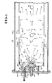
- a combustor 30 for use with a liquid fuel such as oil.
- the combustor 30 is preferably cylindrical in shape and includes an outer shell 32 generally constructed of 12 gauge stainless steel.
- An outer shell 32 generally constructed of 12 gauge stainless steel.
- a liner 34 constructed of relative thin (0.050 inches stainless steel) and within which is contained a primary combustion chamber (or zone) 36 and a secondary combustion chamber (or zone) 38 where the hot gases from primary combustion chamber 36 are mixed with secondary air to complete the combustion process.
- the air for the combustion taking place in primary combustion chamber 36 and for completion of combustion in secondary combustion chamber 38 is supplied by a fan, not shown, and air passes through the annular passage 40 between liner 34 and outer shell 32 and which flow of air serves to cool the liner 34 and outer shell 32. As noted in Fig.l, the air passes through the annular passage 40 in the direction of arrows 42.
- An end plate 44 closes off one end of the combustor 30 and is fitted into the ends of the liner 34 and the outer shell 32 to close the same.
- a fitted nozzle holder 46 Centrally located through end plate 44 is a fitted nozzle holder 46 which, among other functions, channels air for determining the pattern of fuel distribution for liquid fuel injected by means of the fuel nozzle 48.
- the nozzle holder 46 is more fully shown in Figs 2 and 3 in cross section and end view, respectively, and generally comprises a body 50 having an opening 52, one end of which opening 52 opens into an angled opening 54 at an angle of approximately 90° about its central axis, as shown, and further comprises a plurality of radially oriented apertures 56 which open into the angled opening 54.
- a recess 58 is formed in body 50 in order to receive the fuel nozzle 48 (not shown in Figs 4 and 5).
- the fuel nozzle 48 may be of conventional commercial design as supplied by the Delavan Corporation Nozzle Model No. 27710-1 and which is rated for a fuel consumption at 50 lbs/hr of JP4 fuel oil at a supply pressure of 100 psig.
- the particular fuel nozzle 48 is of a design that sprays out the atomized fuel oil in the shape of a diverging hollow cone at a total angle of approximately 75 0 + 5° about its central axis. By passing air through the apertures 56, the liquid fuel is caused to swirl and produce a vortex flow in the primary combustion chamber 36.
- the outer surface 57 of the nozzle holder 46 is angled with respect to its central axis at approximately 30° thereto, or converges at a total angle with respect to its central axis of about 60° in the shape of a truncated cone.
- baffle plate 60 Surrounding the fuel nozzle 48 and nozzle holder 46 is a circular shaped baffle plate 60.
- the baffle 60 is shown in detail in Figs. 4 and 5, as well as shown assembled to combustor 30 in Fig.l.
- the baffle plate 60 is shown as generally circular in shape having an annular dished interior 62 and a central opening 64.
- the inner lip 66 of annular dished interior 62 is formed at an angle of about 30° to the central axis of the baffle plate 60 or a total angle of 60° in a converging conical configuration.
- the baffle plate 60 is coaxially mounted with respect to nozzle holder 46 and fuel nozzle 48 to the end plate 44 by means such as bolts 68 secured to the end plate 44 by nuts 70 and held in its predetermined position with respect to fuel nozzle 48 by spacers 72.
- bolts 68, spacers 72 and nuts 70 hold the baffle plate 60 in its fixed position through bolt holes 74 in baffle plate 60 and the further hole 76 in baffle plate 60 is used in connection with the incandescent ignitor assembly 78 the function of which will be later described.
- the flow of air for use in the primary combustion chamber 36 and the secondary combustion chamber 38 proceeds as follows.
- the primary air, or air actually used in the combustion of the liquid fuel passes along the annular passage 40 and enters plenum chamber 80 through a plurality of openings 82 in annular passage 40.
- the plenum chamber 80 is thus formed behind the baffle plate 60 and air is used from that plenum chamber 80 for a variety of purposes.
- a portion of the air from plenum chamber 80 passes through radially oriented apertures 56 in the nozzle holder 46 and such air used to create the swirling motion for the fuel injected into primary combustion chamber 36 from fuel nozzle 48.
- annular frustrum opening 86 Most of the air, however, from plenum chamber 80 passes through the annular frustrum opening 86 to serve as primary air to supply oxygen for the combustion of the liquid fuel. As noted, due to the design angles of the outer surface 57 of nozzle holder 46 and the inner lip 66 of baffle plate 60, that annular frustrum opening 86 converges in the direction toward the primary combustion chamber 36 at a total angle of about 60° about the central axis of the fuel nozzle 48.
- Secondary air Is- mixed with the hot combustion gases in secondary combustion chamber 38 to complete the combustion process and is admitted to the secondary combustion chamber 38 through a plurality of openings 87.
- the fuel is injected outwardly into the primary combustion chamber 36 by the fuel nozzle 48 in the pattern of a diverging hollow cone at a total angle of about 75 0 + 5 0 .
- the fuel is atomized by the fuel nozzle 48 in such predetermined pattern into small droplets to create, in certain zones, the combustible mixture of liquid fuel and air where combustion can actually take place.
- the primary air for supplying oxygen for the combustible mixture impinges upon.the hollow diverging cone-shaped pattern of liquid fuel through the converging annular frustrum opening 86, forming a pattern of movement generally as shown by the arrows in Fig. 1.
- the pattern of liquid fuel/air mixture thereby forms a zone of combustible mixture at zone 88 and which is a relatively stable, quiet zone protected by baffle plate 60 and out of the direct stream of the liquid fuel. That zone 88 thus contains a mixture that can readily be ignited by means of the incandescent ignitor assembly 78.
- the ignitor assembly 78 may be a conventional spark type of ignitor wherein a high voltage spark causes ignition of the liquid fuel/air mixture in zone 88 or, as shown, may include a cylindrical housing 90 having one end thereof fitted within an appropriate sized opening 92 in end plate 44, and the other end thereof just passing through the opening 76 in baffle plate 60.
- An incandescent or spark type ignitor 94 can be located within cylindrical housing 90 by means such as a threaded engagement for ease of assembly and removal at 95.
- the ignitor 94 includes a high resistance heating wire 96 to create a sufficiently high temperature to ignite the liquid fuel/air mixture in zone 88 within primary combustion chamber 36 and may be a commercially available glow plug such as Champion Type CH3.
- the flame maintains a very stable position and does not vary despite wide variations or chamges in levels of fuel flow.
- the stable flame pattern results from the primary air being supplied in the form of a converging annular frustrum that impinges in a uniform pattern around the diverging conical shaped spray of liquid fuel from fuel nozzle 48.
Landscapes
- Engineering & Computer Science (AREA)
- Mechanical Engineering (AREA)
- General Engineering & Computer Science (AREA)
- Chemical & Material Sciences (AREA)
- Combustion & Propulsion (AREA)
- Spray-Type Burners (AREA)
- Pressure-Spray And Ultrasonic-Wave- Spray Burners (AREA)
Applications Claiming Priority (2)
| Application Number | Priority Date | Filing Date | Title |
|---|---|---|---|
| US37278882A | 1982-04-28 | 1982-04-28 | |
| US372788 | 1982-04-28 |
Publications (1)
| Publication Number | Publication Date |
|---|---|
| EP0093572A1 true EP0093572A1 (de) | 1983-11-09 |
Family
ID=23469639
Family Applications (1)
| Application Number | Title | Priority Date | Filing Date |
|---|---|---|---|
| EP83302372A Withdrawn EP0093572A1 (de) | 1982-04-28 | 1983-04-26 | Luft-Brennstoff-Mischvorrichtung |
Country Status (4)
| Country | Link |
|---|---|
| EP (1) | EP0093572A1 (de) |
| JP (1) | JPS591915A (de) |
| AU (1) | AU1273483A (de) |
| ZA (1) | ZA832157B (de) |
Cited By (2)
| Publication number | Priority date | Publication date | Assignee | Title |
|---|---|---|---|---|
| GB2337102A (en) * | 1998-05-09 | 1999-11-10 | Europ Gas Turbines Ltd | Gas-turbine engine combustor |
| US20100015562A1 (en) * | 2008-07-16 | 2010-01-21 | Babington Robert S | Perforated flame tube for a liquid fuel burner |
Citations (4)
| Publication number | Priority date | Publication date | Assignee | Title |
|---|---|---|---|---|
| DE1094909B (de) * | 1958-05-17 | 1960-12-15 | Arthur Kuhlmann | Druckzerstaeubungsbrenner mit feststehendem Zerstaeuber fuer fluessige Brennstoffe |
| GB894470A (en) * | 1959-09-30 | 1962-04-26 | Gen Motors Corp | Improvements in flame tubes for burning liquid fuel in an air stream |
| DD57168A1 (de) * | 1966-08-09 | 1967-08-05 | B Projektow Przemyslu Cementowego | Ölbrenner |
| DE1751653B2 (de) * | 1967-07-04 | 1973-04-12 | Guerin, Robert Edmond; S.A. Union Generale De Distribution De Produits Petroliers U.G.D.; Paris | Brenner fuer fluessige brennstoffe |
-
1983
- 1983-03-23 AU AU12734/83A patent/AU1273483A/en not_active Abandoned
- 1983-03-25 ZA ZA832157A patent/ZA832157B/xx unknown
- 1983-04-26 EP EP83302372A patent/EP0093572A1/de not_active Withdrawn
- 1983-04-28 JP JP58076027A patent/JPS591915A/ja active Pending
Patent Citations (4)
| Publication number | Priority date | Publication date | Assignee | Title |
|---|---|---|---|---|
| DE1094909B (de) * | 1958-05-17 | 1960-12-15 | Arthur Kuhlmann | Druckzerstaeubungsbrenner mit feststehendem Zerstaeuber fuer fluessige Brennstoffe |
| GB894470A (en) * | 1959-09-30 | 1962-04-26 | Gen Motors Corp | Improvements in flame tubes for burning liquid fuel in an air stream |
| DD57168A1 (de) * | 1966-08-09 | 1967-08-05 | B Projektow Przemyslu Cementowego | Ölbrenner |
| DE1751653B2 (de) * | 1967-07-04 | 1973-04-12 | Guerin, Robert Edmond; S.A. Union Generale De Distribution De Produits Petroliers U.G.D.; Paris | Brenner fuer fluessige brennstoffe |
Non-Patent Citations (1)
| Title |
|---|
| RECKNAGEL/SPRENGER, "Taschenbuch fur Heizung + Klimatechnik", 1981/82, 61. Ausgabe VERLAG OLDENBURG page 1402, lines 21-24 * |
Cited By (5)
| Publication number | Priority date | Publication date | Assignee | Title |
|---|---|---|---|---|
| GB2337102A (en) * | 1998-05-09 | 1999-11-10 | Europ Gas Turbines Ltd | Gas-turbine engine combustor |
| US6151899A (en) * | 1998-05-09 | 2000-11-28 | Alstom Gas Turbines Limited | Gas-turbine engine combustor |
| US20100015562A1 (en) * | 2008-07-16 | 2010-01-21 | Babington Robert S | Perforated flame tube for a liquid fuel burner |
| US8622737B2 (en) * | 2008-07-16 | 2014-01-07 | Robert S. Babington | Perforated flame tube for a liquid fuel burner |
| US9234659B2 (en) | 2008-07-16 | 2016-01-12 | Robert S. Babington | Perforated flame tube for liquid fuel burner |
Also Published As
| Publication number | Publication date |
|---|---|
| JPS591915A (ja) | 1984-01-07 |
| AU1273483A (en) | 1983-11-03 |
| ZA832157B (en) | 1983-12-28 |
Similar Documents
| Publication | Publication Date | Title |
|---|---|---|
| US4938019A (en) | Fuel nozzle and igniter assembly | |
| US4773596A (en) | Airblast fuel injector | |
| KR100320164B1 (ko) | 가스 터빈 엔진용 저 nox버너 및 가스 터빈 엔진의 연소기내에서 액체연료를 연소시키는 방법 | |
| US4257763A (en) | Low NOx burner | |
| US2930192A (en) | Reverse vortex combustion chamber | |
| US4218020A (en) | Elliptical airblast nozzle | |
| US4815664A (en) | Airblast fuel atomizer | |
| EP0638768B1 (de) | Brennstoffdüse mit nicht-rotationssymmetrischer, sekundärer Zerstäubung | |
| JPS6161015B2 (de) | ||
| JP2002195563A (ja) | 燃焼器エミッションを減少させるための方法及び装置 | |
| US4780077A (en) | Flame retention head assembly for fuel burners | |
| US5267442A (en) | Fuel nozzle with eccentric primary circuit orifice | |
| US4014639A (en) | Recirculating vortex burner | |
| US4893475A (en) | Combustion apparatus for a gas turbine | |
| US5782079A (en) | Miniature liquid-fueled turbojet engine | |
| KR900000646A (ko) | 액체 연료 연소용 버너 | |
| US5431019A (en) | Combustor for gas turbine engine | |
| JPH06341611A (ja) | 燃焼からのNOx放出量を最小限に抑える方法およびバーナ | |
| US4887961A (en) | Radiant wall burner apparatus | |
| GB1563124A (en) | Gas turbine fuel injection systems | |
| GB2143938A (en) | Fuel burner for a gas turbine engine | |
| RU2056231C1 (ru) | Устройство для газоструйной резки материалов | |
| EP0093572A1 (de) | Luft-Brennstoff-Mischvorrichtung | |
| US5520535A (en) | Burner apparatus | |
| EP0093016A1 (de) | Glühzünder |
Legal Events
| Date | Code | Title | Description |
|---|---|---|---|
| PUAI | Public reference made under article 153(3) epc to a published international application that has entered the european phase |
Free format text: ORIGINAL CODE: 0009012 |
|
| AK | Designated contracting states |
Designated state(s): CH DE FR GB IT LI |
|
| RAP1 | Party data changed (applicant data changed or rights of an application transferred) |
Owner name: THE BOC GROUP, INC. |
|
| STAA | Information on the status of an ep patent application or granted ep patent |
Free format text: STATUS: THE APPLICATION IS DEEMED TO BE WITHDRAWN |
|
| 18D | Application deemed to be withdrawn |
Effective date: 19840710 |
|
| RIN1 | Information on inventor provided before grant (corrected) |
Inventor name: ROGAN, MILAN |