EP0093571A2 - Compact combustion apparatus - Google Patents
Compact combustion apparatus Download PDFInfo
- Publication number
- EP0093571A2 EP0093571A2 EP83302371A EP83302371A EP0093571A2 EP 0093571 A2 EP0093571 A2 EP 0093571A2 EP 83302371 A EP83302371 A EP 83302371A EP 83302371 A EP83302371 A EP 83302371A EP 0093571 A2 EP0093571 A2 EP 0093571A2
- Authority
- EP
- European Patent Office
- Prior art keywords
- combustion
- air
- chamber
- combustors
- gases
- Prior art date
- Legal status (The legal status is an assumption and is not a legal conclusion. Google has not performed a legal analysis and makes no representation as to the accuracy of the status listed.)
- Withdrawn
Links
Images

Classifications
-
- F—MECHANICAL ENGINEERING; LIGHTING; HEATING; WEAPONS; BLASTING
- F23—COMBUSTION APPARATUS; COMBUSTION PROCESSES
- F23D—BURNERS
- F23D11/00—Burners using a direct spraying action of liquid droplets or vaporised liquid into the combustion space
- F23D11/001—Spraying nozzle combined with forced draft fan in one unit
-
- F—MECHANICAL ENGINEERING; LIGHTING; HEATING; WEAPONS; BLASTING
- F17—STORING OR DISTRIBUTING GASES OR LIQUIDS
- F17C—VESSELS FOR CONTAINING OR STORING COMPRESSED, LIQUEFIED OR SOLIDIFIED GASES; FIXED-CAPACITY GAS-HOLDERS; FILLING VESSELS WITH, OR DISCHARGING FROM VESSELS, COMPRESSED, LIQUEFIED, OR SOLIDIFIED GASES
- F17C9/00—Methods or apparatus for discharging liquefied or solidified gases from vessels not under pressure
- F17C9/02—Methods or apparatus for discharging liquefied or solidified gases from vessels not under pressure with change of state, e.g. vaporisation
-
- F—MECHANICAL ENGINEERING; LIGHTING; HEATING; WEAPONS; BLASTING
- F23—COMBUSTION APPARATUS; COMBUSTION PROCESSES
- F23C—METHODS OR APPARATUS FOR COMBUSTION USING FLUID FUEL OR SOLID FUEL SUSPENDED IN A CARRIER GAS OR AIR
- F23C6/00—Combustion apparatus characterised by the combination of two or more combustion chambers or combustion zones, e.g. for staged combustion
- F23C6/04—Combustion apparatus characterised by the combination of two or more combustion chambers or combustion zones, e.g. for staged combustion in series connection
- F23C6/045—Combustion apparatus characterised by the combination of two or more combustion chambers or combustion zones, e.g. for staged combustion in series connection with staged combustion in a single enclosure
-
- F—MECHANICAL ENGINEERING; LIGHTING; HEATING; WEAPONS; BLASTING
- F23—COMBUSTION APPARATUS; COMBUSTION PROCESSES
- F23C—METHODS OR APPARATUS FOR COMBUSTION USING FLUID FUEL OR SOLID FUEL SUSPENDED IN A CARRIER GAS OR AIR
- F23C7/00—Combustion apparatus characterised by arrangements for air supply
- F23C7/02—Disposition of air supply not passing through burner
- F23C7/06—Disposition of air supply not passing through burner for heating the incoming air
-
- F—MECHANICAL ENGINEERING; LIGHTING; HEATING; WEAPONS; BLASTING
- F23—COMBUSTION APPARATUS; COMBUSTION PROCESSES
- F23D—BURNERS
- F23D23/00—Assemblies of two or more burners
-
- F—MECHANICAL ENGINEERING; LIGHTING; HEATING; WEAPONS; BLASTING
- F23—COMBUSTION APPARATUS; COMBUSTION PROCESSES
- F23M—CASINGS, LININGS, WALLS OR DOORS SPECIALLY ADAPTED FOR COMBUSTION CHAMBERS, e.g. FIREBRIDGES; DEVICES FOR DEFLECTING AIR, FLAMES OR COMBUSTION PRODUCTS IN COMBUSTION CHAMBERS; SAFETY ARRANGEMENTS SPECIALLY ADAPTED FOR COMBUSTION APPARATUS; DETAILS OF COMBUSTION CHAMBERS, NOT OTHERWISE PROVIDED FOR
- F23M5/00—Casings; Linings; Walls
- F23M5/08—Cooling thereof; Tube walls
- F23M5/085—Cooling thereof; Tube walls using air or other gas as the cooling medium
Definitions
- This invention relates to combustion apparatus and particularly to industrial combustion apparatus of the type wherein a liquid- fuel is burned in a combustion chamber in order to derive the heat from the combustion gases for a useful purpose.
- Such apparatus may serve a variety of purposes, such as industrial heating, boilers and also in the field to which the present invention is particularly suited, i.e. vaporizers for converting a liquid cryogenic substance such as liquid nitrogen into vapour to be used for various industrial applications including the servicing of oil wells.
- vaporizers for converting a liquid cryogenic substance such as liquid nitrogen into vapour to be used for various industrial applications including the servicing of oil wells.
- the unit In such applications as a vaporizer, the unit is generally required to be shipped to various locations and thereafter continually moved as its needs arise.
- One of the features desired of such equipment, is that it be compact and light so that movement is facilitated.
- a further advantage sought is the ability to control the turndown, or there preferably is some means by which the flame intensity, and thus overall heat generated for use, be variable such that the intensity may be reduced as the load or liquid cryogenic substance to be vaporized is correspondingly reduced.
- This aim is achieved by virtue of the use of a plurality of combustors, each having its own fuel nozzle, primary and secondary combustion chambers, and dilution chamber or ombustion chamber with primary and secondary combustion zones and dilution zone.
- a centrally located fan supplies primary, secondary and dilution air to all of the combustors that are typically radially oriented around the fan.
- the central fan typically delivers outside air into a cold plenum from which the air is delivered to an annular passage surrounding each of the combustors and thereafter travels along the length of each combustor in a direction countercurrent to the flow of hot gases in the combustor as those hot gases travel from the primary and secondary combustion chambers, where burning occurs, to the dilution chamber when the hot combustion gases are mixed and cooled by air admitted through openings from the annular passage.
- the hot gases typically continue from the dilution chamber into a hot plenum where the heated gases are mixed for delivery for some useful means.
- the heated gases are directed from the hot plenum through a series of baffles in a diffuser section and into a heat exchanger where they contact a tube bundle containing liquid nitrogen (or other cryogenic liquid) to be vaporized, before being exhausted by means of an exhaust plenum.
- the combustor may be constructed of thinner gauge steel, and thus less heavy materials than in conventional combustors.
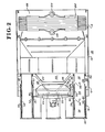
- FIG. 1 there is shown an isometric view of an oil-fired vaporizer 10 for vaporizing cryogenic liquids such as liquid nitrogen and which utilizes a combustion apparatus 12 designed in accordance with the present invention and which further includes additional sections including a diffuser section 14 and a heat exchanger 16, the function of which will be later explained.
- a combustion apparatus 12 designed in accordance with the present invention and which further includes additional sections including a diffuser section 14 and a heat exchanger 16, the function of which will be later explained.
- combustion apparatus 12 will be described initially with reference both to Fig.l and to Fig.2 wherein the combustion apparatus 12 is shown in cross-section view.
- a fan 22 Centrally positioned within the plurality of combustors 18 is a fan 22 which draws in outside air to supply the same for primary and secondary combustion as well as for dilution of the hot combustion gases.
- combustors 18 In Fig.l, two of the combustors 18 are shown in more detail, it being understood that all of the combustors 18 are similar. Those details include a fuel line 24 for supplying fuel oil for burning inside the combustor 18. In addition, cable 26 supplies electrical energy to an ignitor assembly 28. A flame detector 30 is used to monitor the presence or absence of a flame within combustor 18.
- Each combustor 18 has an end plate 32 and which is secured to the outer shell 34 of each combustor 18 by a strap clamp 36.
- the fan 22 is powered by a hydraulic motor 38 by means of a source of hydraulic fluid (not shown).
- Fan 22 has a shaft (not shown) on which is mounted a fan blade 42 and supported by a support 44 holding fan 22 in its central position with respect to combustors 18.
- the blades 42 When fan 22 is operated, the blades 42 are angled to draw in outside air and force that air in the direction of arrows 46 into cold plenum 48.
- the outer shell 34 is cylindrical and is held firmly in position by the frame 50 of combustion apparatus 12.
- a liner 52 constructed of a relatively thin (50 mil.) stainless steel and within which is contained (or defined) a primary combustion chamber (or zone) 54, a secondary combustion chamber (or zone) 56 where the hot gases from primary combustion chamber 54 are mixed with secondary air to complete the combustion process. The gases thus proceed to dilution chamber (or zone) 58 where the combustion gases are mixed with and cooled by additional air.
- the air for the combustion taking place in primary combustion chamber 54, for completion of combustion in secondary combustion chamber 56 and for dilution of the hot gases of combustion in dilution chamber 58 is forced, by the fan 22, through cold plenum 48 and thence into the annular passage 60 between liner 52 and outer shell 34 and which flow of air serves to cool the liner 52 and outer shell 34. As noted in Fig. 2, the air passes through the annular passage 60 in the direction of arrows 62.
- a fuel nozzle 64 Centrally located through end plate 32 is a fuel nozzle 64 which receives the fuel from fuel line 24 (Fig.l) and sprays that fuel into primary combustion chamber 54 for burning to produce heat.
- the fuel nozzle typically may be of conventional commercial design as supplied by the Delavan Corporation Nozzle Model No. 27710-1 rated for fuel consumption of 50 lbs/hr. of JP4 fuel oil at a supply pressure of 100 p.s.i.g. and which sprays out the atomized fuel oil in the shape of a hollow cone at a total angle of approximately 75° + 5° about its central axis.
- the outer surface 66 of the fuel nozzle 64 is angled with respect to its central axis at approximately 3 0 ° thereto, or converges at a total angle with respect to its central axis of about 60° in the shape of a truncated cone.
- a circular shaped baffle plate 68 Surrounding the fuel nozzle 64 is a circular shaped baffle plate 68 having a generally annular dished interior 70 and a central opening 72.
- the inner lip 74 of the annular dished interior 70 is formed at an angle generally paralleling the outer surface 66 of fuel nozzle 64, thereby forming an annular frustrum opening 76 therewith.
- the baffle plate 68 is coaxially mounted with respect to the fuel nozzle 64 by means such as bolts 78 secured to end plate 32 by nuts 80 and held in its predetermined position'with respect to fuel nozzle 64 by spacers 82.
- baffle plate 68 in its fixed position through holes 84 in baffle plate 68 and a further hole 86 is formed in baffle plate 68 for the ignition assembly 28.
- the flow of air for use in the primary combustion chamber 54, secondary combustion chamber 56 and dilution chamber 58 proceeds as follows.
- the primary air, or the air actually used in the initial combustion of the liquid fuel passes through the annular passage 60 and enters plenum chamber 88 through a plurality of openings 90 in liner 52.
- the plenum chamber 88 is thus formed behind the baffle plate 68 and a portion of air in that chamber leaks past the outer edge 92 of the baffle plate 68 and provides some cooling to the inner surface of liner 52 and protects liner 52 from direct action or contact.by the combustion gases of primary combustion chamber 54.
- annular frustrum opening 76 Most of the air, however, from plenum chamber 88 passes through the annular frustrum opening 76 to serve as primary air to supply oxygen for the combustion of the liquid fuel. As noted, the annular frustrum opening 76 converges in the direction of the primary combustion chamber 54 and travels toward and impinges upon, the diverging hollow conical spray of liquid fuel from fuel nozzle 64. Although the primary air has been described as being delivered to primary combustion chamber 54 in the shape of a converging annular frustrum, it should be noted that other means of introducing the primary air from plenum chamber 88 to the primary combustion chamber 54 may be used, such as a plurality of openings, without departing from the spirit of the present invention.
- Secondary air is mixed with the hot combustion gases in secondary combustion chamber 56 to complete the combustion process and that air also is provided from annular passage 60 by means of a plurality of openings 94 in liner 52, and still further air is provided for the dilution chamber 58 wherein that air is admitted from annular passage 60 by means of openings 96 to mix with the combustion gases to cool the same.
- the fuel is sprayed outwardly into the primary combustion chamber 54 by the fuel nozzle 64 and is atomized into small droplets in a predetermined pattern to create, in certain zones, the combustible mixture of liquid fuel and air when combustion can actually take place.
- the pattern forms a zone 98 of such combustible mixture which is a relatively stable, quiet zone protected by baffle plate 68 and can readily be ignited by means of the ignitor assembly 28.
- the ignitor assembly 28 may be of a conventional spark type of ignitor where a high voltage spark causes ignition of the liquid fuel/air mixture in zone 98.
- the heated gases from dilution chamber 58 thereafter are mixed together from the plurality of combustors 18 in a hot plenum 100 and thereafter in diffuser section 14 (Figs 1 and 2).
- the mixed hot gases are thereafter passed through heat exchanger 16 where the heat is used for vaporizing the liquid cryogenic substance.
- heat exchanger 16 there is a tube bundle 102 having an inlet 104 and an outlet 106 for receiving and discharging, respectively, liquid nitrogen and gaseous nitrogen for various uses.
- the diluted combustion gases exit the oil fired vaporizer 10 through exhaust plenum 108.
Landscapes
- Engineering & Computer Science (AREA)
- Mechanical Engineering (AREA)
- General Engineering & Computer Science (AREA)
- Chemical & Material Sciences (AREA)
- Combustion & Propulsion (AREA)
- Physics & Mathematics (AREA)
- Thermal Sciences (AREA)
- Combustion Of Fluid Fuel (AREA)
- Spray-Type Burners (AREA)
- Pressure-Spray And Ultrasonic-Wave- Spray Burners (AREA)
Abstract
A compact combustion apparatus 12 comprises a plurality of radially aligned combustors 18 surrounding a central fan 22. The fan 22 draws in air from the outside and provides the air for primary and secondary combustion as well as for cooling the gases of that combustion. Each combustor 18 receives the air forced from the central fan 22 by means of an annular passage 60 formed between the outer shell 4 of the combustor 18 and its liner 52. The outside air travels countercurrent to the flow of the combustion gases and serves to cool the combustor liner 52 and outer shell 34 of each combustor 16. In turn, that outside air is heated as it passes through the annular passage so that it is warmed before being introduced into combustion chamber (or zone) 34 of each combustor 18 to be mixed with atomized liquid fuel supplied from the respective nozzle 84 to form a combustibl mixture. Various holes 94 in the combustor liner 52 allow the air to enter a secondary combustion chamber (or zone) 56 as well as a dilution chamber (or zone) 58 to cool the gases of combustion for later use in transferring heat for various uses. In a preferred embodiment, the mixed combustion gases and outside air are passed through a heat exchanger 16 to utilize that heat to vaporize a liquid cryogenic substance such as nitrogen.
Description
- This invention relates to combustion apparatus and particularly to industrial combustion apparatus of the type wherein a liquid- fuel is burned in a combustion chamber in order to derive the heat from the combustion gases for a useful purpose.
- Such apparatus may serve a variety of purposes, such as industrial heating, boilers and also in the field to which the present invention is particularly suited, i.e. vaporizers for converting a liquid cryogenic substance such as liquid nitrogen into vapour to be used for various industrial applications including the servicing of oil wells.
- In such applications as a vaporizer, the unit is generally required to be shipped to various locations and thereafter continually moved as its needs arise. One of the features desired of such equipment, is that it be compact and light so that movement is facilitated.
- On the other hand, to achieve lightness and compactness, one does not want to sacrifice combustion intensity, that is, the unit, to be optimum, must still have a high combustion intensity in the light weight package.
- A further advantage sought is the ability to control the turndown, or there preferably is some means by which the flame intensity, and thus overall heat generated for use, be variable such that the intensity may be reduced as the load or liquid cryogenic substance to be vaporized is correspondingly reduced.
- It is an aim of the invention, which is defined in the appended claims, to provide a relatively lightweight, compact combustion apparatus that is particularly adapted to provide heat for vaporizing a liquid cryogenic material, yet the apparatus is capable of exhibiting a high combustion intensity.
- This aim is achieved by virtue of the use of a plurality of combustors, each having its own fuel nozzle, primary and secondary combustion chambers, and dilution chamber or ombustion chamber with primary and secondary combustion zones and dilution zone. A centrally located fan supplies primary, secondary and dilution air to all of the combustors that are typically radially oriented around the fan. The central fan typically delivers outside air into a cold plenum from which the air is delivered to an annular passage surrounding each of the combustors and thereafter travels along the length of each combustor in a direction countercurrent to the flow of hot gases in the combustor as those hot gases travel from the primary and secondary combustion chambers, where burning occurs, to the dilution chamber when the hot combustion gases are mixed and cooled by air admitted through openings from the annular passage. The hot gases typically continue from the dilution chamber into a hot plenum where the heated gases are mixed for delivery for some useful means. In a preferred embodiment of the invention the heated gases are directed from the hot plenum through a series of baffles in a diffuser section and into a heat exchanger where they contact a tube bundle containing liquid nitrogen (or other cryogenic liquid) to be vaporized, before being exhausted by means of an exhaust plenum.
- Owing the the nature of the central fan and countercurrent flow of the outside air in each of the combustors, construction of a relatively compact unit is facilitated and, partly because of the cooling by the outside air of the outer shell and liner it employs, the combustor may be constructed of thinner gauge steel, and thus less heavy materials than in conventional combustors.
- Also, the use of multiple combustors allows a wide turndown range: since all of the combustors provide heated gases to a common hot plenum, one or more of the combustors may be turned off completely for effective control of the heat furnished, in this case, to the heat exchanger.
- The invention will now be described by way of example with reference to the accompanying drawings in which:
- Fig. 1, is an isometric view of an oil-fired vaporizer for cryogenic liquids utilizing a combustion apparatus constructed in accordance with the present invention;
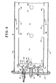
- Fig. 2, is a cross-sectional side view of the vaporizer of Fig.l; and
- Fig. 3, is an enlarged cross-sectional side view of a typical combustion chamber used in the vaporizer of Fig.l.
- Turning first to Fig. 1, there is shown an isometric view of an oil-fired
vaporizer 10 for vaporizing cryogenic liquids such as liquid nitrogen and which utilizes acombustion apparatus 12 designed in accordance with the present invention and which further includes additional sections including adiffuser section 14 and aheat exchanger 16, the function of which will be later explained. - The
combustion apparatus 12 will be described initially with reference both to Fig.l and to Fig.2 wherein thecombustion apparatus 12 is shown in cross-section view. - In Fig.l,
combustion apparatus 12 includes a plurality ofcombustors 18 which extend outwardly from amain frame 20. In the preferred embodiment themain frame 20 is octagonal in shape to accommodate eightcombustors 18; however, more orless combustors 18 may be used depending upon the requirements of the particular heat generating apparatus. - Centrally positioned within the plurality of
combustors 18 is afan 22 which draws in outside air to supply the same for primary and secondary combustion as well as for dilution of the hot combustion gases. - In Fig.l, two of the
combustors 18 are shown in more detail, it being understood that all of thecombustors 18 are similar. Those details include afuel line 24 for supplying fuel oil for burning inside thecombustor 18. In addition,cable 26 supplies electrical energy to anignitor assembly 28. Aflame detector 30 is used to monitor the presence or absence of a flame withincombustor 18. - Each
combustor 18 has anend plate 32 and which is secured to theouter shell 34 of eachcombustor 18 by astrap clamp 36. - Turning again to Fig.2, the
fan 22 is powered by ahydraulic motor 38 by means of a source of hydraulic fluid (not shown).Fan 22 has a shaft (not shown) on which is mounted afan blade 42 and supported by asupport 44holding fan 22 in its central position with respect tocombustors 18. - When
fan 22 is operated, theblades 42 are angled to draw in outside air and force that air in the direction ofarrows 46 intocold plenum 48. - In the construction of
combustor 18, shown in detail in Fig.3, theouter shell 34 is cylindrical and is held firmly in position by theframe 50 ofcombustion apparatus 12. Within theouter shell 34 which is also cylindrically shaped and coaxial therewith, is aliner 52 constructed of a relatively thin (50 mil.) stainless steel and within which is contained (or defined) a primary combustion chamber (or zone) 54, a secondary combustion chamber (or zone) 56 where the hot gases fromprimary combustion chamber 54 are mixed with secondary air to complete the combustion process. The gases thus proceed to dilution chamber (or zone) 58 where the combustion gases are mixed with and cooled by additional air. - The air for the combustion taking place in
primary combustion chamber 54, for completion of combustion insecondary combustion chamber 56 and for dilution of the hot gases of combustion indilution chamber 58 is forced, by thefan 22, throughcold plenum 48 and thence into theannular passage 60 betweenliner 52 andouter shell 34 and which flow of air serves to cool theliner 52 andouter shell 34. As noted in Fig. 2, the air passes through theannular passage 60 in the direction ofarrows 62. - Centrally located through
end plate 32 is afuel nozzle 64 which receives the fuel from fuel line 24 (Fig.l) and sprays that fuel intoprimary combustion chamber 54 for burning to produce heat. The fuel nozzle typically may be of conventional commercial design as supplied by the Delavan Corporation Nozzle Model No. 27710-1 rated for fuel consumption of 50 lbs/hr. of JP4 fuel oil at a supply pressure of 100 p.s.i.g. and which sprays out the atomized fuel oil in the shape of a hollow cone at a total angle of approximately 75° + 5° about its central axis. - As shown in Fig.3, the
outer surface 66 of thefuel nozzle 64 is angled with respect to its central axis at approximately 30° thereto, or converges at a total angle with respect to its central axis of about 60° in the shape of a truncated cone. - Surrounding the
fuel nozzle 64 is a circular shapedbaffle plate 68 having a generally annular dishedinterior 70 and a central opening 72. The inner lip 74 of the annular dishedinterior 70 is formed at an angle generally paralleling theouter surface 66 offuel nozzle 64, thereby forming an annular frustrum opening 76 therewith. - The
baffle plate 68 is coaxially mounted with respect to thefuel nozzle 64 by means such asbolts 78 secured toend plate 32 bynuts 80 and held in its predetermined position'with respect tofuel nozzle 64 byspacers 82. - In the preferred embodiment, three
such bolts 78,spacers 82 andnuts 80 hold thebaffle plate 68 in its fixed position throughholes 84 inbaffle plate 68 and afurther hole 86 is formed inbaffle plate 68 for theignition assembly 28. - As now may be seen in Figs. 2 and 3, the flow of air for use in the
primary combustion chamber 54,secondary combustion chamber 56 anddilution chamber 58 proceeds as follows. The primary air, or the air actually used in the initial combustion of the liquid fuel passes through theannular passage 60 and entersplenum chamber 88 through a plurality ofopenings 90 inliner 52. Theplenum chamber 88 is thus formed behind thebaffle plate 68 and a portion of air in that chamber leaks past theouter edge 92 of thebaffle plate 68 and provides some cooling to the inner surface ofliner 52 and protectsliner 52 from direct action or contact.by the combustion gases ofprimary combustion chamber 54. - Most of the air, however, from
plenum chamber 88 passes through the annular frustrum opening 76 to serve as primary air to supply oxygen for the combustion of the liquid fuel. As noted, the annular frustrum opening 76 converges in the direction of theprimary combustion chamber 54 and travels toward and impinges upon, the diverging hollow conical spray of liquid fuel fromfuel nozzle 64. Although the primary air has been described as being delivered toprimary combustion chamber 54 in the shape of a converging annular frustrum, it should be noted that other means of introducing the primary air fromplenum chamber 88 to theprimary combustion chamber 54 may be used, such as a plurality of openings, without departing from the spirit of the present invention. - Secondary air is mixed with the hot combustion gases in
secondary combustion chamber 56 to complete the combustion process and that air also is provided fromannular passage 60 by means of a plurality ofopenings 94 inliner 52, and still further air is provided for thedilution chamber 58 wherein that air is admitted fromannular passage 60 by means ofopenings 96 to mix with the combustion gases to cool the same. - In operation, therefore, the fuel is sprayed outwardly into the
primary combustion chamber 54 by thefuel nozzle 64 and is atomized into small droplets in a predetermined pattern to create, in certain zones, the combustible mixture of liquid fuel and air when combustion can actually take place. The pattern forms azone 98 of such combustible mixture which is a relatively stable, quiet zone protected bybaffle plate 68 and can readily be ignited by means of theignitor assembly 28. - The
ignitor assembly 28 may be of a conventional spark type of ignitor where a high voltage spark causes ignition of the liquid fuel/air mixture inzone 98. - Once ignited, the flame maintains a stable position as it receives the primary air, secondary air and additional air for dilution, all from
annular passage 60, passing in countercurrent relationship to the hot gases of combustion. - As the outside air forced by
fan 22 travels throughannular passage 64, it is heated as it in turn cools theliner 52 andouter shell 34; thus the air is heated for better combustion as it is introduced into and used to produce a combustible mixture inprimary combustion chamber 54. Thus, the same centrally locatedfan 22 can supply air to each of the radially mountedcombustors 18 that surroundfan 22 and allow a compact design ofcombustion apparatus 12. - The heated gases from
dilution chamber 58 thereafter are mixed together from the plurality ofcombustors 18 in ahot plenum 100 and thereafter in diffuser section 14 (Figs 1 and 2). - The mixed hot gases are thereafter passed through
heat exchanger 16 where the heat is used for vaporizing the liquid cryogenic substance. In theheat exchanger 16, there is atube bundle 102 having aninlet 104 and anoutlet 106 for receiving and discharging, respectively, liquid nitrogen and gaseous nitrogen for various uses. Finally, the diluted combustion gases exit the oil firedvaporizer 10 throughexhaust plenum 108.
Claims (4)
1. A compact combustion apparatus characterised in that it comprises:
a fan adapted to draw outside air into a cold plenum chamber;
a plurality of combustors adjacent said fan, each of said combustors having a cylindrical outer shell, surrounding a combustion chamber, a cylindrical liner generally coaxial with said outer shell and located internally thereof, thereby forming an annular passage between said outer shell and said liner;
said combustors further each having (or defining) a primary combustion chamber (or zone) within said liner and adapted to allow the burning of a fuel,a secondary combustion chamber (or zone) for receiving gases from said primary combustion chamber and a dilution chamber (or zone) for receiving gases from said secondary combustion chamber;
means to introduce air from said cold plenum chamber into each of said annular passages of each of said combustors;
means defining an opening in each of said liners to allow air from said annular passage to enter said primary combustion chamber and said dilution chamber, said air travelling in said annular passage to said opening means in a direction countercurrent to the flow of gases from said primary combustion chamber to said dilution chamber.
2. A combustion apparatus as defined in claim 1, characterised in that said combustors are radially oriented about said fan.
3. A combustion apparatus as claimed in claim 1 or claim 2, characterized in that said outer shells and said liners are constructed of steel of about 0.050 inch thickness.
4. A vaporiser for vaporising cryogenic liquid including combustion apparatus as claimed in any one of the preceding claims.
Applications Claiming Priority (2)
| Application Number | Priority Date | Filing Date | Title |
|---|---|---|---|
| US37279082A | 1982-04-28 | 1982-04-28 | |
| US372790 | 1982-04-28 |
Publications (1)
| Publication Number | Publication Date |
|---|---|
| EP0093571A2 true EP0093571A2 (en) | 1983-11-09 |
Family
ID=23469647
Family Applications (1)
| Application Number | Title | Priority Date | Filing Date |
|---|---|---|---|
| EP83302371A Withdrawn EP0093571A2 (en) | 1982-04-28 | 1983-04-26 | Compact combustion apparatus |
Country Status (4)
| Country | Link |
|---|---|
| EP (1) | EP0093571A2 (en) |
| JP (1) | JPS591916A (en) |
| AU (1) | AU1273883A (en) |
| ZA (1) | ZA832158B (en) |
Cited By (3)
| Publication number | Priority date | Publication date | Assignee | Title |
|---|---|---|---|---|
| EP0825382A4 (en) * | 1995-04-28 | 1999-11-10 | Komatsu Mfg Co Ltd | Waste heat treatment apparatus |
| ITSA20110018A1 (en) * | 2011-07-29 | 2011-10-28 | Mario Provenza | DOUBLE PLATE FOR BURNERS FOR OVENS |
| CN107062225A (en) * | 2017-05-31 | 2017-08-18 | 深圳智慧能源技术有限公司 | From cooling injection burner |
Families Citing this family (2)
| Publication number | Priority date | Publication date | Assignee | Title |
|---|---|---|---|---|
| JPH0740818Y2 (en) * | 1988-05-02 | 1995-09-20 | 株式会社ダイクレ | Burning flame combustion device |
| WO1999046798A1 (en) | 1998-03-09 | 1999-09-16 | Hitachi, Ltd. | Scanning electron microscope |
-
1983
- 1983-03-23 AU AU12738/83A patent/AU1273883A/en not_active Abandoned
- 1983-03-25 ZA ZA832158A patent/ZA832158B/en unknown
- 1983-04-26 EP EP83302371A patent/EP0093571A2/en not_active Withdrawn
- 1983-04-28 JP JP58076028A patent/JPS591916A/en active Pending
Cited By (4)
| Publication number | Priority date | Publication date | Assignee | Title |
|---|---|---|---|---|
| EP0825382A4 (en) * | 1995-04-28 | 1999-11-10 | Komatsu Mfg Co Ltd | Waste heat treatment apparatus |
| ITSA20110018A1 (en) * | 2011-07-29 | 2011-10-28 | Mario Provenza | DOUBLE PLATE FOR BURNERS FOR OVENS |
| CN107062225A (en) * | 2017-05-31 | 2017-08-18 | 深圳智慧能源技术有限公司 | From cooling injection burner |
| CN107062225B (en) * | 2017-05-31 | 2023-09-19 | 深圳智慧能源技术有限公司 | Self-cooling injection type burner |
Also Published As
| Publication number | Publication date |
|---|---|
| AU1273883A (en) | 1983-11-03 |
| JPS591916A (en) | 1984-01-07 |
| ZA832158B (en) | 1983-12-28 |
Similar Documents
| Publication | Publication Date | Title |
|---|---|---|
| EP0007697B1 (en) | Burner system for gaseous and/or liquid fuels with a minimum production of nox | |
| US6684642B2 (en) | Gas turbine engine having a multi-stage multi-plane combustion system | |
| US3811278A (en) | Fuel injection apparatus | |
| US5129333A (en) | Apparatus and method for recycling waste | |
| US4830604A (en) | Jet burner and vaporizer method and apparatus | |
| US6916172B2 (en) | Burner apparatus | |
| US4125360A (en) | Steam atomizing burner | |
| EP0093571A2 (en) | Compact combustion apparatus | |
| ES2861061T3 (en) | Method and apparatus for conditioning liquid hydrocarbon fuels | |
| US5960026A (en) | Organic waste disposal system | |
| FI57922B (en) | FOERFARANDE OCH ANORDNING FOER FRAMSTAELLNING AV SVAVELDIOXID | |
| US4213501A (en) | Process and device for evaporating large quantities of low boiling liquefied gases | |
| US2581353A (en) | Apparatus for the production and distribution of smoke, fog, or vapor clouds | |
| US4958619A (en) | Portable, flueless, low nox, low co space heater | |
| US3322181A (en) | Direct heat exchange apparatus with refractory-lined combustion chamber | |
| US5937539A (en) | Dual-purpose combuster for ordinary combustion and pulse combustion | |
| US4275564A (en) | Combustion chamber for gas turbine engines | |
| US4764105A (en) | Waste combustion system | |
| US4854853A (en) | Waste combustion system | |
| WO2021060025A1 (en) | Apparatus for producing inorganic spheroidized particles and method for producing inorganic spheroidized particles | |
| US2867270A (en) | Vaporizing type oil burner | |
| US6981866B2 (en) | Burner for a thermal post-combustion device | |
| US4846679A (en) | Flueless, low NOx, low CO space heater | |
| JP2941528B2 (en) | Inert gas generator | |
| EP0093572A1 (en) | Air-fuel mixing device |
Legal Events
| Date | Code | Title | Description |
|---|---|---|---|
| PUAI | Public reference made under article 153(3) epc to a published international application that has entered the european phase |
Free format text: ORIGINAL CODE: 0009012 |
|
| AK | Designated contracting states |
Designated state(s): CH DE FR GB IT LI |
|
| RAP1 | Party data changed (applicant data changed or rights of an application transferred) |
Owner name: THE BOC GROUP, INC. |
|
| STAA | Information on the status of an ep patent application or granted ep patent |
Free format text: STATUS: THE APPLICATION IS DEEMED TO BE WITHDRAWN |
|
| 18D | Application deemed to be withdrawn |
Effective date: 19861031 |
|
| RIN1 | Information on inventor provided before grant (corrected) |
Inventor name: GUNDERSON, MAURICE E. |