EP0093079A1 - Elektrodenvorrichtung für elektrische Lichtbogenöfen - Google Patents
Elektrodenvorrichtung für elektrische Lichtbogenöfen Download PDFInfo
- Publication number
- EP0093079A1 EP0093079A1 EP83810147A EP83810147A EP0093079A1 EP 0093079 A1 EP0093079 A1 EP 0093079A1 EP 83810147 A EP83810147 A EP 83810147A EP 83810147 A EP83810147 A EP 83810147A EP 0093079 A1 EP0093079 A1 EP 0093079A1
- Authority
- EP
- European Patent Office
- Prior art keywords
- electrode
- support arm
- electrode support
- connection
- receiving element
- Prior art date
- Legal status (The legal status is an assumption and is not a legal conclusion. Google has not performed a legal analysis and makes no representation as to the accuracy of the status listed.)
- Withdrawn
Links
Images

Classifications
-
- H—ELECTRICITY
- H05—ELECTRIC TECHNIQUES NOT OTHERWISE PROVIDED FOR
- H05B—ELECTRIC HEATING; ELECTRIC LIGHT SOURCES NOT OTHERWISE PROVIDED FOR; CIRCUIT ARRANGEMENTS FOR ELECTRIC LIGHT SOURCES, IN GENERAL
- H05B7/00—Heating by electric discharge
- H05B7/02—Details
- H05B7/10—Mountings, supports, terminals or arrangements for feeding or guiding electrodes
- H05B7/101—Mountings, supports or terminals at head of electrode, i.e. at the end remote from the arc
Definitions
- the invention relates to an arrangement of an electrode for electric arc furnaces, comprising a metallic, liquid-cooled upper section and a lower section of consumable material which is attached to the upper section, as well as a movable electrode support arm and connections for electric power and cooling agent, e.g. liquid coolant.
- electric power and cooling agent e.g. liquid coolant
- Electrodes which consist of a metallic, liquid-cooled, upper section and a lower section of consumable material, preferably graphite, which is attached to the upper section, are generally known as combination electrodes.
- the European patent application No. 80106581.4 describes this type of combination electrode. Having proved their usefulness, these electrodes are replacing the conventional graphite electrodes to an increasing degree.
- the problems of how to connect the combination electrodes to the necessary facilities, such as power supply or cooling agent supply, and how to attach or insert them in the respective electrode support arm at the electric arc furnace have not been solved satisfactorily.
- conventional electrode support arms are simply changed to fit the combination electrodes without leaving the established concept.
- the conventional, vertically movable, swivelling electrode support arms encompass radially movable clamping jaws between which the electrode to be employed is inserted by means of a hoist, so that the clamping jaws are pressed against the sheath area of the electrode. In this way the electrode is fastened in a positive manner.
- the clamping jaws serve as contact arrangement for the transition of the electric current to the current-carrying components of the electrode.
- the clamping jaws encompass the graphite column at the upper end, while the clamping jaws of combination electrodes encompass the metallic section of the electrode directly or contact the metallic section via conductive intermediate elements.
- the object of the present invention is to develop a completely new concept for the insertion and connection of combination electrodes to an electric arc furnace, with the respective combination electrode being put into action or out of action in a single operation.
- the solution in accordance with the invention provides that the mechanical fastening element and the connection elements for the electric current and the liauid- coolant are integrated in the electrode support arm and that these elements as well as the corresponding elements on the electrode are designed as plug connections.
- an electrode support arm which incorporates all elements or connection units required for the operation of a combination electrode, it will be possible to connect the electrode to the electrode support arm and put it thus into operating position in one single operation, while the electrode can be disconnected from the support arm when it is to be put out of operation.
- all elements are designed as plug connections.
- the electrode is connected to the electrode support arm and to the mechanical fastening element on the one hand, and to the connections for electric power and liquid coolant on the other, while it is disconnected when it is put out of operation. Consequently, considerable handling time will be saved.
- the electrode support arm has e.g. a receiving element which has a vertical axis and which is open at the bottom to take up the upper end of the electrode to be inserted into this receiving element from below.
- the electrode in question can be inserted into the electrode support arm from below and be fastened in the electrode arm in a single operation, while the connections for electric power and liquid coolant are established at the same time.
- the electrode support arm may be designed as a box-like welded structure. Such an electrode support arm may then be used to house more sensitive components of the connection arrangement between electrode and electrode support arm to protect them against dirt or damage.
- the fastening element between electrode and electrode support arm is designed as a positive means of fastening that is located in the receiving element.
- Such a fastening element constitutes not only a simple, locking connection between the electrode and the electrode support arm, but also a connection of high mechanical loading capacity that can be disconnected. This is possible because this new concept is based on the idea that the mechanical means of fastening and the electrical contact arrangement belong to two different groups of components, contrary to conventional electrode support arms where the clamping jaws also accommodate the arrangement of electrical contacts.
- this element is designed as a bayonet catch.
- a bayonet ring of the fastening element is coaxially pivoted in the receiving element of the electrode support arm, with the electrode having radial bayonet locking elements at the upper end of the sheath area of the metallic section which reach behind the bayonet ring of the electrode support arm when the electrode is in locked position.
- the bayonet ring of the electrode support arm be operated pneumatically, hydraulically or by electric motor. This results in a further automatization of the operation or handling of combination electrodes.
- the bayonet ring may also be arranged in a rigid manner and the electrode be turned to lock it with the electrode support arm.
- connection element for the electric current is also located in the receiving element, while the corresponding device is at the upper end of the electrode. These elements engage with the electrode support arm preferably in a non- positive manner when the electrode is in operating position.
- the plug connection also comprises the electrical contacts of the electrode.
- the electric connection element in the electrode support arm comprises a connection piece which is coaxially arranged in the receiving element.
- the lower end of this connection piece has a tapered, cone-shaped exterior surface, while the electrode at its upper end has a ring with a corresponding cone-shaped interior surface.
- connection piece of the electrode support arm and the ring of the electrode in operating position are pressed against each other by an arrangement of springs acting coaxially against them.
- arrangement of springs provides not only an excellent contact between the cone-shaped contact areas, but keeps them in reliable contact, no matter whether there exists another source of power or not.
- the cone arrangement also contributes to the exact alignment of the electrode.
- connection piece and the ring can be disengaged by means of a disengagement mechanism that can be operated pneumatically, hydraulically or by electric motor.
- the receiving element of the electrode support arm contains a connection element for the connection of the liquid coolant, while a corresponding element is located at the upper end of the electrode.
- the construction is such that the electrode has a central pipe for the supply of the liquid coolant which may be connected to a coaxial supply piece located in the receiving element of the electrode support arm, while the liquid coolant is discharged from the electrode through a pipe surrounding the central duct, with a discharge piece in the receiving element of the electrode support arm which is coaxial to the supply duct and which may be connected to the discharge duct of the electrode.
- connection piece of the electric connection element has the shape of a hollow cylinder, in which the supply piece of the liquid coolant is coaxially located, the lower part of which serves as discharge piece for the liquid coolant. This results in a specially intensive cooling of the electric contact zone.
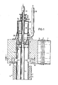
- Figure 1 is a vertical section of one embodiment of the constructive unit according to the invention, comprising the electrode support arm and the combination electrode, and Figure 2 is a cross section according to line A-A of Fig. 1.
- Figure 1 shows the end of an electrode support arm 1 on the side of the electrode.
- the electrode support arm proper 1 and its mechanisms for vertical lifting, lowering, or swivelling are of the conventional type.
- the electrode support arm 1 On the side of the electrode the electrode support arm 1 has a part 2 which is electrically insulated against the remaining part of the electrode support arm by means of an insulation 3.
- part 2 When part 2 is connected to the other part of the electrode support arm 1, this insulation 3 is inserted first. The connection is then effected by means of a flange bolt connection which is only sketched on the drawing.
- the upper metallic section 4 comprises an exterior duct 5 and a central pipe 6 coaxially arranged within the exterior duct 5.
- the metallic upper section 4 of the combination electrode is protected by a protective jacket 7.
- That part 2 of the electrode support arm 1 which is directed towards the electrode comprises a receiving element 8 with a vertical axis which has the shape of a hollow cylinder and which is open on the bottom side.
- the interior diameter of this receiving element basically corresponds to the exterior diameter of the metallic upper section 4 of the electrode, so that the upper end of the metallic section 4 of the electrode can be inserted from below into the receiving element 8 of part 2 of the electrode support arm 1.
- the receiving element and the upper section of the electrode are coordinated in such a way that a high mechanical stability is guaranteed.
- the mechanical connection or locking of the electrode to the receiving element 8 of the electrode support arm 1 is effected by a mechanical, positive fastening element.
- This element comprises a bayonet ring 9, which is located at the lower end'of the receiving element coaxially to its axis and pivoted on a bearing 10 that is only schematically illustrated.
- the bayonet ring 9 has two diametrically opposite, radial recesses 11.
- Corresponding to these recesses 11 ' of the bayonet ring ' 9 are two diametrically opposite bayonet locking elements 12 on the exterior sheath area of the metallic section 4 of the electrode.
- the locking elements When the upper end of the metallic section 4 of the electrode is inserted into the receiving element 8 of the electrode support arm 1, these locking elements can be moved through the recesses 11 of the bayonet ring 9 until they 12 lie above the bayonet ring 9, which can then be turned by e.g. 45°. The locking elements 12 of the electrode will now reach behind the bayonet ring 9, which results in a positive locking or fastening of the electrode in the electrode support arm 1.
- the bayonet ring 9 may be turned manually, pneumatically, hydraulically or by electric motor.
- the electrode support arm 1 and the upper metallic section 4 of the electrode comprise the following components.
- a bearing case 13 which has the shape of a hollow cylinder and is located coaxially to the axis of the recess.
- This bearing case 13 may be a suitable welded structure.
- the bearing case 13 contains a connection piece 14, which has basically the shape of a hollow cylinder that is coaxially and axially movable.
- the connection piece provides the connection of the electric current as well as that of the liquid coolant.
- the lower end of the connection piece 14 has a conically tapering exterior surface 15.
- a contact ring 16 At the upper end of the metallic section 4 of the electrode there is a contact ring 16 with a corresponding conical interior surface 17.
- the contact ring 16 may be welded on the exterior pipe 5 .- of the electrode.
- connection piece 14 When the electrode in the electrode support arm is in the operating position, the conical exterior surface 15 of the connection piece 14 and the conical interior surface 17 of the contact ring 16 engage under the action of a set of helical compression springs 18, which are located between a closing wall 19 of the bearing case 13 and a partition wall 20 of the connection piece 14, thus pressing the latter down. If the electrode has to be disconnected, the connection piece 14 can be somewhat lifted against the spring arrangement 18 by the action of a pneumatic cylinder 21, the piston of which 22 interacts with a supply piece 23, which, in the interior of the connection piece 14, is connected with the same in a coaxial and rigid manner.
- This supply piece 23 provides the simultaneous supply of liquid coolant and electric current.
- this central pipe 6 may be connected in alignment to the supply piece 23.
- Either the supply piece 23 or the central pipe 6 is equipped with a seal 24, which provides a liquid-proof connection of supply piece 23 and central pipe 6.
- the current is supplied via the supply piece 23 to the connection piece 14, and from there to the contact ring 16 of the electrode. From there the current is supplied via the exterior duct 5 and the central pipe 6 to the lower section of the electrode of consumable material, preferably graphite.
- the ring cavity 25 located in the electrode between the exterior duct 5 and the central pipe 6 is used for the discharge of the liquid coolant. From there the liquid coolant passes via bores 26 and a further ring cavity 27 to the lower part of the connection piece 14, which acts as a discharge piece 28, from where the liquid coolant - passes via a discharge pipe 29 to the liquid coolant source for recirculation.
- the discharge pipe 29 may also be used for the current supply, for here too the electric current may be transferred via a connection piece 14 to the contact ring 16.
- All current-carrying components consist of an electrically highly conductive material, e.g. copper.
Landscapes
- Physics & Mathematics (AREA)
- Engineering & Computer Science (AREA)
- Plasma & Fusion (AREA)
- Discharge Heating (AREA)
Applications Claiming Priority (2)
| Application Number | Priority Date | Filing Date | Title |
|---|---|---|---|
| CH2503/82 | 1982-04-23 | ||
| CH250382 | 1982-04-23 |
Publications (1)
| Publication Number | Publication Date |
|---|---|
| EP0093079A1 true EP0093079A1 (de) | 1983-11-02 |
Family
ID=4235268
Family Applications (1)
| Application Number | Title | Priority Date | Filing Date |
|---|---|---|---|
| EP83810147A Withdrawn EP0093079A1 (de) | 1982-04-23 | 1983-04-12 | Elektrodenvorrichtung für elektrische Lichtbogenöfen |
Country Status (6)
| Country | Link |
|---|---|
| US (1) | US4509178A (de) |
| EP (1) | EP0093079A1 (de) |
| JP (1) | JPS59890A (de) |
| KR (1) | KR870000734B1 (de) |
| SU (1) | SU1169546A3 (de) |
| ZA (1) | ZA832152B (de) |
Cited By (2)
| Publication number | Priority date | Publication date | Assignee | Title |
|---|---|---|---|---|
| EP0167485A1 (de) * | 1984-06-25 | 1986-01-08 | Arc Technologies Systems, Ltd. | Anordnung für den automatischen Kühlwasseranschluss an wassergekühlten Kombinationselektroden für Elektrolichtbogenöfen |
| EP0392386A2 (de) * | 1989-04-14 | 1990-10-17 | Firma Carl Zeiss | Elektrische Steckverbindung |
Families Citing this family (5)
| Publication number | Priority date | Publication date | Assignee | Title |
|---|---|---|---|---|
| GB8309469D0 (en) * | 1983-04-07 | 1983-05-11 | British Steel Corp | Connection of services between separable members |
| DE3447177A1 (de) * | 1984-11-22 | 1986-05-28 | Norddeutsche Seekabelwerke Ag, 2890 Nordenham | Verfahren und vorrichtung zur biologischen behandlung von wasser, insbesondere zur denitrifikation von rohwasser zur trinkwasseraufbereitung |
| US4802188A (en) * | 1985-09-26 | 1989-01-31 | Great Lakes Carbon Corporation | Water trap manifold for water cooled electrodes |
| SE452087B (sv) * | 1986-02-19 | 1987-11-09 | Asea Ab | Elektrod for ljusbagsugn |
| RU2488056C2 (ru) * | 2009-03-31 | 2013-07-20 | Алкоа Инк. | Держатель электрода в сборе и содержащая его печь |
Citations (6)
| Publication number | Priority date | Publication date | Assignee | Title |
|---|---|---|---|---|
| DE1139590B (de) * | 1960-01-20 | 1962-11-15 | Allegheny Ludlum Steel | Elektrodenschafthalterung |
| FR1376941A (fr) * | 1962-12-20 | 1964-10-31 | Heraeus Gmbh W C | Dispositif de support et d'amenée du courant de fusion pour électrodes fusibles |
| GB1109709A (en) * | 1966-04-01 | 1968-04-10 | Metalectric Furnaces Ltd | Electrode stub clamp |
| DE1690556A1 (de) * | 1968-01-08 | 1971-05-27 | Demag Elektrometallurgie Gmbh | Vorrichtung zum Annippeln von Elektroden,insbesondere fuer elektrische Lichtbogenoefen |
| EP0050682A1 (de) * | 1980-10-27 | 1982-05-05 | Arc Technologies Systems, Ltd. | Elektrode für Lichtbogenöfen |
| GB2087699A (en) * | 1980-11-17 | 1982-05-26 | Leybold Heraeus Gmbh & Co Kg | Graphite electrode for use in an electric furnace |
Family Cites Families (4)
| Publication number | Priority date | Publication date | Assignee | Title |
|---|---|---|---|---|
| US2600823A (en) * | 1949-01-15 | 1952-06-17 | Allegheny Ludlum Steel | Hot top electrode tip |
| US3377418A (en) * | 1967-08-28 | 1968-04-09 | Westinghouse Electric Corp | Small diameter fluid cooled arc-rotating electrode |
| US3489841A (en) * | 1968-02-26 | 1970-01-13 | Dow Chemical Co | Arc melting furnace and method of melting |
| DE2845367C2 (de) * | 1978-10-18 | 1981-01-22 | Korf & Fuchs Syst Tech | FlUssigkeitsgekühlte Halterung für die Spitze einer Elektrode eines Lichtbogenschmelzofens |
-
1983
- 1983-03-25 ZA ZA832152A patent/ZA832152B/xx unknown
- 1983-04-12 EP EP83810147A patent/EP0093079A1/de not_active Withdrawn
- 1983-04-15 KR KR1019830001587A patent/KR870000734B1/ko active IP Right Grant
- 1983-04-21 US US06/487,119 patent/US4509178A/en not_active Expired - Fee Related
- 1983-04-22 JP JP58072039A patent/JPS59890A/ja active Pending
- 1983-04-22 SU SU833585698A patent/SU1169546A3/ru active
Patent Citations (6)
| Publication number | Priority date | Publication date | Assignee | Title |
|---|---|---|---|---|
| DE1139590B (de) * | 1960-01-20 | 1962-11-15 | Allegheny Ludlum Steel | Elektrodenschafthalterung |
| FR1376941A (fr) * | 1962-12-20 | 1964-10-31 | Heraeus Gmbh W C | Dispositif de support et d'amenée du courant de fusion pour électrodes fusibles |
| GB1109709A (en) * | 1966-04-01 | 1968-04-10 | Metalectric Furnaces Ltd | Electrode stub clamp |
| DE1690556A1 (de) * | 1968-01-08 | 1971-05-27 | Demag Elektrometallurgie Gmbh | Vorrichtung zum Annippeln von Elektroden,insbesondere fuer elektrische Lichtbogenoefen |
| EP0050682A1 (de) * | 1980-10-27 | 1982-05-05 | Arc Technologies Systems, Ltd. | Elektrode für Lichtbogenöfen |
| GB2087699A (en) * | 1980-11-17 | 1982-05-26 | Leybold Heraeus Gmbh & Co Kg | Graphite electrode for use in an electric furnace |
Cited By (4)
| Publication number | Priority date | Publication date | Assignee | Title |
|---|---|---|---|---|
| EP0167485A1 (de) * | 1984-06-25 | 1986-01-08 | Arc Technologies Systems, Ltd. | Anordnung für den automatischen Kühlwasseranschluss an wassergekühlten Kombinationselektroden für Elektrolichtbogenöfen |
| EP0392386A2 (de) * | 1989-04-14 | 1990-10-17 | Firma Carl Zeiss | Elektrische Steckverbindung |
| EP0392386A3 (de) * | 1989-04-14 | 1991-03-20 | Firma Carl Zeiss | Elektrische Steckverbindung |
| US5015202A (en) * | 1989-04-14 | 1991-05-14 | Carl-Zeiss-Stiftung | Electric plug connector |
Also Published As
| Publication number | Publication date |
|---|---|
| KR870000734B1 (ko) | 1987-04-09 |
| JPS59890A (ja) | 1984-01-06 |
| US4509178A (en) | 1985-04-02 |
| SU1169546A3 (ru) | 1985-07-23 |
| KR840004657A (ko) | 1984-10-22 |
| ZA832152B (en) | 1983-12-28 |
Similar Documents
| Publication | Publication Date | Title |
|---|---|---|
| EP0093079A1 (de) | Elektrodenvorrichtung für elektrische Lichtbogenöfen | |
| CA1169457A (en) | Heavy-current conduction system for electric furnaces | |
| US4125737A (en) | Electric arc furnace hearth connection | |
| KR20140050727A (ko) | 전기 유도 용해 어셈블리 | |
| US5378870A (en) | Power block for liquid-cooled power cables | |
| US3761379A (en) | Aluminum production apparatus | |
| WO1993007986A1 (en) | Swivel coupling | |
| ZA907468B (en) | Anode for direct current arc furnace | |
| US4424584A (en) | Electrode holder assembly for self-baking electrodes | |
| SU1093266A3 (ru) | Держатель электрода дуговой электропечи | |
| US4492423A (en) | Rotatable heavy-current connector | |
| US4417345A (en) | Holder for an electrode | |
| Curr et al. | The design and operation of transferred-arc plasma systems for pyrometallurgical applications | |
| JP3288431B2 (ja) | 高電流供給部を切り換えるための装置 | |
| US4204082A (en) | DC Arc furnace having starting electrode | |
| US4672628A (en) | Assembly for the automatic cooling water connection to water-cooled combination electrodes for electric arc furnaces | |
| EP0135473A1 (de) | Elektrodenvorrichtung für Lichtbogenöfen | |
| US4446561A (en) | Axially movable electrode holder for use in electric steel production | |
| US4458352A (en) | Method and device providing mobility to a contact shoe independent of an electrode in an electric-arc furnace | |
| US4170712A (en) | Tiltable arc furnace | |
| US3311693A (en) | Device for suspending a consumable electrode and supplying a melting current thereto | |
| JPH04217783A (ja) | 炉底電極を備えた直流電気炉 | |
| JP2832539B2 (ja) | 金属融成物の熱処理装置 | |
| CA1167500A (en) | Holder assembly for an electrode in an electrothermal smelting furnace | |
| CA2035931A1 (fr) | Recipient metallurgique equipe d'au moins une electrode traversant sa paroi |
Legal Events
| Date | Code | Title | Description |
|---|---|---|---|
| PUAI | Public reference made under article 153(3) epc to a published international application that has entered the european phase |
Free format text: ORIGINAL CODE: 0009012 |
|
| AK | Designated contracting states |
Designated state(s): AT BE CH DE FR GB IT LI LU NL SE |
|
| 17P | Request for examination filed |
Effective date: 19840324 |
|
| 17Q | First examination report despatched |
Effective date: 19860506 |
|
| STAA | Information on the status of an ep patent application or granted ep patent |
Free format text: STATUS: THE APPLICATION IS DEEMED TO BE WITHDRAWN |
|
| 18D | Application deemed to be withdrawn |
Effective date: 19861031 |
|
| RIN1 | Information on inventor provided before grant (corrected) |
Inventor name: FINK, FRIEDRICH Inventor name: LADES, HANS Inventor name: LAUTERBACH, INGE, DR. Inventor name: ZOELLNER, DIETER, DR. Inventor name: LIEBEL, SIEGFRIED Inventor name: TAUBE, THOMAS, DR. |