EP0091844A1 - Sealing ring placed between an apparatus and a screw joint for high-pressure pipelines - Google Patents
Sealing ring placed between an apparatus and a screw joint for high-pressure pipelines Download PDFInfo
- Publication number
- EP0091844A1 EP0091844A1 EP83400543A EP83400543A EP0091844A1 EP 0091844 A1 EP0091844 A1 EP 0091844A1 EP 83400543 A EP83400543 A EP 83400543A EP 83400543 A EP83400543 A EP 83400543A EP 0091844 A1 EP0091844 A1 EP 0091844A1
- Authority
- EP
- European Patent Office
- Prior art keywords
- hoop
- ring
- sealing member
- seal
- seal according
- Prior art date
- Legal status (The legal status is an assumption and is not a legal conclusion. Google has not performed a legal analysis and makes no representation as to the accuracy of the status listed.)
- Granted
Links
Images


Classifications
-
- F—MECHANICAL ENGINEERING; LIGHTING; HEATING; WEAPONS; BLASTING
- F16—ENGINEERING ELEMENTS AND UNITS; GENERAL MEASURES FOR PRODUCING AND MAINTAINING EFFECTIVE FUNCTIONING OF MACHINES OR INSTALLATIONS; THERMAL INSULATION IN GENERAL
- F16L—PIPES; JOINTS OR FITTINGS FOR PIPES; SUPPORTS FOR PIPES, CABLES OR PROTECTIVE TUBING; MEANS FOR THERMAL INSULATION IN GENERAL
- F16L15/00—Screw-threaded joints; Forms of screw-threads for such joints
- F16L15/001—Screw-threaded joints; Forms of screw-threads for such joints with conical threads
- F16L15/003—Screw-threaded joints; Forms of screw-threads for such joints with conical threads with sealing rings
-
- F—MECHANICAL ENGINEERING; LIGHTING; HEATING; WEAPONS; BLASTING
- F16—ENGINEERING ELEMENTS AND UNITS; GENERAL MEASURES FOR PRODUCING AND MAINTAINING EFFECTIVE FUNCTIONING OF MACHINES OR INSTALLATIONS; THERMAL INSULATION IN GENERAL
- F16L—PIPES; JOINTS OR FITTINGS FOR PIPES; SUPPORTS FOR PIPES, CABLES OR PROTECTIVE TUBING; MEANS FOR THERMAL INSULATION IN GENERAL
- F16L15/00—Screw-threaded joints; Forms of screw-threads for such joints
- F16L15/006—Screw-threaded joints; Forms of screw-threads for such joints with straight threads
- F16L15/008—Screw-threaded joints; Forms of screw-threads for such joints with straight threads with sealing rings
-
- F—MECHANICAL ENGINEERING; LIGHTING; HEATING; WEAPONS; BLASTING
- F16—ENGINEERING ELEMENTS AND UNITS; GENERAL MEASURES FOR PRODUCING AND MAINTAINING EFFECTIVE FUNCTIONING OF MACHINES OR INSTALLATIONS; THERMAL INSULATION IN GENERAL
- F16L—PIPES; JOINTS OR FITTINGS FOR PIPES; SUPPORTS FOR PIPES, CABLES OR PROTECTIVE TUBING; MEANS FOR THERMAL INSULATION IN GENERAL
- F16L41/00—Branching pipes; Joining pipes to walls
- F16L41/007—Branching pipes; Joining pipes to walls adjustable and comprising a bend
Abstract
Joint d'étanchéité disposé entre un raccord pour tuyauterie de fluide à haute pression et un appareil présentant un trou taraudé dans lequel est vissée la partie filetée du raccord. Le joint d'étanchéité comprend une frette (14) en matériau dur et résistant en appui par l'une de ses deux faces contre la paroi (6b) de l'appareil (6) et présentant un alésage (14a, 14b) dans lequel sont engagés autour du raccord (2) un organe d'étanchéité (13) en matériau fluable et malléable et une bague à sertir (12) en matériau ductile présentant un section la forme d'un coin, ladite bague (12) étant sertie à l'intérieur de la frette (14) lors du visage du raccord. L'invention est utilisée pour l'étanchéité des raccords vissés sur un appareil.A seal placed between a fitting for high pressure fluid piping and an apparatus having a tapped hole into which the threaded portion of the fitting is screwed. The seal comprises a hoop (14) made of hard and resistant material resting on one of its two faces against the wall (6b) of the device (6) and having a bore (14a, 14b) in which are engaged around the connector (2) a sealing member (13) of flowable and malleable material and a crimp ring (12) of ductile material having a cross section in the form of a wedge, said ring (12) being crimped the inside of the hoop (14) during the face of the fitting. The invention is used for sealing screw connections on an appliance.
Description
La présente invention a pour objet un joint d'étanchéité disposé entre un raccord et l'appareil sur lequel est vissé le raccord, notamment pour les circuits de fluide en général et en particulier pour les circuits d'asservissement hydraulique à haute pression.The present invention relates to a seal arranged between a connector and the device on which the connector is screwed, in particular for fluid circuits in general and in particular for high pressure hydraulic control circuits.
Les raccords pour fluide hydraulique à haute pression sont toujours vissés sur les appareils et malgré les recherches effectuées dans ce domaine l'étanchéité des organes vissés n'a pu être maîtrisée de telle sorte que les fuites de liquide présentent de graves inconvénients tant sur le plan pécuniaire,que sur le plan des dégâts occasionnés par lesdites fuites. On a pu constater que la moitié des fuites des installations d'asservissement hydraulique est imputable à l'implantation par vissage des raccords. Toutes les grandes entreprises et en particulier celles de l'industrie automobile rencontrent cette difficulté et remettent en question l'utilisation de l'asservissement hydraulique qui pourtant est très important. Pour une seule entreprise les fuites de liquide peuvent atteindre près de deux millions de litres d'huile qui doivent être remplacés et dont le prix est de plus en plus élevé.The fittings for high pressure hydraulic fluid are always screwed onto the devices and despite the research carried out in this field, the tightness of the screwed members has not been controlled so that the leaks of liquid have serious drawbacks both in terms of pecuniary, only in terms of damage caused by said leaks. It has been observed that half of the leaks in the hydraulic servo systems are attributable to the installation by screwing of the fittings. All the big companies and in particular those of the automobile industry meet this difficulty and question the use of the hydraulic servo which however is very important. For a single company, liquid leaks can reach almost two million liters of oil which must be replaced and the price of which is higher and higher.
Par ailleurs tous les liquides de coupe pour l'usinage doivent être souvent remplacés, car ils sont pollués par ces fuites d'huile. Enfin les planchers en béton des bâtiments sont dégradés par l'huile qui est répandue sur ceux-ci et ils ne supportent plus la charge des chaînes de montage ou d'usinage; en conséquence, il est nécessaire dans certains cas de les démolir et de les reconstruire. Pour prévenir ces inconvénients, il est prévu un personnel de nettoyage et d'entretien qui assure le nettoyage du sol, le nettoyage et la vidange des bacs de liquide de coupe des machines d'usinage et le resserrage des raccords pour supprimer autant qu'il est possible les fuites de liquide. Toutefois, ces fuites sont très difficiles à déceler du fait qu'il s'agit d'un suintement goutte à goutte.In addition, all cutting fluids for machining must be replaced often, as they are polluted by these oil leaks. Finally, the concrete floors of buildings are degraded by the oil which is spilled on them and they no longer support the load of assembly or machining chains; consequently, it is necessary in some cases to demolish and rebuild them. To prevent these drawbacks, a cleaning and maintenance staff is provided who cleans the floor, cleans and empties the cutting fluid tanks of the machining machines and tightens the fittings to remove as much as possible. liquid leakage is possible. However, these leaks are very difficult to detect because it is a dripping oozing.
Les pressions élevées et surtout les cycles très rapides des machines actuelles, ainsi que les vibrations,.communiquent des à-coups de pression très violents qui ébranlent les implantations vissées des raccords en créant des micromatages des parties métalliques en contact, ainsi que des microjeux, donnant passage à des suintements d'huile très pernicieux. La cause de ces fuites d'huile réside dans le fait que les joints d'étanchéité ne permettent pas d'obtenir une étanchéité absolue des implantations vissées de raccords.The high pressures and especially the very rapid cycles of current machines, as well as the vibrations, communicate very violent pressure surges which shake the screwed implantations of the fittings by creating micromatations of the metallic parts in contact, as well as micro-games, giving way to very pernicious oil seeps. The cause of these oil leaks lies in the fact that the seals do not make it possible to obtain absolute tightness of the screwed implantations of fittings.
Un tel joint d'étanchéité doit répondre aux conditions d'utilisation mentionnées ci-après.Such a seal must meet the conditions of use mentioned below.
Le raccord vissé avec son joint doit être étanche de la pression nulle à une pression d'épreuve de 600 bars. Les joints doivent pouvoir être étanches avec le maximum de formes de raccords et d'implantations vissées existantes. Le joint doit supporter des imperfections d'usinage de l'implantation à vis et comprenser les imperfections. Le joint doit pouvoir supporter sans détérioration quatre ou cinq démontages et remontages du raccord sur l'appareil. Le joint doit pouvoir résister à une température de 100°C en continu. La pression de service du circuit hydraulique est comprise entre 0 et 400 bars. Les joints doivent résister aux fluides d'asservissement hydraulique tels que les produits pétroliers, un mélange d'eau et de glycol, et également aux fluides ininflammables du commerce. La durée de l'étanchéité doit correspondre à environ 20 000 heures de machine ou dix ans dlgge et à environ cinq millions de cycles.The screw connection with its seal must be tight from zero pressure to a test pressure of 600 bars. The joints must be able to be watertight with the maximum number of existing screw fittings and layouts. The joint must withstand imperfections in the machining of the screw implantation and compress the imperfections. The seal must be able to withstand four or five disassembly and reassembly of the fitting on the device without deterioration. The joint must be able to withstand a temperature of 100 ° C continuously. The operating pressure of the hydraulic circuit is between 0 and 400 bar. The seals must resist hydraulic servo fluids such as petroleum products, a mixture of water and glycol, and also non-flammable commercial fluids. The duration of the seal should be approximately 20,000 machine hours or ten years of age lg and about five million cycles.
Le montage doit s'effectuer avec un personnel non spécialisé dont la période d'adaptation est de quelques heures seulement.Assembly must be carried out by non-specialized personnel whose adaptation period is only a few hours.
Le joint d'étanchéité suivant l'invention est un joint universel qui est capable d'assurer l'étanchéité de nombreux types d'implantations vissées de raccords.The seal according to the invention is a universal seal which is capable of sealing many types of screwed implantations of fittings.
Les difficultés qui ont été mentionnées ci-dessus pour obtenir une étanchéité totale ont donné naissance à de nombreuses implantations de raccords, mais pratiquement sans aucun succès. Ils ne sont étanches que si toutes les conditions de qualité maximale d'usinage sont réunies ce qui dans le meilleur des cas ne saurait dépasser dans ces fabrications entre 80 à 90%. Il y a donc lieu de compter sur au moins 20 à 10% d'implantations de raccord présentant des fuites.The difficulties which have been mentioned above in order to obtain a total seal have given rise to numerous implantations of fittings, but practically without any success. They are only waterproof if all the conditions for maximum machining quality are met, which in the best of cases cannot exceed between 80 and 90% in these products. It is therefore necessary to count on at least 20 to 10% of fittings with leaks.
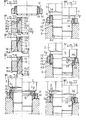
A la figure 1, on a représenté un raccord 1 dont la partie cylindrique filetée la est vissée dans un trou taraudé cylindrique 6a du corps 6 d'un appareil. Un joint torique lb en caoutchouc est disposé dans un logement annulaire lc du raccord 1. Lorsque l'usinage est parfait, le dispositif est étanche, car le joint est bien enfermé. Toutefois, ce dispositif ne supporte pas le faux équerrage de la face 6b (extrusion du joint par l'espace laissé libre par le jeu), un mauvais état de la surface 6b, notamment de petites rayures qui occasionnent des suintements, les fluides inadaptés au caoutchouc, les températures supérieures à 100°C.In Figure 1, there is shown a
A la figure 2, on a représenté un raccord 2 dont la partie cylindrique filetée 2a est vissée dans un trou cylindrique taraudé 6a, et un joint en cuivre 7 est maintenu serré à plat entre le raccord 2 et le logement plat 6b. Ce dispositif simple ne supporte pas un faux équerrage qui provoque une fuite, un état de suface trop grossier de la face 6b, un lamage 6b différent du diamètre extérieur du joint, une absence de lamage. Le joint en cuivre doit être maintenu par son diamètre extérieur pour résister à la pression.In Figure 2, there is shown a
A la figure 3, on a représenté un raccord 3 dont la partie cylindrique filetée 3a est vissée dans un trou taraudé 6a. Le raccord comporte une arête périphérique 3b qui constitue une portée métallique d'étanchéité sur la face 6b. Ce dispositif ne tolère aucun faux équerrage de la face 6b (même léger) sans risque de fuites, un mauvais état de la surface 6b, des coups ou marques sur l'arête 3b.In Figure 3, there is shown a
A la figure 4, on a représenté un raccord 4 dont la partie filetée conique 4a est vissée avec un serrage radial dans un trou taraudé cylindrique 8a. L'étanchéité est obtenue au moyen d'un joint fin constitué d'un ruban en matière plastique placé entre le filetage et le taraudage ou bien à l'aide d'une colle constituant un joint spécial. La matière plastique ne tient pas et elle est extrudée par les pressions élevées. Enfin, la colle spéciale n'est pas totalement efficace, car sa répartition sur le filetage n'est pas égale sur tout le pourtour.In Figure 4, there is shown a
A la figure 5, on a représenté un raccord 5 présentant une partie filetée conique 5a qui est vissée dans un trou taraudé conique 9a. L'étanchéité est obtenue au moyen d'un ruban fin en matière plastique disposé entre le filetage et le taraudage, au moyen d'une colle ou sans moyen intermédiaire, mais toujours avec un très fort serrage. Cependant, les appareils ne résistent pas toujours à un tel serrage et se fendent quelquefois. A la figure 6, on a représenté un raccord 10 présentant une partie filetée cylindrique 10a qui est vissée dans un trou taraudé cylindrique lla, l'étanchéité étant réalisée par un joint torique 10b en caoutchouc emprisonné entre une gorge du raccord et une partie conique llb de l'appareil 11. Ce dispositif ne supporte pas le faux équerrage de la face lld, un mauvais état de surface (rayures) de la partie conique llb, les fluides inadaptés au caoutchouc, les trop fortes pressions et les températures supérieures à 100°C.In Figure 5, there is shown a
A la figure 7, on a représenté un raccord dont le montage est identique à celui de la figure 2, seul le joint étant différent. Dans ce cas, le joint est composite et il comprend une rondelle en acier sur lequelle est adhérisé dans son alésage un joint en caoutchouc dont les lèvres sont en appui sur le raccord et sur la face 6b. Ces joints sont bien connus en hydraulique; mais ce dispositif ne supporte pas un faux équerrage de la face 6b, un mauvais état de surface (rayures) de la face 6b, les pressions élevées, les fluides non adaptés au caoutchouc et les températures supérieures à 100°C.In Figure 7, there is shown a connector whose mounting is identical to that of Figure 2, only the seal being different. In this case, the seal is composite and it includes a steel washer on which is adhered in its bore a rubber seal whose lips are supported on the connector and on the
A la figure 8, on a représenté un raccord identique à celui de la figure 2, dans lequel seul le joint est différent. Dans ce cas, le joint présente une double arête couteau 2d qui est en acier dur traité et s'incruste au serrage dans les faces d'appui du raccord et de la face 6b. Cette bague coupante ne supporte pas un faux équerrage de la face 6b assez important, le démontage et le remontage du joint,car il est pratiquement impossible de remettre, lors du vissage, les arêtes coupantes dans leurs premières empreintes et il en résulte des fuites.In Figure 8, there is shown a fitting identical to that of Figure 2, in which only the seal is different. In this case, the joint has a
A la figure 9, on a représenté un raccord et un trou taraudé cylindrique identiques à la figure 2. Seul le joint est différent et il comprend une coupelle en acier 2e, garnie d'un joint en caoutchouc 2f. Théoriquement le joint en caoutchouc remplit complètement et seulement la coupelle, mais,en réalité, il est impossible d'obtenir un volume de caoutchouc exactement suffisant. Dans le cas où le volume de caoutchouc est insuffisant, la coupelle n'est pas pleine et il se produit une fuite. Dans l'autre cas, il y a trop de caoutchouc et la coupelle ne peut emprisonner tout le joint qui soulève la coupelle et s'extrude en produisant des fuites.In Figure 9, there is shown a fitting and a cylindrical threaded hole identical to Figure 2. Only the seal is different and it includes a
Les dispositifs correspondant aux figures 1 à 8, qui sont les plus utilisés, ne permettent donc pas d'obtenir une étanchéité réellement sure et ils présentent tous des défauts importants. Avec ces dispositifs d'étanchéité, il faut comprendre que, même si les usinages et les lamages des faces ont été effectués avec beaucoup de soin, avec des mèches de forme, il n'en demeure pas moins que le taraudage,qui est effectué souvent en reprise, est souvent de travers et présente un faux équerrage avec les faces d'appui des appareils. En réalité, c'est l'opération de taraudage qui entraîne de graves défauts et aussi les coups et rayures sur les pièces usinées pendant les manipulations et le transport.The devices corresponding to FIGS. 1 to 8, which are the most used, therefore do not make it possible to obtain a truly secure seal and they all have significant defects. With these sealing devices, it should be understood that, even if the machining and the countersinking of the faces were carried out with great care, with shaped bits, the fact remains that the tapping, which is carried out often in recovery, is often askew and has a false squaring with the bearing faces of the devices. In reality, it is the tapping operation which causes serious faults and also knocks and scratches on the machined parts during handling and transport.
Le joint d'étanchéité suivant l'invention a pour but d'obtenir une étanchéité parfaite, durable, pour des fluides à haute pression, malgré la présence de défauts de surface ou d'équerrage pour les dispositifs de raccord et d'implantation par trou taraudé représentés sur les figures 1 à 9.The purpose of the seal according to the invention is to obtain a perfect, durable seal for high-pressure fluids, despite the presence of surface or squaring defects for the connection and implantation devices by hole. tapped shown in Figures 1 to 9.
Conformément à la présente invention le joint d'étanchéité comprend une frette 14, 17, 20 en matériau dur et résistant en appui par l'une de ses deux faces contre la paroi 6b de l'appareil 6 et présentant un alésage 14a, 14b, 17a, 17b, 20b dans lequel sont engagés autour du raccord 2 un organe d'étanchéité 13, 16, 19 en matériau fluable et malléable et une bague à sertir 12, 15, 18 en matériau ductile présentant en section la forme d'un coin, ladite bague 12, 15, 18 étant sertie à l'intérieur de la frette 14, 17, 20 lors du vissage du raccord, de manière à constituer une enceinte annulaire étanche à volume variable dans laquelle est comprimé l'organe d'étancnéité 13, 16, 19 qui remplit par fluage ledit espace annulaire pendant l'opération de vissage du raccord, ladite enceinte annulaire étant délimitée par le raccord 2, la bague sertie 12, 15, 18, la frette 14, 17, 20 et la face de l'appareil 6 dont les points de contact constituent des moyens antiextrusion de l'organe d'étanchéité 13, 16, 19, ladite frette et ladite bague à sertir étant solidarisées par des moyens ménagés sur le joint d'étanchéité.In accordance with the present invention, the seal comprises a
La caractéristique principale du joint d'étanchéité suivant l'invention réside dans le fait qu'il présente un ensemble d'une hauteur beaucoup plus importante que les joints classiques, et qu'il forme,avec le raccord et la face avant du trou taraudé, une enceinte fermée par des points de contact constituant des moyens d'antiextrusion permanents. Le volume variable de cette enceinte étant réduit lors du vissage du raccord jusqu'à ce que l'organe d'étanchéité fluable ait entièrement rempli par fluage sous haute pression ladite enceinte.The main characteristic of the seal according to the invention resides in the fact that it has an assembly of a height much greater than the conventional seals, and that it forms, with the connector and the front face of the tapped hole. , an enclosure closed by contact points constituting permanent anti-extrusion means. The variable volume of this enclosure being reduced when the fitting is screwed until the flowable sealing member has completely filled by creep under high pressure said enclosure.
La matière fluable de l'organe d'étanchéité remplit tous les interstices de l'enceinte fermée, les jeux du filetage, les défauts, les rayures, les gorges, les chanfreins et les logements. Le raccord vient en position de blocage à la fin de la compression de la matière fluable constituant l'organe d'étanchéité dans l'enceinte annulaire.The flowable material of the sealing member fills all the interstices of the closed enclosure, the clearance of the thread, the defects, the scratches, the grooves, the chamfers and the housings. The connector comes into the locking position at the end of the compression of the flowable material constituting the sealing member in the annular enclosure.
Le dispositif suivant l'invention est auto-étanche, du fait que le fluide sous pression qui arrive par le filetage ne peut que surcomprimer l'organe d'étanchéité dans son enceinte et augmenter l'étanchéité. Ce dispositif qui compense tous les défauts de surface et d'équerrage est antivibratoire et son freinage empêche le raccord de se dévisser même avec de fortes vibrations.The device according to the invention is self-sealing, because the pressurized fluid which arrives by the thread can only overpress the sealing member in its enclosure and increase the sealing. This device, which compensates for all surface and squaring faults, is anti-vibration and its braking prevents the fitting from unscrewing even with strong vibrations.
Enfin, le joint d'étanchéité suivant l'invention peut être démonté et remonté plusieurs fois.Finally, the seal according to the invention can be dismantled and reassembled several times.
Les organes d'étanchéité sont constitués de matières qui conviennent à tous les produits utilisés pour l'asservissement hydraulique et qui permettent une utilisation pendant de nombreuses années et au moins la durée d'une machine moderne.The sealing members are made of materials which are suitable for all products used for hydraulic servo-control and which allow use for many years and at least the duration of a modern machine.
Ces joints sont utilisables pour des pressions comprises entre 0 et 400 bars et leur montage avec une enceinte fermée ne subit pas le classique phénomène de pompage dû aux cycles de pression et à l'usure qui résulte de ce phénomène.These seals can be used for pressures between 0 and 400 bars and their mounting with a closed enclosure does not undergo the conventional pumping phenomenon due to the pressure cycles and to the wear which results from this phenomenon.
La résistance de l'organe d'étanchéité à une température de 100°C ne pose aucun problème et il est possible d'aller au-delà avec des matières appropriées.The resistance of the sealing member to a temperature of 100 ° C. poses no problem and it is possible to go beyond it with suitable materials.
Ces joints ne présentent aucune difficulté de montage du fait qu'il suffit de les engager par leur petit diamètre sur le corps du raccord qui est vissé dans le trou taraudé. Ces joints sont vraiment universels du fait qu'ils peuvent assurer l'étanchéité des raccords vissés les plus utilisés.These seals do not present any difficulty in mounting since it suffices to engage them by their small diameter on the body of the connector which is screwed into the tapped hole. These seals are really universal because they can seal the most used screw fittings.
D'autres caractéristiques et avantages de l'invention seront mieux compris à la lecture de la description qui va suivre de plusieurs modes de réalisation et en se référant aux dessins annexés, sur lesquels :Other characteristics and advantages of the invention will be better understood on reading the following description of several embodiments and with reference to the appended drawings, in which:
- Les figures 1 à 9 sont des vues en élévation et en coupe du montage de raccords vissés sur des appareils avec des moyens d'étanchéité de type connu.Figures 1 to 9 are views in elevation and in section of the mounting of screw connections on devices with sealing means of known type.
- La figure 10 est une vue en élévation et en coupe axiale d'un mode de réalisation d'un joint d'étanchéité suivant l'invention.Figure 10 is an elevational view in axial section of an embodiment of a seal according to the invention.
- La figure 11 est une vue en élévation et en coupe du joint d'étanchéité précédent monté avant et après serrage sur un raccord.Figure 11 is an elevational and sectional view of the previous seal mounted before and after tightening on a fitting.
- La figure 12 est une demi-vue en coupe à plus grande échelle du raccord représenté à la figure 10.FIG. 12 is a half-view in section on a larger scale of the connector shown in FIG. 10.
- La figure 13 est une demi-vue en coupe d'une variante de réalisation du raccord représenté à la figure 12.FIG. 13 is a half-view in section of an alternative embodiment of the connector shown in FIG. 12.
- La figure 14 est une vue en élévation et coupe d u montage avant et après serrage d'un joint d'étanchéité s:,r un raccord.Figure 14 is an elevational and sectional view of the mounting before and after tightening of a seal on a connection.
- La figure 15 est une demi-vue en coupe à échelle agrandie du joint d'étanchéité représenté à la figure 14.FIG. 15 is a half-view in section on an enlarged scale of the seal shown in FIG. 14.
- Les figures 16 à 19 sont des vues en élévation et en coupe d'un joint d'étanchéité suivant l'invention monté sur différents types de raccord.Figures 16 to 19 are views in elevation and in section of a seal according to the invention mounted on different types of connector.
- La figure 20 est une vue en élévation et en coupe d'un raccord muni d'un autre mode de réalisation d'un joint d'étanchéité.Figure 20 is an elevational and sectional view of a connector provided with another embodiment of a seal.
- La figure 21 est une demi-vue en coupe à échelle agrandie du joint d'étanchéité représenté à la figure 20.FIG. 21 is a half-view in section on an enlarged scale of the seal shown in FIG. 20.
- La figure 22 est une demi-vue en coupe d'un autre mode de réalisation d'un joint d'étanchéité.Figure 22 is a half sectional view of another embodiment of a seal.
- La figure 23 est une vue en élévation et en coupe du joint d'étanchéité de la figure 22 monté sur un raccord.Figure 23 is an elevational and sectional view of the seal of Figure 22 mounted on a connector.
- La figure 24 est une vue en élévation et en coupe du montage d'un autre mode de réalisation de joint d'étanchéité sur un raccord.Figure 24 is an elevational and sectional view of the mounting of another embodiment of a seal on a connector.
- La figure 25 est une demi-vue en coupe à échelle agrandie du joint d'étanchéité représenté à la figure 24.FIG. 25 is a half-view in section on an enlarged scale of the seal shown in FIG. 24.
- La figure 26 est une vue en élévation et en coupe du montage d'un autre mode de réalisation d'un joint d'étanchéité sur un raccord.Figure 26 is an elevational and sectional view of the mounting of another embodiment of a seal on a connector.
- La figure 27 est une demi-vue en coupe à échelle agrandie du joint d'étanchéité représenté à la figure 26.FIG. 27 is a half-view in section on an enlarged scale of the seal shown in FIG. 26.
- La figure 28 est une vue en élévation et en coupe du montage d'un joint d'étanchéité sur un appareil présentant une face en faux équerre.Figure 28 is an elevational and sectional view of the mounting of a seal on an apparatus having a false angle face.
- La figure 29 est une demi-vue d'un autre mode de réalisation d'un joint d'étanchéité.Figure 29 is a half view of another embodiment of a seal.
A la figure 10 on a représenté un joint d'étanchéité suivant l'invention prêt à l'emploi. Ce joint comprend une frette 14 constituée par une bague en acier de section importante et ayant subi un traitement pour en augmenter la résistance aux efforts, une bague 12 de faible section en métal malléable notamment en acier recuit et destinée à être sertie dans la frette 14, un organe d'étanchéité 13 en matière plastique malléable et déformable, mais non molle. L'organe d'étanchéité peut être réalisé en toute autre matière possédant les mêmes qualités, telle que des métaux mous, etc, pouvant allier la ténacité, la déformabilité et la fluabilité. Ces trois éléments sont solidaires, la frette 14 et la bague à sertir 12 étant reliées par l'organe d'étanchéité 13.In Figure 10 there is shown a seal according to the invention ready for use. This seal comprises a
Aux figures 11 et 12 on a représenté plus en détail le joint d'étanchéité dont la frette 14 comporte un alésage qui présente à l'entrée de la bague 12 une partie cylindrique 14a prolongée par une partie conique 14b et une nervure 14c délimitant du côté opposé à l'entrée une rainure circulaire.In Figures 11 and 12 there is shown in more detail the seal whose
Dans la partie cylindrique 14a de l'alésage de la frette 14 est disposée la bague 12 à sertir qui présente en section la forme d'un coin et comporte une surface extérieure cylindrique 12a coopérant avec l'alésage de la frette et une surface intérieure sphérique concave 12£, ladite bague étant montée dans l'alésage de la frette jusqu'à la partie conique 14b. L'organe d'étanchéité 13 est disposé à l'intérieur de l'alésage de la frette et il maintient serré contre cette dernière la bague 12, de telle sorte que la partie sphérique 13b de l'organe d'étanchéité épouse la surface sphérique 12c de la bague et que des nervures périphériques 13a et 13d de l'organe d'étanchéité 13 sont engagées dans des logements correspondants de la frette 14 et de la bague 12. Cette disposition permet un encliquetage de la frette 14 et de la bague 12 sur l'organe d'étanchéité 13 de manière à constituer un ensemble manipulable présentant un alésage cylindrique 13c ménagé dans l'organe d'étanchéité.In the
Du côté opposé à la bague 12, l'organe d'étanchéité 13 présente de fines lèvres circulaires 13g qui empêchent le montage à l'envers sur la partie filetée 2a du raccord, lesdites lèvres 13g qui s'engagent aisément dans le filetage du raccord 2 empêchent le glissement du joint d'étanchéité et rendent ce dernier imperdable.On the side opposite to the
A la figure 11, on a représenté sur la demi-vue de gauche un joint d'étanchéité monté en début de serrage sur la partie filetée 2a d'un raccord 2 comportant un corps à face plate et dont la partie filetée est vissée dans un trou taraudé 6a d'un appareil 6.In Figure 11, there is shown in the left half-view a seal mounted at the start of tightening on the threaded
Dans cette disposition il est visible que le corps de raccord 2, la bague 12, la frette 14, la face avant 6b du trou taraudé 6a de l'appareil, la partie filetée 2a délimitent une enceinte annulaire fermée renfermant l'organe d'étanchéité 13.In this arrangement it is visible that the connecting
Lorsqu'on procède au serrage du raccord 2 par vissage de la partie filetée 2a dans le trou taraudé 6a, la force de serrage est transmise à la face radiale de la bague 12 par le corps 2, ladite bague,étant chassée dans la partie conique 14b de la frette, se trouve sertie radialement en comprimant l'organe d'étanchéité 13 dans l'espace annulaire fermé défini ci-dessus, comme représenté sur la partie droite de la figure 11 qui représente le joint en fin de serrage. La pénétration axiale et le sertissage radial de la bague 12 produisent une importante réduction du volume de l'espace annulaire dans lequel est enfermé l'organe d'étanchéité 13 qui par déformation fluo-plastique à haute pression remplit l'enceinte jusque dans ses moindres logements.When the
Pendant toute la période de vissage et de déformation de l'organe d'étanchéité, on réalise trois points de contact sous une très grande pression qui permettent de réaliser trois moyens d'antiextrusion de l'organe d'étanchéité.During the entire period of screwing and deformation of the sealing member, three contact points are produced under very high pressure which make it possible to produce three means of anti-extrusion of the sealing member.
L'un de ces moyens antiextrusion est obtenu lors du sertissage de la bague 12 où il se produit une tension importante entre la bague et la face d'appui du raccord 2, réalisant ainsi un contact sous haute pression entre la bague 12 et le corps 2 empêchant l'extrusion de l'organe d'étanchéité 13. Ce contact entre la bague et le corps se produit pendant toute la course de vissage et il est maintenu lors du blocage total.One of these anti-extrusion means is obtained during the crimping of the
Un autre moyen antiextrusion est obtenu par l'effort de sertissage de la bague 12 dans la partie conique 14b de la frette 14 qui provoque une force résultante appliquant la frette 14 sur la face 6b ce qui réalise un point de contact empêchant l'extrusion de l'organe d'étanchéité 13 entre la frette 14 et l'appareil 6.Another anti-extrusion means is obtained by the crimping force of the
Enfin un autre moyen antiextrusion est obtenu par la grande résistance au sertissage radial de la bague 12 (figure 11) dans la frette 14, le long de la partie conique 14b qui réalise un contact sous une pression importante entre la frette 14 et la bague 12 et empêche l'extrusion de l'organe d'étanchéité 13 entre ces deux éléments. Lors du serrage total du raccord 2 la collerette cylindrique 2g (figure 11) pénètre à l'intérieur de la frette 14, ce qui augmente la course de vissage et la réduction de l'enceinte annulaire renfermant l'organe d'étanchéité.Finally, another anti-extrusion means is obtained by the high resistance to radial crimping of the ring 12 (FIG. 11) in the
A la figure 13, on a représenté un autre mode de réalisation du joint d'étanchéité dans lequel on utilise des nervures 13e sur le joint 13 et 14d sur la frette qui assurent un encliquetage indémontable et irréversible du joint 13 sur la frette 14 et la bague 12.In FIG. 13, another embodiment of the seal has been shown in which
Aux figures 14 et 15 on a représenté une variante de réalisation du joint d'étanchéité représenté aux figures 11 et 12, dans laquelle il est prévu que l'organe d'étanchéité 13 présente du côté opposé à la bague 12 à sertir une couronne 13f s'étendant au-delà de la face 14e de la frette 14 et destinée à remplir un logement annulaire 6b de l'appareil 6, prévu autour du trou taraudé 6a. La bague 12 pénètre souvent dans le logement 6b ce qui augmente encore la course de vissage et de réduction de l'enceinte fermée dans laquelle est disposé l'organe d'étanchéité.In Figures 14 and 15 there is shown an alternative embodiment of the seal shown in Figures 11 and 12, in which it is provided that the sealing
A la figure 16, on a représenté un joint d'étanchéité identique à celui de la figure 10, mais il est monté sur un raccord 1 et un appareil identiques à ceux représentés à la figure 1. Toutefois, le raccord 1 présente du côté de sa face d'appui contre la bague 12 un logement annulaire lc que l'organe d'étanchéité remplit complètement ainsi qu'il est représenté sur la demi-vue de droite de la figure 16 lorsque le joint est en position serrée.In Figure 16, there is shown a seal identical to that of Figure 10, but it is mounted on a
A la figure 17, on a représenté le joint de la figure 10 monté sur le raccord et l'appareil de la figure 3. Dans ce cas l'arête périphérique 3b constitue l'organe d'appui du raccord qui vient en contact avec la bague 12 lors du serrage du raccord et provoque son sertissage dans la frette 14. Il faut noter que le corps 3 peut venir en butée à la limite sur la frette 14, réduisant un peu la course de vissage.In Figure 17, there is shown the seal of Figure 10 mounted on the connector and the device of Figure 3. In this case the peripheral edge 3b constitutes the support member of the connector which comes into contact with the
A la figure 18 on a représenté le joint de la figure 10 monté sur le raccord et l'appareil 8 de la figure 4.In FIG. 18, the seal in FIG. 10 mounted on the connector and the
Dans ce cas le filetage 4a est conique et engagé dans un trou taraudé cylindrique 8a, de telle sorte que l'organe d'étanchéité 13 remplit tout l'espace entre le filetage conique et le taraudage cylindrique. Pour obtenir un bon résultat, il faut que l'enceinte soit bien fermée et qu'il existe un contact radial efficace entre le corps 4 et la bague sertie 12.In this case the
A la figure 19, on a représenté le joint de la figure 10 monté sur le raccord 5 et l'appareil 9 de la figure 4. Dans ce cas, la partie filetée 5a et le trou taraudé 9a présentant des filetages coniques, l'organe d'étanchéité 13 remplit non seulement l'enceinte fermée mais l'espace entre les filetages.In Figure 19, there is shown the seal of Figure 10 mounted on the
Aux figures 20 et 21, on a représenté une variante de réalisation du joint d'étanchéité dans laquelle la frette 17 comporte intérieurement deux alésages 17a, 17b reliés entre eux par une petite partie conique 17c. L'alésage 17a situé du côté de l'entrée de la bague 15 à sertir présente un plus grand diamètre que celui situé du côté de l'appareil 6.Figures 20 and 21, there is shown an alternative embodiment of the seal in which the
Lors du montage du joint sur le raccord 2, comme représenté sur la demi-vue de gauche de la figure 20, la bague 15 est engagée dans l'alésage 17a de la frette.When mounting the seal on the
En procédant au serrage du raccord, on engage sous l'effort axial la bague 15 dans l'alésage 17b de plus petit diamètre de telle sorte que la bague subit un sertissage radial comme dans le cas de la frette 14, ménageant une enceinte fermée dans laquelle est comprimé l'organe d'étanchéité 16 ainsi qu'il a été décrit ci-dessus. Aux figures 22 et 23 on a représenté une variante du joint de la figure 21 dans laquelle on utilise le plus petit diamètre d'appui de la bague 15 sur le raccord 5 qui présente une très faible portée.By tightening the connector, the
Dans ce cas, la bague à sertir 15 présente une augmentation de sa surface d'appui vers l'intérieur et elle présente un diamètre intérieur 15e qui est égal au diamètre intérieur 16c de l'organe d'étanchéité. L'encliquetage des trois éléments 15, 16, 17 pour former un seul ensemble est obtenu par les nervures 16d, 15d et 16e.In this case, the
Après le sertissage de la bague 15 sur la demi-vue de droite de la figure 23, la partie 15c porte sur le corps de raccord 5 et on réalise ainsi l'auto-extrusion, au besoin en tenant compte de la forme du corps 5.After the crimping of the
Aux figures 24 et 25 on a représenté une variante de réalisation du joint d'étanchéité dans lequel la frette 20 présente un alésage conique 20b et la bague à sertir 18 à section en forme de coin présente extérieurement une surface conique 18a en contact avec l'alésage 20b, ladite bague présentant une surface intérieure 18a sphérique convexe en forme de diabolo coopérant avec la face extérieure 19b de l'organe d'étanchéité 18 pour son encliquetage. Comme représenté à la figure 24, le joint étant monté sur un raccord représenté à la figure 2, on procède au vissage du raccord 2 de telle sorte que le corps repousse la bague 18 dans l'alésage conique 20b de la frette où ladite bague est sertie radialement au fur et à mesure du vissage jusqu'à ce que l'enceinte fermée contenant l'organe d'étanchéité 19 soit entièrement remplie de la matière constituant ledit organe et que le raccord soit en position de blocage.FIGS. 24 and 25 show an alternative embodiment of the seal in which the
Aux figures 26 et 27, on a représenté une variante du joint représenté aux figures 24 et 25, toutefois ce joint comporte avant serrage deux pièces au lieu de trois pièces comme dans les joints précédents.In Figures 26 and 27, a variant of the seal shown in Figures 24 and 25 is shown, however this seal comprises before tightening two parts instead of three parts as in the previous seals.
A cet effet, la frette et la bague à sertir sont réalisées en une seule pièce 22 en acier ou autre métal, décolletée. La frette et la bague sont reliées par une partie annulaire amincie 22f susceptible de se rompre lors du vissage du raccord 2, de manière à obtenir une frette 24 et une bague 23 comme représenté sur la demi-vue de droite de la figure 26. Le sertissage de la bague 18 et le serrage par compression de l'organe d'étanchéité 21 dans l'enceinte fermée s'effectuent comme précédemment. L'organe d'étanchéité 21 présente dans ce cas facultativement une fente inclinée 21b pour faciliter le montage dans la bague 22.For this purpose, the hoop and the crimp ring are made in a
A la figure 28, on a représenté la possibilité de monter de façon étanche un organe de raccordement dans un trou taraudé d'un appareil dont une face d'appui n'est pas d'équerre dans le cas de la figure 2, mais il est bien évident que ceci peut s'appliquer aux raccords représentés sur les figures 1 à 9.In Figure 28, there is shown the possibility of sealingly mounting a connection member in a threaded hole of an apparatus, a bearing face is not square in the case of Figure 2, but it It is obvious that this can apply to the fittings shown in Figures 1 to 9.
Ainsi qu'il est bien visible sur la figure 28, la face 6b d'appui de la frette 14 présente un faux équerrage (angle a) et dans ce cas la bague 12 lors du sertissage se déforme pour compenser l'inclinaison, tout en restant en appui sur le corps du raccord 2 et en maintenant la frette 14 en appui avec force sur la face inclinée 6b. De cette manière, l'étanchéité de l'enceinte fermée à volume variable dégressif est parfaitement assurée par les trois moyens antiextrusion réalisés sans difficultés. La forme sphérique de la bague 12 utilisée et la forme sphérique de l'organe d'étanchéité 13 facilitent la portée en faux équerre.As is clearly visible in FIG. 28, the bearing
A la figure 29 on a représenté une variante du joint de la figure 21 dans lequel les pièces métalliques 25 sont réalisées en une seule pièce décolletée, avec une partie annulaire amincie 25f susceptible de se rompre lors du serrage du raccord afin de libérer la bague 12 qui est sertie ensuite exactement de la même façon que celle décrite ci-dessus et représentée à la figure 20. Les joints avec enceinte étanche à volume variable et comportant trois moyens antiextrusion décrits ci-dessus permettent donc une étanchéité à haute fiabilité dans les plus mauvaises conditions de surface, d'équerrage, en compensant toutes les imperfections d'usinage et toutes les rayures inévitables provenant des manipulations et du stockage.In FIG. 29, a variant of the seal in FIG. 21 has been shown in which the
La présente invention trouve ses applications dans tous les domaines où l'on utilise des fluides sous des pressions importantes de 0 à 400 bars et en particulier dans l'asservissement hydraulique des machines.The present invention finds its applications in all the fields where fluids are used under high pressures from 0 to 400 bars and in particular in the hydraulic servo-control of machines.
Ce raccord muni de son joint d'étanchéité est utilisé dans les machines-outils, les machines transfert, les robots, les tracteurs agricoles, les engins de levage, les grues, les pelleteuses, le bâtiment et les travaux publics.This fitting with its seal is used in machine tools, transfer machines, robots, agricultural tractors, hoists, cranes, excavators, building and public works.
L'industrie chimique est un domaine spécialement intéressant, car à l'aide de joints inertes chimiquement on peut garantir des étanchéités sans risque quelles que soient les conditions, et avec des fluides dangereux.The chemical industry is a particularly interesting field, because with the help of chemically inert seals it is possible to guarantee leaktightness without risk whatever the conditions, and with dangerous fluids.
Bien entendu, l'invention n'est pas limitative et l'homme de l'art pourra y apporter des modifications sans sortir pour cela du domaine de l'invention.Of course, the invention is not limiting and those skilled in the art may make modifications to it without departing from the scope of the invention.
Claims (16)
Applications Claiming Priority (2)
| Application Number | Priority Date | Filing Date | Title |
|---|---|---|---|
| FR8206187 | 1982-04-08 | ||
| FR8206187A FR2524955B1 (en) | 1982-04-08 | 1982-04-08 | SEAL BETWEEN AN APPARATUS AND A SCREW CONNECTION FOR HIGH PRESSURE FLUID PIPING |
Publications (2)
| Publication Number | Publication Date |
|---|---|
| EP0091844A1 true EP0091844A1 (en) | 1983-10-19 |
| EP0091844B1 EP0091844B1 (en) | 1987-11-19 |
Family
ID=9272912
Family Applications (1)
| Application Number | Title | Priority Date | Filing Date |
|---|---|---|---|
| EP83400543A Expired EP0091844B1 (en) | 1982-04-08 | 1983-03-16 | Sealing ring placed between an apparatus and a screw joint for high-pressure pipelines |
Country Status (7)
| Country | Link |
|---|---|
| US (1) | US4469338A (en) |
| EP (1) | EP0091844B1 (en) |
| JP (1) | JPS58187690A (en) |
| DE (1) | DE3374589D1 (en) |
| ES (1) | ES278984Y (en) |
| FR (1) | FR2524955B1 (en) |
| ZA (1) | ZA832030B (en) |
Cited By (4)
| Publication number | Priority date | Publication date | Assignee | Title |
|---|---|---|---|---|
| EP0370641A1 (en) * | 1988-11-01 | 1990-05-30 | Smc Corporation | Pipe joint |
| US5221113A (en) * | 1991-04-09 | 1993-06-22 | Festo K.G. | Male and female screw threads, more especially for pneumatic equipment |
| EP0672817A1 (en) * | 1994-03-17 | 1995-09-20 | Halliburton Company | Gas impermeable static seal |
| DE4423805B4 (en) * | 1994-07-06 | 2004-12-02 | Voss Automotive Gmbh | Connecting device for pressure lines |
Families Citing this family (6)
| Publication number | Priority date | Publication date | Assignee | Title |
|---|---|---|---|---|
| DE3823870C2 (en) * | 1988-07-14 | 1997-06-05 | Behr Gmbh & Co | Pipe connection, in particular for the refrigerant circuit of air conditioning systems in motor vehicles |
| DE19632956A1 (en) * | 1996-08-16 | 1998-02-19 | Bosch Gmbh Robert | Sealing arrangement |
| US6329330B1 (en) | 1998-06-01 | 2001-12-11 | Johnson & Johnson Consumer Companies, Inc | Photostable compositions |
| EP2181757A1 (en) * | 2008-10-30 | 2010-05-05 | Gambro Lundia AB | Leak testing of a pressure vessel |
| ITBS20120097A1 (en) * | 2012-06-28 | 2013-12-29 | Emer Spa | VALVE WITH ALUMINUM BODY AND ANTI-CORROSION SYSTEM |
| DE202013105922U1 (en) * | 2013-12-23 | 2015-03-24 | Hartmut Flaig | Sealing screw and sealing arrangement |
Citations (3)
| Publication number | Priority date | Publication date | Assignee | Title |
|---|---|---|---|---|
| NL110837C (en) * | ||||
| GB956591A (en) * | 1961-04-11 | 1964-04-29 | Walter Slingsby & Co Ltd | Improvements in or relating to branch pipe fittings |
| US3888496A (en) * | 1973-05-03 | 1975-06-10 | Shamban & Co W S | Captive seal with retainers loaded against non-parallel surfaces |
Family Cites Families (6)
| Publication number | Priority date | Publication date | Assignee | Title |
|---|---|---|---|---|
| US115463A (en) * | 1871-05-30 | Improvement in metallic packings for stuffing-boxes | ||
| US3186743A (en) * | 1962-08-28 | 1965-06-01 | Cons Vacuum Corp | Glass-to-metal tube coupling having indium seal means |
| US3446508A (en) * | 1966-06-20 | 1969-05-27 | Navan Inc | Deformable sealing ring having integral spacer flange |
| US3437357A (en) * | 1967-02-01 | 1969-04-08 | Engelhard Ind Inc | Seal for thin tubing |
| US3895831A (en) * | 1973-05-10 | 1975-07-22 | Conax Corp | Seal assembly providing dual seal zones |
| US3891246A (en) * | 1973-12-03 | 1975-06-24 | Mc Donnell Douglas Corp | Fluid line coupling |
-
1982
- 1982-04-08 FR FR8206187A patent/FR2524955B1/en not_active Expired
-
1983
- 1983-03-16 DE DE8383400543T patent/DE3374589D1/en not_active Expired
- 1983-03-16 EP EP83400543A patent/EP0091844B1/en not_active Expired
- 1983-03-18 US US06/476,491 patent/US4469338A/en not_active Expired - Fee Related
- 1983-03-23 ZA ZA832030A patent/ZA832030B/en unknown
- 1983-04-07 ES ES1983278984U patent/ES278984Y/en not_active Expired
- 1983-04-08 JP JP58062045A patent/JPS58187690A/en active Pending
Patent Citations (3)
| Publication number | Priority date | Publication date | Assignee | Title |
|---|---|---|---|---|
| NL110837C (en) * | ||||
| GB956591A (en) * | 1961-04-11 | 1964-04-29 | Walter Slingsby & Co Ltd | Improvements in or relating to branch pipe fittings |
| US3888496A (en) * | 1973-05-03 | 1975-06-10 | Shamban & Co W S | Captive seal with retainers loaded against non-parallel surfaces |
Cited By (5)
| Publication number | Priority date | Publication date | Assignee | Title |
|---|---|---|---|---|
| EP0370641A1 (en) * | 1988-11-01 | 1990-05-30 | Smc Corporation | Pipe joint |
| US5165731A (en) * | 1988-11-01 | 1992-11-24 | Smc Corporation | Pipe fitting having a multi-fittable thread |
| US5221113A (en) * | 1991-04-09 | 1993-06-22 | Festo K.G. | Male and female screw threads, more especially for pneumatic equipment |
| EP0672817A1 (en) * | 1994-03-17 | 1995-09-20 | Halliburton Company | Gas impermeable static seal |
| DE4423805B4 (en) * | 1994-07-06 | 2004-12-02 | Voss Automotive Gmbh | Connecting device for pressure lines |
Also Published As
| Publication number | Publication date |
|---|---|
| FR2524955A1 (en) | 1983-10-14 |
| EP0091844B1 (en) | 1987-11-19 |
| US4469338A (en) | 1984-09-04 |
| ES278984U (en) | 1985-05-16 |
| FR2524955B1 (en) | 1986-05-30 |
| ZA832030B (en) | 1983-12-28 |
| DE3374589D1 (en) | 1987-12-23 |
| JPS58187690A (en) | 1983-11-01 |
| ES278984Y (en) | 1985-12-16 |
Similar Documents
| Publication | Publication Date | Title |
|---|---|---|
| EP0096645B1 (en) | Sealing device for a spherical plug valve | |
| FR2549194A1 (en) | CONNECTION FOR HIGH PRESSURE CIRCUITS | |
| EP0091844B1 (en) | Sealing ring placed between an apparatus and a screw joint for high-pressure pipelines | |
| FR2461186A1 (en) | IMPROVEMENTS IN PIPE FITTINGS, IN PARTICULAR FOR HIGH PRESSURE FLUID PIPES | |
| FR2529984A1 (en) | SEALING DEVICE FOR PISTONS OR RODS OF HYDRAULIC PISTONS | |
| BE898077A (en) | BREAKING DISK ASSEMBLY FOR USE IN PARTICULAR IN A REGULATOR. | |
| EP1532388A1 (en) | Tubular threaded joint which is impervious to the external environment | |
| CA2338182C (en) | Device for stopping a leak in a pipe | |
| WO1989003495A1 (en) | Connector with interchangeable annular metal joint | |
| EP0140171B1 (en) | Sealing ring for cast iron pipe couplings | |
| EP0057134B1 (en) | Elastic locking device for pipes | |
| FR2550310A1 (en) | INSULATING FITTING | |
| FR2576658A1 (en) | SEALING STRUCTURE | |
| FR2787155A1 (en) | SEALING ARRANGEMENT FOR A HOMOCINETIC JOINT, AND MANUFACTURING METHOD THEREOF | |
| CA3018005A1 (en) | Dynamic seal device | |
| FR2567239A1 (en) | Method and stuffing box to provide for the sealing and fixing of a fibre optic cable where it passes through a wall | |
| FR2890740A1 (en) | METHOD FOR PRESSING A THREADED COMPONENT | |
| EP3460296A1 (en) | Dynamic sealing device | |
| FR2562198A1 (en) | IMPROVED SEALING SYSTEM, PARTICULARLY SUITABLE FOR BALL JOINTS OF LARGE DEPTH UNDERWATER INSTALLATIONS | |
| WO2010052386A1 (en) | Connection device including a sealing element | |
| EP0046705B1 (en) | Joint for fluid under pressure between a plastics pipe and a metal pipe | |
| FR2527730A1 (en) | Ball valve with radial PTFE seal in mobile support - to allow adjustment of the seal interface compression and exclude aggressive materials | |
| FR2573162A1 (en) | Device for sealing between a first part of elongate shape, which can move axially, such as a screw, and a second part through which it passes | |
| EP0581678A1 (en) | Radial clamping device for connecting a pipe to a pipe end | |
| FR2562201A1 (en) | Sealing device for movable seals of pipework for fluids |
Legal Events
| Date | Code | Title | Description |
|---|---|---|---|
| PUAI | Public reference made under article 153(3) epc to a published international application that has entered the european phase |
Free format text: ORIGINAL CODE: 0009012 |
|
| AK | Designated contracting states |
Designated state(s): CH DE GB LI SE |
|
| 17P | Request for examination filed |
Effective date: 19830929 |
|
| GRAA | (expected) grant |
Free format text: ORIGINAL CODE: 0009210 |
|
| AK | Designated contracting states |
Kind code of ref document: B1 Designated state(s): CH DE GB LI SE |
|
| REF | Corresponds to: |
Ref document number: 3374589 Country of ref document: DE Date of ref document: 19871223 |
|
| GBT | Gb: translation of ep patent filed (gb section 77(6)(a)/1977) | ||
| PLBE | No opposition filed within time limit |
Free format text: ORIGINAL CODE: 0009261 |
|
| STAA | Information on the status of an ep patent application or granted ep patent |
Free format text: STATUS: NO OPPOSITION FILED WITHIN TIME LIMIT |
|
| 26N | No opposition filed | ||
| PGFP | Annual fee paid to national office [announced via postgrant information from national office to epo] |
Ref country code: DE Payment date: 19900212 Year of fee payment: 8 |
|
| PGFP | Annual fee paid to national office [announced via postgrant information from national office to epo] |
Ref country code: GB Payment date: 19910313 Year of fee payment: 9 |
|
| PGFP | Annual fee paid to national office [announced via postgrant information from national office to epo] |
Ref country code: SE Payment date: 19910320 Year of fee payment: 9 |
|
| PGFP | Annual fee paid to national office [announced via postgrant information from national office to epo] |
Ref country code: CH Payment date: 19910328 Year of fee payment: 9 |
|
| PG25 | Lapsed in a contracting state [announced via postgrant information from national office to epo] |
Ref country code: DE Effective date: 19920101 |
|
| PG25 | Lapsed in a contracting state [announced via postgrant information from national office to epo] |
Ref country code: GB Effective date: 19920316 |
|
| PG25 | Lapsed in a contracting state [announced via postgrant information from national office to epo] |
Ref country code: SE Effective date: 19920317 |
|
| PG25 | Lapsed in a contracting state [announced via postgrant information from national office to epo] |
Ref country code: LI Effective date: 19920331 Ref country code: CH Effective date: 19920331 |
|
| GBPC | Gb: european patent ceased through non-payment of renewal fee | ||
| REG | Reference to a national code |
Ref country code: CH Ref legal event code: PL |
|
| EUG | Se: european patent has lapsed |
Ref document number: 83400543.1 Effective date: 19921005 |