EP0091692B1 - Verfahren und Einrichtung zur Messung des Spektrums von Materialien - Google Patents
Verfahren und Einrichtung zur Messung des Spektrums von Materialien Download PDFInfo
- Publication number
- EP0091692B1 EP0091692B1 EP83103538A EP83103538A EP0091692B1 EP 0091692 B1 EP0091692 B1 EP 0091692B1 EP 83103538 A EP83103538 A EP 83103538A EP 83103538 A EP83103538 A EP 83103538A EP 0091692 B1 EP0091692 B1 EP 0091692B1
- Authority
- EP
- European Patent Office
- Prior art keywords
- spectrum
- zero level
- radiation
- values
- analog
- Prior art date
- Legal status (The legal status is an assumption and is not a legal conclusion. Google has not performed a legal analysis and makes no representation as to the accuracy of the status listed.)
- Expired
Links
- 238000001228 spectrum Methods 0.000 title claims abstract description 68
- 238000000034 method Methods 0.000 title claims abstract description 20
- 238000005259 measurement Methods 0.000 claims abstract description 56
- 230000005855 radiation Effects 0.000 claims abstract description 45
- 238000012545 processing Methods 0.000 claims abstract description 29
- 238000012937 correction Methods 0.000 claims abstract description 15
- 230000001678 irradiating effect Effects 0.000 claims abstract 3
- 238000013213 extrapolation Methods 0.000 claims description 8
- 230000005670 electromagnetic radiation Effects 0.000 claims description 5
- 230000036962 time dependent Effects 0.000 claims description 3
- 238000012935 Averaging Methods 0.000 description 8
- 239000003990 capacitor Substances 0.000 description 6
- 230000000694 effects Effects 0.000 description 5
- 230000006870 function Effects 0.000 description 5
- 230000008859 change Effects 0.000 description 4
- 238000010586 diagram Methods 0.000 description 2
- 238000012886 linear function Methods 0.000 description 2
- 230000009467 reduction Effects 0.000 description 2
- 238000010276 construction Methods 0.000 description 1
- 238000001831 conversion spectrum Methods 0.000 description 1
- 125000004122 cyclic group Chemical group 0.000 description 1
- 230000003247 decreasing effect Effects 0.000 description 1
- 230000003111 delayed effect Effects 0.000 description 1
- 230000000977 initiatory effect Effects 0.000 description 1
- 238000003780 insertion Methods 0.000 description 1
- 230000037431 insertion Effects 0.000 description 1
- 230000010354 integration Effects 0.000 description 1
- 230000008569 process Effects 0.000 description 1
- 230000000717 retained effect Effects 0.000 description 1
- 239000007787 solid Substances 0.000 description 1
- 239000000126 substance Substances 0.000 description 1
- 230000007704 transition Effects 0.000 description 1
- 238000000411 transmission spectrum Methods 0.000 description 1
Images


Classifications
-
- G—PHYSICS
- G01—MEASURING; TESTING
- G01J—MEASUREMENT OF INTENSITY, VELOCITY, SPECTRAL CONTENT, POLARISATION, PHASE OR PULSE CHARACTERISTICS OF INFRARED, VISIBLE OR ULTRAVIOLET LIGHT; COLORIMETRY; RADIATION PYROMETRY
- G01J3/00—Spectrometry; Spectrophotometry; Monochromators; Measuring colours
- G01J3/02—Details
- G01J3/0205—Optical elements not provided otherwise, e.g. optical manifolds, diffusers, windows
- G01J3/0232—Optical elements not provided otherwise, e.g. optical manifolds, diffusers, windows using shutters
-
- G—PHYSICS
- G01—MEASURING; TESTING
- G01J—MEASUREMENT OF INTENSITY, VELOCITY, SPECTRAL CONTENT, POLARISATION, PHASE OR PULSE CHARACTERISTICS OF INFRARED, VISIBLE OR ULTRAVIOLET LIGHT; COLORIMETRY; RADIATION PYROMETRY
- G01J3/00—Spectrometry; Spectrophotometry; Monochromators; Measuring colours
- G01J3/02—Details
- G01J3/0289—Field-of-view determination; Aiming or pointing of a spectrometer; Adjusting alignment; Encoding angular position; Size of measurement area; Position tracking
-
- G—PHYSICS
- G01—MEASURING; TESTING
- G01J—MEASUREMENT OF INTENSITY, VELOCITY, SPECTRAL CONTENT, POLARISATION, PHASE OR PULSE CHARACTERISTICS OF INFRARED, VISIBLE OR ULTRAVIOLET LIGHT; COLORIMETRY; RADIATION PYROMETRY
- G01J3/00—Spectrometry; Spectrophotometry; Monochromators; Measuring colours
- G01J3/28—Investigating the spectrum
- G01J3/42—Absorption spectrometry; Double beam spectrometry; Flicker spectrometry; Reflection spectrometry
-
- G—PHYSICS
- G01—MEASURING; TESTING
- G01N—INVESTIGATING OR ANALYSING MATERIALS BY DETERMINING THEIR CHEMICAL OR PHYSICAL PROPERTIES
- G01N21/00—Investigating or analysing materials by the use of optical means, i.e. using sub-millimetre waves, infrared, visible or ultraviolet light
- G01N21/17—Systems in which incident light is modified in accordance with the properties of the material investigated
- G01N21/25—Colour; Spectral properties, i.e. comparison of effect of material on the light at two or more different wavelengths or wavelength bands
- G01N21/27—Colour; Spectral properties, i.e. comparison of effect of material on the light at two or more different wavelengths or wavelength bands using photo-electric detection ; circuits for computing concentration
- G01N21/274—Calibration, base line adjustment, drift correction
Definitions
- Solid state photoresistors or photodiodes are frequently applied in photometers and spectrophotometers as sensing elements to detect electromagnetic radiation. These sensors are connected to a suitable measuring circuit so that the output voltage of the resulting intensity measuring unit should be proportional to the radiation to be measured.
- the dark resistance of the photoresistors i.e. the measurable resistance of unradiated photoresistors is not of infinite but of finite value depending also on temperature.
- the dark current of photodiodes is not zero either, but of finite value depending also on temperature. Dark resistance and dark current, respectively, are affected also by nuclear radiation (a, ⁇ , y) acting on the sensor; furthermore the value of these parameters is subjected to permanent changes during the useful life-time of these devices.
- the output voltage of the aforementioned intensity measuring unit is not zero even if the sensor capable of detecting radiation is not subjected to radiation at all, but it has a small finite value slightly changing in time. In case of measuring an electromagnetic spectrum the useful signal is superimposed onto this changing zero level signal.
- the voltage detected at the output of the intensity measuring unit therefore includes the momentary value of the zero level voltage added to the voltage characterizing the intensity of the radiation to be measured.
- the invention provides a method according to claim 1 and an apparatus according to claim 9.
- the method according to the invention makes it possible to attain a higher accuracy of measurement than by the methods known heretofore, since based on the measurement of the zero level preceding the period of spectrum measurement and the measurement of the zero level succeeding the period of spectrum measurement, each spectrum value measured during the period of measurement is modified by a correction value corresponding to the exact time of the measurement, which correction value approximates very well the time-dependent variation of the zero level within the period of the measurement.
- the correction values can preferably be generated by linear interpolation or linear interpolation and extrapolation. Inasmuch the value of the zero level signal is always measured between several periods of spectrum measurements, the accuracy can further be increased by applying a higher order approximation.
- the measurement of the zero level signal and the storage of the zero level value are performed by several successive measurements of the signal produced by the intensity measuring unit being in an unradiated condition and storing the values measured.
- the zero level values derived from the averaging of the values of successive measurements are employed to generate the correction values, so the effect of interferences or noise occurring also in the course of the zero level measurements is considerably reduced.
- said radiation chopper means comprise a rotatable member, an auxiliary light source and an auxiliary detector sensitive to the light of the auxiliary light source, said rotatable member being provided with at least one radiation-transparent section disposed as a diaphragm for the radiation and with at least one first opening transparent to light and disposed as a diaphragm in the path of the light beam of the auxiliary light source and positioned rotationally preceding and/ or succeeding said at least one radiation-transparent section, and the output of the auxiliary detector is connected to the control input of the analog-to-digital converter.
- the rotatable member is advantageously provided with at least one second opening rotationally aligned with said at least one radiation-transparent section and disposed as a diaphragm in the path of the light beam of the auxiliary light source.
- timing of the zero level signal measurements as well as the spectrum signal measurements is controlled by the rotatable member, preferably shaped as a disc, a cup or a drum.
- the rotatable member can also be applied to control a zeroing operation, for this purpose the apparatus is provided with a further auxiliary light source and a further auxiliary detector sensitive to the light of said further auxiliary light source, said rotatable member being provided with at least one third opening disposed as a diaghragm in the path of the light beam of the further auxiliary light source and positioned rotationally preceding said at lease one radiation-transparent section, and the output of the further auxiliary detector is connected to a zeroing input of an amplifier connected between the sensor and the analog-to-digital converter.
- the output of the auxiliary detector is connected to the control input of the analog-to-digital converter via a comparator and an electronic timing circuit.
- the timing circuit is started by the corresponding opening provided on said rotatable member, and the timing of the zero level measurements as well as the timing of the spectrum measurements-preferably the zeroing, too-are performed by the electronic timing circuit, e.g. by a microprocessor.
- the data processing unit is realized by a microprocessor.
- a third control output of the microprocessor may expediently control the zeroing of said amplifier.
- the control of the monochromator can preferably be realized by applying a stepping motor as a control device for the monochromator, the stepping motor being connected to said second control output of the microprocessor via a motor control unit.
- this embodiment may be provided with an electromagnetically operated diaphragm and a driver unit for the diaghragm as radiation chopper means, said driver unit being connected to a fourth control output of the microprocessor. Few mechanical parts, little space requirement and a high reliability are the advantages of this embodiment.
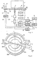
- the apparatus illustrated in Fig. 1 comprises a disc-shaped rotatable member 7, the top view of which taken along the section line A-A of Fig. 1 is shown in Fig. 2.
- the rotatable member 7 is illustrated in a position corresponding to section line B-B of Fig. 2.
- the radiation of the required wavelength is produced by a monochromator 1, the beam of which is emitted through a slit 6.
- the wavelength of the emitted beam depends on the angular position of a control shaft 2 of the monochromator 1.
- the shaft 2 is driven by a motor 3-in this case via a unit 5 changing rotational speed-and the motor 3 is connected to an output of a motor control unit 28.
- the sensor 11 must be selected according to the wavelength of the radiation, it may be for example a photodiode or a photoresistor providing an analog electric signal at its output proportional to the intensity of the beam of radiation applied to its input. This electric signal is applied to the input of a zeroable amplifier 12 providing an amplified analog signal at its output 36.
- the sensor 11 and the amplifier 12 together constitute an intensity measuring unit 34 providing at its output 36 an analog electric signal, i.e. voltage, proportional to the intensity of the beam of radiation applied to its input sensitive to the radiation, and which is zeroed under the effect of a signal applied to its zeroing input 32.
- an analog electric signal i.e. voltage
- the output 36 is connected to the analog input of an analog-to-digital converter 13.
- the analog-to-digital converter 13 converts the analog signal existing at its input into a digital signal at the moment when a signal is applied to its control input 31.
- the digital signal generated by the analog-to-digital converter 13 is transferred via parallel line 30 into a data processing unit 14 strobed by a start signal via control line 24 to read the digital signal.
- a display unit 15 is connected to the data processing unit 14, and the operator can communicate with the data processing unit 14 via an operating console 16.
- the motor control unit 28 is also controlled by the data processing unit 14.
- the apparatus comprises furthermore an auxiliary light source 17 and an auxiliary detector 21 placed oppositely, and the latter is connected to a comparator 19, the output of which is connected to the control input 31 of the analog-to-digital converter 13.
- a further auxialiary light source 18 and a further auxiliary detector 22 are also placed oppositely, and the output of the latter is connected, via a comparator 20, to the zeroing input 32 of the amplifier 12 and to the input 33 initiating a data input operation of the data processing unit 14.
- the apparatus is controlled by means of the openings or slots provided on the disc-shaped rotatable member 7.
- an opening 27, openings 26 and an opening 29 are successively formed in one half of the rotatable member 7 opposite the auxiliary light source 17, and similar openings 27A, 26A and 29A are formed centrally symmetrical with respect to the afore-mentioned openings in the other half of the rotatable member 7, too.
- Openings 23 and 23A are provided opposite the auxiliary light source 18.
- Opposite the exit slit 6 of the monochromator 1 there are sections 25 and 25A transparent to the radiation, sections non-transparent to the radiation being provided between the sections 25 and 25A.
- the apparatus illustrated in Figs. 1 and 2 is applied to perform measurements as described in the following. Having switched on the apparatus and after the insertion of the sample 10, the operator starts the measuring period via the operating console 16 by giving a start signal to the data processing unit 14 e.g. to a microprocessor, thereby the data processing unit 14 powers the motor control unit 28. Thereupon the motor 3 starts to rotate the rotatable member 7.
- the data processing unit 14 e.g. to a microprocessor
- the intensity measuring unit 34 will be set to zero, since the rotatable member 7 prevents the radiation emitted from the monochromator 1 from reaching the sample 10 and so the input of the sensor 11, on the other hand the data processsing unit 14 will be enabled to receive digital output signals of the analog-to-digital converter 13 as a result of the control signal applied to its input 33.
- the comparator 19 provides a signal to the control input 31 of the analog-to-digital converter 13 which measures the zero level signal existing on the output 36 as the radiation is still prevented from reaching the input of the sensor 11 by the rotatable member 7.
- the value of the zero level signal will be stored in the main memory of the data processing unit 14.
- the analog-to-digital converter 13 When the rotatable member 7 is rotated through an angle y, as a result of the light pulse transmitted through the first one of the openings 26 the analog-to-digital converter 13 performs a spectrum signal measurement at a wavelength defined by the angular position of the shaft 2, and the value measured will be stored in the data processing unit 14. While the rotatable member 7 is further rotating, subsequent measurements will be performed corresponding to the openings 26 and the measured values will be stored. Thereafter the path of the beam of radiation emitted from the slit 6 will be cut again by the rotatable member 7 and then a zero level signal measurement and storage of its value will occur again as a result of the light pulse transmitted through the opening 29.
- each of the openings 26 and 26A corresponds to a certain wavelength value, and the total spectrum measurement is performed during a half turn of the rotatable member 7, e.g. in the monochromator 1 the scanning of the wavelength range in the order of increasing wavelength corresponds to the openings 26, while the scanning in the order of decreasing wavelength corresponds to the openings 26A.
- This can be realized e.g. with a monochromator 1 having an oscillating grating.
- the data processing unit 14 controls the number of the rotations of the rotatable member 7 during which the zero level and spectrum data are to be measured and stored. After the required number of measuring periods necessary for the averaging operation to decrease the effect of noise and interferences, the motor 3 is stopped by the data processing unit 14 via the motor control unit 28, and the data containing the stored spectrum and zero level values are processed by the data processing unit 14. In course of this operation the spectrum values are modified by correction values generated by means of the related zero level values, and the spectrum values measured several times at the same wavelength are averaged. The modified spectrum can be graphically displayed by the display unit 15.
- the spectrum values measured and stored are modified on the basis of the zero level values also measured and stored in such a manner that, within the period related to the zero level values corresponding to the openings 27 and 29, the zero level values related to the time values corresponding to the openings 26 are determined by linear interpolation and these latter values are subtracted from the measured spectrum values corresponding to the openings 26.
- the time interval between two subsequent zero level measurements corresponding to opening 27 and 29 be T, then the calculated zero level value at any intermediate time value t is where U o and U T are the measured zero level values corresponding to the openings 27 and 29, and 0Zt%T.
- the modified spectrum value U s ' related to any one of the openings 26 is the following: where t s is the time interval elapsed from the time of the previous zero level measurement corresponding to the opening 27 until the time of the spectrum measurement corresponding to any one of the openings 26, and U s is the stored spectrum value measured at t s .
- the time data are also required.
- these data are also constants defined by the position of the openings provided in the rotatable member 7, so these constants can be taken into consideration when programming the data processing unit 14.
- the value of the time interval T can be e.g. 50 to 400 ms. In a given case, to attain an acceptable accuracy of the spectrum values, it may be sufficient to measure the zero level signal only after the spectrum signal measurement and to suppose a zero level signal equal to zero at the moment of zeroing. For this embodiment only the openings 27 and 27A should be omitted from the rotatable member 7 as illustrated in Fig. 2. If the time interval T is between the zeroing corresponding to the opening 23 and the measurement of the zero level corresponding to the opening 29, the equation (1) can be written as
- FIG. 3 Another possible embodiment of the rotatable member 7 applied in the apparatus given in Fig. 1 is illustrated in Fig. 3.
- This rotatable member 7 consists of four symmetrical quarters. Following the zero setting corresponding to the opening 23 six openings 27 are positioned to initiate zero level measurements between angles a1 and a2. Following this, at an angle ⁇ , the section 25B transparent to the radiation opens the path of the radiation beam emitted from the monochromator 1, and then ten spectrum signal measurements will be performed corresponding to the openings 26 positioned between angles y and 6. It can be seen, that the openings 26 are positioned asymmetrically in the range of the section 25 transparent to the radiation, to provide the necessary time delay for the sensor 11 for the transition from dark into exposed condition.
- the rotatable member 7 cuts off again the path of the radiation beam emitted from the monochromator 1 and, when the dark condition of the sensor 11 is settled again, the sequence of measurements described in the first quarter will be repeated again with new zero level measurements corresponding to the openings 27A.
- one complete turn of the rotatable member 7 will result the measuring of e.g. four different spectrum signals ten times each, and each series consisting of ten spectrum signal measurements is preceded by a zero level signal measurement, too. Following the series consisting of four measurements a zeroing will follow corresponding to the opening 23, followed by the measurement of the next four spectrum values.
- the correction values for the measured and stored spectrum values for each complete turn are determined by an interpolation for the spectrum values corresponding to the openings 26, 26A and 26B based on the four zero level values corresponding to the openings 27, 27A, 27B and 27C, each of them obtained by averaging six measured and stored values, and by an extrapolation for the spectrum values corresponding to the openings 26C, respectively.
- the interpolation is expediently performed by determining a function versus time approximating the zero level values related to each complete turns, and the spectrum values, corresponding to the openings 26, 26A and 26B and obtained by averaging ten values, are to be modified according to this function.
- the value of the funtion is determined e.g. by linear extrapolation, and the spectrum values corresponding to the openings 26C and obtained also by averaging ten values are to be modified according to this extrapolated function.
- FIG. 4 An advantageous embodiment of the zeroable amplifier 12 is illustrated in Fig. 4.
- the input 35 is connected to the non-inverting input of an operational amplifier E1, the output of said amplifier E1 is connected to its inverting input via a feedback resistor R1.
- the output of the amplifier E1 is connected to the inverting input of an operational amplifier E2 through a serial resistor R2, and the output of the amplifier E2 is fed back to the same input via a resistor R3.
- the non-inverting input of the amplifier E2 is connected to the common point of the circuit.
- the output of the amplifier E2 represents the output 36 of the amplifier 12, and at the same time it is connected to the point B of a change-over switch K via a serial resistor R4.
- the change-over switch K is controlled from the input 32 and the point A of it is connected to the common point while the point D is connected to the inverting input of an operational amplifier E3.
- the other input of the amplifier E3 is connected to the common point, and its output is partly fed back to its inverting input via a capacitor C, partly connected to the inverting input of the amplifier E1 via a serial resistor R5.
- the change-over switch K of the amplifier 12 When the change-over switch K of the amplifier 12 is controlled by a zeroing pulse applied to the input 32 to make a galvanic contact between points D and B, the closed control circuit produces zero voltage on the output 36 even if an error voltage differing from zero exists on the input 35.
- the switch K makes a galvanic contact between points D and A thereby setting the amplifier 12 in an amplifying mode and the status of being set to zero is retained until the next zeroing as a consequence of the charge stored in the capacitor C.
- the frequency of the zeroing operation should be suitably selected according to the time constants of the circuit.
- FIG. 5 A further embodiment of the apparatus according to the invention is illustrated in Figs. 5 and 6, where the elements corresponding to the embodiment illustrated in Fig. 1 are provided with the same reference numbers.
- the top view of the rotatable member 7 taken along the section line C-C of Fig. 5 is shown in Fig. 6.
- Fig. 5 a sectional view of the rotatable member 7 can be seen taken along the section line D-D of Fig. 6.
- a zeroing pulse will be transmitted from one output of the timing circuit 40 to the zeroing input 32 of the intensity measuring unit 34 and then, after a certain time delay but before the rotatable member 7 is rotated through the angle ⁇ , a pulse will be transmitted from the other output of the timing circuit 40 to the control input 31 of the analog-to-digital converter 13.
- the zero level signal of the intensity measuring unit 34 is measured by the analog-to-digital converter 13.
- the timing circuit 40 starts to transmit a series of pulses to the input 31 of the analog-to-digital converter 13.
- Timing circuit 40 can be constructed from common digital circuits and delay elements, but it can be realized by a microprocessor, too.
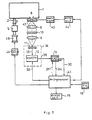
- FIG. 7 A further embodiment of the apparatus according to the invention is illustrated in Fig. 7, where the elements corresponding to the embodiment illustrated in Fig. 1 are provided with the same reference numbers.
- the complete apparatus is controlled by a microprocessor 41 with an operating console 16 and a display unit 15 connected to it.
- the microprocessor 41 controls a stepping motor 45 via a motor control unit 46, which stepping motor 45 drives the shaft 2 controlling the wavelength of the monochromator 1 via the unit 5 changing the speed of rotation.
- the microprocessor 41 controls an electromagnet 43 via a driver unit 44, which electromagnet 43 operates a diaphragm 42 cutting off and transmitting, respectively, the radiation beam emitted form the exit slit 6 of the monochromator 1.
- the microprocessor 41 further controls the zeroing of the intensity measuring unit 34 by a signal applied to the input 32, and the operation of the analog-to-digital converter 13 by a signal applied to the input 31.
- the output digital signals form the digital-to- analog converter 13 will also be transmitted to the microprocessor41 via the line 30, and these digital signals will be stored in the memory of the microprocessor 41.
- the measuring process is started by a start signal received from the operating console 16 and is completely controlled by the microprocessor 41.
- the microprocessor 41 After storing the required zero level signal and spectrum values, the microprocessor 41 generates the function approximating the variations of the zero level signal by means of interpolation or interpolation and extrapolation based on the stored zero level values, calculates the correction values given by this function, and subtracts the correction values from the stored spectrum values. If necessary, the microprocessor 41 performs the averaging of the stored spectrum values and zero level values, respectively, before performing the arithmetic operations described above, in order to decrease the effect of noise and interferences always existing in measurements.
- the microprocessor 41 itself can be realized from widely known commercial circuit elements.
- Switching on and off the radiation beam may also be effected under purely electronic control, e.g. when the monochromator is a tunable laser light source.
- the apparatus according to the invention it may be advantageous to utilize an integrating type analog-to-digital converter 13.
- both the six measurements corresponding to the openings 27 and the ten measurements corresponding to the openings 26 may be replaced by one measurement each, and at the same time the proper rejection of the noise and interferences is also effected.
- the averaging operation to be performed in the course of the data processing may be replaced by an analog integration resulting in a significant reduction of the memory requirement of the data processing unit and in the reduction of the time necessary for the data processing.
Landscapes
- Physics & Mathematics (AREA)
- Spectroscopy & Molecular Physics (AREA)
- General Physics & Mathematics (AREA)
- Analytical Chemistry (AREA)
- General Health & Medical Sciences (AREA)
- Health & Medical Sciences (AREA)
- Life Sciences & Earth Sciences (AREA)
- Chemical & Material Sciences (AREA)
- Mathematical Physics (AREA)
- Biochemistry (AREA)
- Theoretical Computer Science (AREA)
- Engineering & Computer Science (AREA)
- Immunology (AREA)
- Pathology (AREA)
- Spectrometry And Color Measurement (AREA)
- Analysing Materials By The Use Of Radiation (AREA)
- Investigating Or Analysing Materials By Optical Means (AREA)
Claims (23)
Priority Applications (1)
| Application Number | Priority Date | Filing Date | Title |
|---|---|---|---|
| AT83103538T ATE32785T1 (de) | 1982-04-14 | 1983-04-12 | Verfahren und einrichtung zur messung des spektrums von materialien. |
Applications Claiming Priority (2)
| Application Number | Priority Date | Filing Date | Title |
|---|---|---|---|
| HU821139A HU183889B (en) | 1982-04-14 | 1982-04-14 | Method and apparatus for measuring the spectrum of materials |
| HU113982 | 1982-04-14 |
Publications (3)
| Publication Number | Publication Date |
|---|---|
| EP0091692A2 EP0091692A2 (de) | 1983-10-19 |
| EP0091692A3 EP0091692A3 (en) | 1984-09-05 |
| EP0091692B1 true EP0091692B1 (de) | 1988-03-02 |
Family
ID=10953004
Family Applications (1)
| Application Number | Title | Priority Date | Filing Date |
|---|---|---|---|
| EP83103538A Expired EP0091692B1 (de) | 1982-04-14 | 1983-04-12 | Verfahren und Einrichtung zur Messung des Spektrums von Materialien |
Country Status (5)
| Country | Link |
|---|---|
| US (1) | US4632549A (de) |
| EP (1) | EP0091692B1 (de) |
| AT (1) | ATE32785T1 (de) |
| DE (1) | DE3375824D1 (de) |
| HU (1) | HU183889B (de) |
Cited By (2)
| Publication number | Priority date | Publication date | Assignee | Title |
|---|---|---|---|---|
| WO1989010025A1 (en) * | 1988-04-06 | 1989-10-19 | Bodenseewerk Perkin-Elmer & Co. Gmbh | Device for producing a magnetic field in an atomic absorption spectrometer |
| WO1991009298A1 (en) * | 1989-12-19 | 1991-06-27 | Komi Nauchny Tsentr Uralskogo Otdelenia Akademii Nauk Sssr | Method and device for obtaining metric characteristics of spectrochemical parameters of analysed materials |
Families Citing this family (11)
| Publication number | Priority date | Publication date | Assignee | Title |
|---|---|---|---|---|
| US4893259A (en) * | 1988-06-02 | 1990-01-09 | The Perkin-Elmer Corporation | Standardization of spectral lines |
| US5270797A (en) * | 1989-07-20 | 1993-12-14 | Brooklyn College Foundation | Method and apparatus for determining a material's characteristics by photoreflectance using improved computer control |
| US5260772A (en) * | 1989-07-20 | 1993-11-09 | Pollak Fred H | Method and apparatus for determining a material's characteristics by photoreflectance |
| US5255071A (en) * | 1989-09-13 | 1993-10-19 | Pollak Fred H | Photoreflectance method and apparatus utilizing acousto-optic modulation |
| US5643796A (en) * | 1994-10-14 | 1997-07-01 | University Of Washington | System for sensing droplet formation time delay in a flow cytometer |
| KR100354852B1 (ko) * | 1994-12-09 | 2003-04-21 | 포스 일렉트릭 에이/에스 | 정보획득방법 |
| JP3250426B2 (ja) * | 1995-09-27 | 2002-01-28 | 安藤電気株式会社 | 光スペクトラム測定装置 |
| US6927859B2 (en) | 2001-03-08 | 2005-08-09 | The Hong Kong Polytechnic University | Microdensitometer system with micrometer resolution for reading radiochromic films |
| JP2004247380A (ja) * | 2003-02-12 | 2004-09-02 | Mitsubishi Electric Corp | ピエゾ電場の評価方法 |
| CN101169340B (zh) * | 2006-10-27 | 2010-12-08 | 鸿富锦精密工业(深圳)有限公司 | 主板发光二极管检测装置及方法 |
| US7835004B2 (en) * | 2007-07-03 | 2010-11-16 | Mine Safety Appliances Company | Gas sensors and methods of controlling light sources therefor |
Family Cites Families (9)
| Publication number | Priority date | Publication date | Assignee | Title |
|---|---|---|---|---|
| US3131349A (en) * | 1954-02-23 | 1964-04-28 | Applied Physics Corp | Spectrophotometer pulse amplitude ratio measuring means with feedback amplifier for noise and drift compensation |
| US3207996A (en) * | 1961-11-17 | 1965-09-21 | Beckman Instruments Inc | Signal comparison circuit |
| US4035083A (en) * | 1972-05-30 | 1977-07-12 | Woodriff Ray A | Background correction in spectro-chemical analysis |
| GB1401942A (en) * | 1973-03-16 | 1975-08-06 | Chrysler Corp | Method and system for the infrared analysis of gases |
| US3935463A (en) * | 1974-12-05 | 1976-01-27 | Milton Roy Company | Spectrophotometer |
| AT349791B (de) * | 1975-10-17 | 1979-04-25 | Gao Ges Automation Org | Verfahren zur identifizierung von fluor- eszenzstoffen und spektral absorbierendes filter zur durchfuehrung des verfahrens |
| US4299485A (en) * | 1979-03-05 | 1981-11-10 | Pye Electronic Products Limited | Spectrophotometer |
| US4357673A (en) * | 1980-04-18 | 1982-11-02 | Hewlett-Packard Company | Apparatus for performing measurements and error analysis of the measurements |
| JPS585669A (ja) * | 1981-06-30 | 1983-01-13 | Shimadzu Corp | ベ−スライン補正方法 |
-
1982
- 1982-04-14 HU HU821139A patent/HU183889B/hu not_active IP Right Cessation
-
1983
- 1983-04-12 AT AT83103538T patent/ATE32785T1/de not_active IP Right Cessation
- 1983-04-12 DE DE8383103538T patent/DE3375824D1/de not_active Expired
- 1983-04-12 EP EP83103538A patent/EP0091692B1/de not_active Expired
- 1983-04-14 US US06/485,049 patent/US4632549A/en not_active Expired - Fee Related
Cited By (2)
| Publication number | Priority date | Publication date | Assignee | Title |
|---|---|---|---|---|
| WO1989010025A1 (en) * | 1988-04-06 | 1989-10-19 | Bodenseewerk Perkin-Elmer & Co. Gmbh | Device for producing a magnetic field in an atomic absorption spectrometer |
| WO1991009298A1 (en) * | 1989-12-19 | 1991-06-27 | Komi Nauchny Tsentr Uralskogo Otdelenia Akademii Nauk Sssr | Method and device for obtaining metric characteristics of spectrochemical parameters of analysed materials |
Also Published As
| Publication number | Publication date |
|---|---|
| DE3375824D1 (en) | 1988-04-07 |
| US4632549A (en) | 1986-12-30 |
| ATE32785T1 (de) | 1988-03-15 |
| EP0091692A3 (en) | 1984-09-05 |
| HU183889B (en) | 1984-06-28 |
| EP0091692A2 (de) | 1983-10-19 |
Similar Documents
| Publication | Publication Date | Title |
|---|---|---|
| EP0091692B1 (de) | Verfahren und Einrichtung zur Messung des Spektrums von Materialien | |
| US4412744A (en) | Absolute spectrophotometer | |
| CA1084148A (en) | Electro-optical ranging system for distance measurements to moving targets | |
| US3428401A (en) | Flame photometer | |
| US3661462A (en) | Spectrophotometer for measuring thickness or weight of water-containing coatings | |
| US4225233A (en) | Rapid scan spectrophotometer | |
| US4236826A (en) | Apparatus for optically measuring a property of an object | |
| US3531202A (en) | Spectrometer readout system | |
| EP0306337B1 (de) | Spektralphotometer | |
| US6462819B1 (en) | Light measuring apparatus and colorimeter | |
| US5825484A (en) | Optical spectrum measuring device | |
| US3588252A (en) | Background suppression system for optical spectrometer | |
| US3981586A (en) | Continuously monitoring ratiometer | |
| US4577105A (en) | Method of determining masses of absorbing components of a sample in a test volume and a device for implementation of this method | |
| KR100247171B1 (ko) | 광검출기의 진폭선형성 | |
| US4043676A (en) | Photometer | |
| JP3005364B2 (ja) | 光学的試料測定装置 | |
| JPS6212847B2 (de) | ||
| US3845400A (en) | Signal analyzing apparatus | |
| US6414310B1 (en) | Automatic control circuit for infrared detectors | |
| JPH05264352A (ja) | 分光光度計 | |
| US4176958A (en) | Automatic loop gain adjustment for optical null spectrophotometers | |
| US3790283A (en) | Total loop gain indicator for optical null spectrophotometer | |
| US4657384A (en) | Photoelectric device | |
| EP0096316A1 (de) | Methode und Vorrichtung zur Messung von Spektren |
Legal Events
| Date | Code | Title | Description |
|---|---|---|---|
| PUAI | Public reference made under article 153(3) epc to a published international application that has entered the european phase |
Free format text: ORIGINAL CODE: 0009012 |
|
| AK | Designated contracting states |
Designated state(s): AT DE FR GB IT SE |
|
| PUAL | Search report despatched |
Free format text: ORIGINAL CODE: 0009013 |
|
| AK | Designated contracting states |
Designated state(s): AT DE FR GB IT SE |
|
| 17P | Request for examination filed |
Effective date: 19841016 |
|
| GRAA | (expected) grant |
Free format text: ORIGINAL CODE: 0009210 |
|
| AK | Designated contracting states |
Kind code of ref document: B1 Designated state(s): AT DE FR GB IT SE |
|
| REF | Corresponds to: |
Ref document number: 32785 Country of ref document: AT Date of ref document: 19880315 Kind code of ref document: T |
|
| REF | Corresponds to: |
Ref document number: 3375824 Country of ref document: DE Date of ref document: 19880407 |
|
| ET | Fr: translation filed | ||
| ITF | It: translation for a ep patent filed |
Owner name: MODIANO & ASSOCIATI S.R.L. |
|
| PLBE | No opposition filed within time limit |
Free format text: ORIGINAL CODE: 0009261 |
|
| STAA | Information on the status of an ep patent application or granted ep patent |
Free format text: STATUS: NO OPPOSITION FILED WITHIN TIME LIMIT |
|
| 26N | No opposition filed | ||
| PGFP | Annual fee paid to national office [announced via postgrant information from national office to epo] |
Ref country code: GB Payment date: 19900409 Year of fee payment: 8 |
|
| PGFP | Annual fee paid to national office [announced via postgrant information from national office to epo] |
Ref country code: SE Payment date: 19900412 Year of fee payment: 8 |
|
| PGFP | Annual fee paid to national office [announced via postgrant information from national office to epo] |
Ref country code: AT Payment date: 19900417 Year of fee payment: 8 |
|
| PGFP | Annual fee paid to national office [announced via postgrant information from national office to epo] |
Ref country code: FR Payment date: 19900426 Year of fee payment: 8 |
|
| ITTA | It: last paid annual fee | ||
| PGFP | Annual fee paid to national office [announced via postgrant information from national office to epo] |
Ref country code: DE Payment date: 19900629 Year of fee payment: 8 |
|
| PG25 | Lapsed in a contracting state [announced via postgrant information from national office to epo] |
Ref country code: GB Effective date: 19910412 Ref country code: AT Effective date: 19910412 |
|
| PG25 | Lapsed in a contracting state [announced via postgrant information from national office to epo] |
Ref country code: SE Effective date: 19910413 |
|
| GBPC | Gb: european patent ceased through non-payment of renewal fee | ||
| PG25 | Lapsed in a contracting state [announced via postgrant information from national office to epo] |
Ref country code: FR Effective date: 19911230 |
|
| PG25 | Lapsed in a contracting state [announced via postgrant information from national office to epo] |
Ref country code: DE Effective date: 19920201 |
|
| REG | Reference to a national code |
Ref country code: FR Ref legal event code: ST |
|
| EUG | Se: european patent has lapsed |
Ref document number: 83103538.1 Effective date: 19911108 |