EP0091673A2 - Appareil avec filtres tubulaires - Google Patents
Appareil avec filtres tubulaires Download PDFInfo
- Publication number
- EP0091673A2 EP0091673A2 EP83103441A EP83103441A EP0091673A2 EP 0091673 A2 EP0091673 A2 EP 0091673A2 EP 83103441 A EP83103441 A EP 83103441A EP 83103441 A EP83103441 A EP 83103441A EP 0091673 A2 EP0091673 A2 EP 0091673A2
- Authority
- EP
- European Patent Office
- Prior art keywords
- filter
- partition
- housing
- assembly
- opening
- Prior art date
- Legal status (The legal status is an assumption and is not a legal conclusion. Google has not performed a legal analysis and makes no representation as to the accuracy of the status listed.)
- Granted
Links
Images


Classifications
-
- B—PERFORMING OPERATIONS; TRANSPORTING
- B01—PHYSICAL OR CHEMICAL PROCESSES OR APPARATUS IN GENERAL
- B01D—SEPARATION
- B01D46/00—Filters or filtering processes specially modified for separating dispersed particles from gases or vapours
- B01D46/88—Replacing filter elements
-
- B—PERFORMING OPERATIONS; TRANSPORTING
- B01—PHYSICAL OR CHEMICAL PROCESSES OR APPARATUS IN GENERAL
- B01D—SEPARATION
- B01D46/00—Filters or filtering processes specially modified for separating dispersed particles from gases or vapours
- B01D46/0002—Casings; Housings; Frame constructions
- B01D46/0005—Mounting of filtering elements within casings, housings or frames
- B01D46/0006—Filter elements or cartridges installed in a drawer-like manner
-
- B—PERFORMING OPERATIONS; TRANSPORTING
- B01—PHYSICAL OR CHEMICAL PROCESSES OR APPARATUS IN GENERAL
- B01D—SEPARATION
- B01D46/00—Filters or filtering processes specially modified for separating dispersed particles from gases or vapours
- B01D46/02—Particle separators, e.g. dust precipitators, having hollow filters made of flexible material
Definitions
- the present invention relates to bag filter assemblies for separating particulate matter from a flow of gaseous medium and is applicable to a baghouse in which the particulate matter is deposited on the outside of filter bags suspended in the baghouse.
- the filter bags are suspended in a transverse partition within the filter housing and the gaseous medium is caused to flow through the housing in a direction such that the medium flows from the outside toward the inside of the filter bags and deposits the particulate matter on the exterior surface of the filter bags.
- Means is provided to periodically dislodge the particulate matter which has built up upon the exterior surfaces of the filter bags and the dislodged particulate matter is discharged from the bottom of the filter housing.
- a conventional apparatus for effecting such dislodgement is a bank of nozzles which are periodically activated to direct jets of air into the interiors of the filter bags.
- the filter bags may be cleaned sequentially or in unison by suitable programming of the activation of the jets.
- cages or frames are inserted into the bags to maintain the bags open and prevent them from collapsing which would impede the flow of medium therethrough.
- An alternate method of replacing the filter bags is provided by an access door in the baghouse at the dirty side of the partition.
- a worker may enter the baghouse and remove the filter bags from the underside of the partition and this operation requires the installation of special supports to enable the workers to perform their necessary operations within the baghouse chamber. Such supports may impair the discharge of particulate matter dislodged from the filter bags.
- a cassette-type filter has been illustrated and described in U.S. Patent No. 4,141,704 of AB Svenska Flaktfabriken.
- the filter bags are embodied in a cassette which includes an internal support for the internal frame or cage for supporting the filter bags and a supPOrt structure which is fitted into the baghouse and latched into position for air-tight engagement of the cassette within the baghouse.
- a supPOrt structure which is fitted into the baghouse and latched into position for air-tight engagement of the cassette within the baghouse.
- the present invention provides an improved baghouse in which the filter bags may be displaced from the filter chamber for servicing, such as replacement and repair in a simple and efficient manner.
- the present invention provides a baghouse in which the transverse partition which mounts the bags is formed integrally with an access door of the housing so that upon displacement of the access door, the supporting partition is similarly displaced to a position which exposes the filter bags mounted in the partition for servicing.
- the present invention provides an improved sealing arrangement between the partition and the housing and also between the individual filter bags and the partition so that flow of gaseous medium through the housing must pass through the filter bags so as to deposit the particulate matter carried by the flow on the exterior surface of the filter bags.
- the sealing arrangement also protects the operating mechanism for displacing the partition against accumulation of particulate matter.
- the invention also provides an improved mounting arrangement for the filter bags in the partition which facilitates removal of the dirty filter bags and replacement.
- the present invention provides a filter unit for mounting in the partition having a collar at the top for releasable engagement with the partition and simple but effective means to anchor the open end of the filter bag on the collar so that it is suspended within the housing.
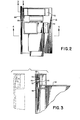
- the baghouse filter 21 shown in Figures 1 to 9 includes a filter housing 22 having an open side enclosed by a frame 23 which cooperates with a closure door 24 carrying a transverse partition (or tube sheet) 25 mounting 'a plurality of individual filter units 26 in a bank.
- the bank of filter units may be removed from the housing 22 through the access opening 27 provided by the open side, the opening being at least coextensive with the outline of the bank of filter units.
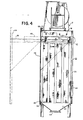
- the housing 22 has a dirty air or other gaseous medium inlet 32 adjacent its lower end in the wall 33 opposite the open side frame 23.
- an outlet hood 35 is provided to withdraw clean or gaseous medium from above the partition 25.
- the gaseous medium is drawn through the outlet connection 35 by a blower 36 which exhausts the cleaned gaseous medium to the atmosphere or through duct work to other treatment facilities.
- filter-cleaning means is provided to dislodge particulate matter which accumulates on the individual filter units.
- the baghouse filter incorporates means to project jets of compressed air into the centers of the individual filter units.
- the jet means comprises a series of supply pipes 38 overlying the open ends of the filter units and having downwardly directed nozzles 39 operable to project jets of compressed air into the centers of the filter units to dislodge particulate matter which might otherwise accumulate on the exterior surface of the filter units by causing a reverse flow through the filter material.
- the supply pipes 38 are fed with compressed air from a main supply line 40 through valves 41 which are controlled for either operation in unison at specified intervals or operation in sequence by a control unit 42 which may be responsive to the back pressure in the inlet side of the filter housing.
- the particulate matter dislodged from the outside of the individual filter units is collected in the bottom of the housing as indicated at 43, from which it may be discharged through a dust outlet 44.
- the dust outlet may be a simple valve which is periodically opened or may lead into a sluice-type arrangement for continuous discharge of particulate material without permitting escape of dirty gaseous medium with the material.
- the partition 25 is mounted for unidirectional displacement with the door 24 as it is moved between its opened and closed positions.
- the door 24 is carried by the partition which, in turn, is supported on roller-guides 45 slidably mounted on horizontal trackways 46 secured to the side walls of the housing.
- the partition 25 has a channel member 47 cooperating with the roller-guides 45 to provide support for the partition as it is displaced in the trackways 46.
- the mounting of the partition in the housing is similar to the mounting of a file drawer in a file cabinet. In this way, when the door 24 is opened by sliding it out on the tracks 46, the entire side of the housing within the frame 23 is open to provide an access opening 27 into the filter chamber above and below the partition 25. As shown, the size of the access opening is sufficiently great to permit the partition 25 with the multiple filter units 26 depending therefrom, to pass out of. the filter chamber where they are readily accessible.
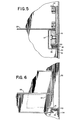
- sealing means is provided to seal between the partition 25 and the side walls of the housing which mount the tracks 46.
- the sealing means is fixed to the underside of the track 46 and consists of an elastomeric sealing element 48 having a free sealing lip 49 at its outer end which rides against the channel member 47 to provide a seal between the side wall of the housing and the partition 25.
- the elastomeric member has a generally flat body portion 50 which is retained between angle members 51 and 52 which serve as a holder for the sealing element.
- the flexible lip portion 49 of the sealing element extends beyond the angle members 51 and 52 and is formed with an angular orientation relative to the body portion 50.
- the lip 49 bears against the upper surface of the lower flange of the channel member 47 which projects toward the wall mounting the angle members 51 and 52 and overlaps the outwardly projecting legs of the angle members to provide a labyrinth passage between the angle member 52 and the channel member 47, the sealing lip 49 being mounted to interrupt this passage.
- a similar sealing arrangement is provided between the rear edge of the partition 25 and the wall 33 of the housing 22.
- the inner or rear edge of the partition 25 is provided with a reinforcing channel member 57 extending across the entire width of the partition member, the channel member having an upstanding web and rearwardly directed flanges in a manner similar to the channel member 47.
- a sealing assembly is mounted on the wall 33 to cooperate with the lower flange of the channel member 57.
- the sealing assembly 58 is similar to the sealing assembly 48, consisting of an elastomeric sealing element having a sealing lip 59 and a body portion 60 retained between angle members 61 and 62.
- the sealing assembly 58 extends across the full width of the chamber between the opposite tracks 46 and meets the sealing assemblies 48 to provide a continuous air-tight seal around three sides of the partition 25 when it is in its operative position within the housing.
- the fourth side of the partition 25 is mounted directly on the door 24.
- the door 24 is effectively sealed against the housing 22 to prevent leakage through the access opening 27 when the door is in its operative position closing the access opening.
- a peripheral seal is provided about the entire periphery of the door 24 to cooperate with the frame 23.
- An angle-iron reinforcing component 65 is spaced inwardly from the outer periphery of the door so that the projecting flange fits within the access opening within the frame 23.
- the angle member 65 is spaced inwardly from the outer edge of the door 24 and cooperates with a sealing assembly 68 to straddle the frame 23.
- the sealing assembly 68 is similar to the sealing assemblies 48 and 58 described above including an elastomeric sealing element having a lip 69 and a body part 70.
- an abutment strip 73 is mounted on the sealing assembly 68 to provide an abutment on the door to serve as a stop against the frame 23 of the housing 22.
- the sealing lip 69 is deflected into sealing engagement with the frame 23, but is prevented from being pinched. Since the sealing unit 68 is disposed about the entire periphery of the door 24, an effective seal is provided for the access opening when the door is closed and the partition 25 is in the operative position.
- the filtering assembly consisting of the partition 25 and filter units 26 moves unidirectionally in a continuous path defined by the trackways 46 between said open and closed positions, the final.increment of movement into the closed position being effective to position the sealing assemblies 58 and 68 in their respective sealing positions, so that there is no need for transverse displacement of the assembly to effect a proper seal.
- Suitable sealing arrangements are provided between the partition sealing assembly 48 and the door seal 68 to prevent leakage around the partition when the door is closed.
- each filter opening 71 is generally circular in outline and has a plurality of recesses 72, in the present instance two, spaced about its periphery. With two recesses 72, they are spaced diametrically opposite.
- Each opening is designed to accommodate a filter unit consisting of a filter bag closed at one end and open at the other end, the open end having mounting means for releasably engaging the filter unit in the filter opening 71.
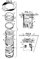
- Each filter unit 26, as shown in Figures 7 through 9, includes a filter bag 75 of suitable filter material which may be designed for one-time usage or repeated usage, according to the character of the gaseous flow being filtered in the baghouse.
- the filter bag. 75 is generally cylindrical in form and is closed at the bottom end and open at the top.
- a cage 76 is fitted in the interior of the bag.
- the filter cage 76 comprises a ring 77 adapted to fit within the open end of the filter bag 75.
- a plurality of finger rods forming the cage extending the free length of the filter bag 75 so as to maintain it in its generally cylindrical configuration.
- the ring 77 is adapted to telescopically engage over a mounting collar 81 having a diameter corresponding to the diameter of the filter opening 71 in the partition 25 and being of generally cylindrical form so as to engage within the ring 77.
- the ring 77 is split as indicated at 79 to permit limited expansion and contraction of the ring to fit snugly over the bottom portion of the collar.
- the collar 81 has a medial flange 82 projecting outwardly at a level below the upper extremity of the collar and above the lower extremity. The distance between the flange 82 and the bottom of the collar is less than the clear space within the ring 77 above the upper extremities of the fingers 78, so that the flange assures that the upper ends of the fingers 78 are positioned below the lower edge of the collar 81.
- the lower portion of the collar 81 below the flange 82 has a circumferential groove 84 and the ring 77 has a corresponding circumferential groove 85 which is adapted to seat within the groove 84 when the ring 77 is telescopically engaged with the collar 81 (see Figure 7).
- the filter unit is retained in assembled condition by an anchor strap 86 which circumscribes the mounting collar 81, the ring 77, and the upper open end of the filter bag 75 to clamp these parts together into a unitary filter assembly.
- the clamping device 86 is shown as a conventional strap which is adapted to be screwed into tight engagement, but other clamping devices may be used With good effect where it is desired to facilitate the disassembly and reassembly of the filter unit.
- the cage of filter assembly may be fabricated as an integral structure so that the clamping device need only function to anchor the filter bag on the integral cage. In such case an elastic band may be a sufficient clamping device.
- the collar is provided with a pair of locking tabs 87 projecting outwardly from the upper edge.
- the width and length of the locking tabs 87 corresponds to the width and length of the recesses 72 so that the locking tabs 87 may pass through the recesses 72 when the collar is displaced axially through the opening 71.
- the assembled filter unit 76 is adapted to be sealingly engaged in the filter opening 71 in a simple and effective manner.
- the filter unit has a sealing ring 88 mounted between the flange 82 and the locking tabs 87.
- the sealing ring 88 is an elastomeric annulus of generally U-shaped cross section having a base portion 89 adapted to fit within the angle provided between the flange 82 and the cylindrical upper portion of the collar 81.
- the collar 81 is made in two telescopically-engaged cylindrical parts, and the sealing ring 88 is assembled between the flange 82 and the tabs 87 before the parts are interlocked by the formation of the groove 84.
- the resilient flexible nature of the annulus 88 enables it to seat snugly against the upper portion of the collar 81 so that the base portion 89 seals against the cylindrical portion of the collar.
- the lower flange of the annulus bears against the flange 82 to provide a seal and the upper flange 91 is flared radially and axially (see Figure 7) to engage the undersurface of the partition 25 in the marginal area surrounding the aperture 71.
- the projection of the free flange 91 is sufficiently great to cover the recesses 72 of the opening 71 and prevent the escape of air or dirty gaseous medium through the recesses, thereby avoiding bypassing of the filter bag 75 by the medium flowing through the filter chamber.
- each tab is inclined relative to the plane of the partition 25 so that when the collar is twisted counterclockwise in the opening 71 the leading edge of each tab is higher than the trailing edge.
- engagement of the tab through the recesses 72 and twisting of the collar a partial turn causes the sloping body of the tab to act as camming surfaces against the edges of the recesses 72, displacing the collar upwardly as shown in Figure 7 and compressing the sealing element 88 between the flange 82 and the undersurface of the partition 25.
- the inclination of the tabs 87 is best illustrated in Figure 8.
- the filter unit 26 is sealingly and securely engaged in the opening 71 by simple axial displacement followed by a fractional twist about its axis.
- a simplified embodiment of a filter unit is shown at 93 in Figures 10-12 inclusive.
- Such filter unit is adapted to be mounted in the partition 25 which has openings 71 With recesses 72 as described above in connection with the filter unit of Figures 7-9.
- the simplified filter unit 93 includes a filter bag 95 which is similar to the bag 75, being generally cylindrical in form having a closed bottom and an open top.
- a cage 96 is fitted into the interior of the bag, and in the present instance the cage 96 has an upper ring portion 97 which is continuous and uninterrupted about its periphery and has an outwardly projecting rib 98 approximately midway of its height.
- the rib 98 serves not only to reinforce the cylindrical ring portion 97 but also provides a sealing portion to cooperate with a sealing annulus 108 which circumscribes the ring 97.
- the ring 97 constitutes a mounting collar for the filter unit 93 which cooperates with any opening 71.
- the upper edge of the ring 97 is notched at diametrically opposite positions as indicated at 99, the spacing of the notches 99 corresponding to the spacing of the recesses 72 in the opening 71 of the partition 25.
- Locking tabs 102 project outwardly through the notches 99 and as shown in Figures 11 and 12 the tabs 102 register with the recesses 72 so as to pass through the recesses 72 when the filter unit 93 is displaced axially upward from the space below the partition 25 through the aperture 71.
- the tabs 102 comprise projecting leg portions of angle members 103 secured to the interior wall of the ring 97 and having body portions extending axially downward from the recesses 99 to overlie the inwardly- directed side of the reinforcing rib 98.
- the angle members 103 may be tack welded or otherwise securely mounted to the ring 97 to provide a unitary assembly of the filter unit 93.
- the sealing member 108 is designed not only to seal the filter unit within the opening and prevent escape of gas around the periphery of the filter unit, but also serves to bias the filter unit in place and cause the tabs 102 to seat firmly against the upper surface of the partition 25 in the marginal area surrounding the opening 71.
- the sealing member 108 is compressed against the undersurface of the partition 25 and provides frictional resistance against displacement of the filter unit 93 from the opening 71.
- the sealing element is in the form of a hollow cylinder surrounding the ring 97.
- the lower edge of the sealing member 108 has a bead 111 disposed beyond a generally flat cylindrical portion 109 which fits between the ring 97 and the upper end of the filter bag 95.
- the bead serves to anchor the sealing element in place on the ring 97 when the unit is assembled by the attachment of a clamping strap 106 about the open end of the filter bag 95.
- the clamp 106 unites the filter bag 95, the sealing element 108 and the cage ring 97 into a unitary assembly 93.
- the sealing member 108 has a groove adapted to engage over the rib 98 so as to provide an effective seal between the sealing element 108 and the ring 97. If the sealing element is securely mounted on the cage without the need for the clamp 106, it.may terminate above the clamp, so that the clamp or other suitable retainer simply serves to anchor the bag on the cage.
- the sealing element is provided with a flared lip 114 which is self-biased into engagement with the undersurface of the partition 25.
- the radial extension of the flaired lip 114 is greater than the width of the recesses 72 in the periphery of the opening 71 so that the lip 114 circumscribes the entire opening on the underside of the partition.
- the character of the elastomeric material forming the sealing element 108 is sufficiently stiff so that the stiffness in the elastomeric material provides a bias which reacts against the undersurface of the partition 25 and presses the filter assembly downwardly so as to seat the lugs 102 firmly against the upwardly directed marginal portion of the opening 71.
Priority Applications (1)
| Application Number | Priority Date | Filing Date | Title |
|---|---|---|---|
| AT83103441T ATE35914T1 (de) | 1982-04-09 | 1983-04-08 | Schlauchfiltergeraet. |
Applications Claiming Priority (2)
| Application Number | Priority Date | Filing Date | Title |
|---|---|---|---|
| US367046 | 1982-04-09 | ||
| US06/367,046 US4435197A (en) | 1982-04-09 | 1982-04-09 | Baghouse filter |
Publications (3)
| Publication Number | Publication Date |
|---|---|
| EP0091673A2 true EP0091673A2 (fr) | 1983-10-19 |
| EP0091673A3 EP0091673A3 (en) | 1984-08-22 |
| EP0091673B1 EP0091673B1 (fr) | 1988-07-27 |
Family
ID=23445719
Family Applications (1)
| Application Number | Title | Priority Date | Filing Date |
|---|---|---|---|
| EP83103441A Expired EP0091673B1 (fr) | 1982-04-09 | 1983-04-08 | Appareil avec filtres tubulaires |
Country Status (4)
| Country | Link |
|---|---|
| US (1) | US4435197A (fr) |
| EP (1) | EP0091673B1 (fr) |
| AT (1) | ATE35914T1 (fr) |
| DE (1) | DE3377468D1 (fr) |
Cited By (4)
| Publication number | Priority date | Publication date | Assignee | Title |
|---|---|---|---|---|
| EP0321895A1 (fr) * | 1987-12-23 | 1989-06-28 | Bühler GmbH | Couvercle de fermeture pour des filtres à air et à gaz |
| CH701263A1 (de) * | 2009-06-15 | 2010-12-15 | Edwin Eisenegger | Schlauchfiltervorrichtung. |
| WO2013023828A1 (fr) * | 2011-08-16 | 2013-02-21 | Mann+Hummel Gmbh | Tubulure de raccordement pour tuyaux de filtre |
| EP2841180A1 (fr) * | 2012-04-27 | 2015-03-04 | Total Raffinage Chimie | Dispositif de filtre a gaz muni de moyen de fixation et retrait des elements filtrants pour la maintenance. |
Families Citing this family (39)
| Publication number | Priority date | Publication date | Assignee | Title |
|---|---|---|---|---|
| US5053063A (en) * | 1988-08-18 | 1991-10-01 | Sisk David E | Dust filtering and collection system |
| US5277704A (en) * | 1992-08-21 | 1994-01-11 | Airecon Manufacturing Corp. | Mist collector |
| US5223008A (en) * | 1992-08-24 | 1993-06-29 | Flex-Kleen Corp. | Horizontally mounted filter cartridge dust collector |
| GB2279268B (en) * | 1993-05-04 | 1997-07-23 | Technical Fabricators | Fluid conduits with filters and filters therefor |
| US5636422A (en) * | 1993-05-27 | 1997-06-10 | Pyron; Donald | Baghouse filter installation manifold |
| US5398386A (en) * | 1993-05-27 | 1995-03-21 | Pyron; Donald | Process for rejuvenating baghouse filter cartridges |
| USRE37163E1 (en) | 1994-05-06 | 2001-05-08 | Bha Group Holdings, Inc. | Unitary filter cartridge |
| US6726735B1 (en) | 1994-05-06 | 2004-04-27 | Bha Group Holdings, Inc. | Unitary filter cartridge |
| US5632791A (en) * | 1994-12-06 | 1997-05-27 | Bha Group, Inc. | Unitary filter cartridge |
| US5637124A (en) * | 1995-03-23 | 1997-06-10 | Helical Dynamics, Inc. | Modular air cleaning system |
| US5660608A (en) * | 1995-10-12 | 1997-08-26 | Eco Corporation | Filter cartridge boot |
| US5803939A (en) * | 1997-04-24 | 1998-09-08 | Alanco Environmental Resources Corp. | Industrial dust collector and method for its use |
| US6294002B1 (en) | 1999-10-26 | 2001-09-25 | W. Mcgee And Associates, Llc | Apparatus and process for reclaiming textile fiber waste |
| US6444005B1 (en) | 2000-08-14 | 2002-09-03 | Venturedyne, Ltd. | Filter engagement device |
| US6626970B2 (en) | 2000-12-29 | 2003-09-30 | Air Cure, Inc. | Wire filter cage |
| US7371267B2 (en) * | 2000-12-29 | 2008-05-13 | Air Cure, Inc. | Wire filter cage |
| WO2003018170A1 (fr) * | 2001-08-22 | 2003-03-06 | Parker-Hannifin Corporation | Sac filtrant profond de grande capacite |
| CN101311521B (zh) * | 2002-10-28 | 2014-12-31 | 唐纳森公司 | 空气清洁器、可更换的过滤器筒及其制造方法 |
| DE10258526A1 (de) * | 2002-12-14 | 2004-07-08 | Schlick, Jennifer, Dipl.-Ing. (FH) | Filtereinrichtung |
| DE102004010724A1 (de) * | 2004-03-05 | 2005-09-22 | Disa Gmbh | Taschenfilter |
| US7404244B2 (en) * | 2004-08-23 | 2008-07-29 | Pyron Donald R | Converting twist-lock tube sheet filter orifices to snap-band orifices |
| US7670398B2 (en) * | 2006-03-29 | 2010-03-02 | Tdc Filter Manufacturing, Inc. | Filter system |
| DE202006015784U1 (de) * | 2006-10-12 | 2008-02-14 | Mann + Hummel Gmbh | Filtereinrichtung |
| US8226738B2 (en) | 2010-05-17 | 2012-07-24 | Air-Cure Incorporated | Wire filter cage locking mechanism |
| US8628605B2 (en) * | 2010-09-23 | 2014-01-14 | General Electric Company | Filter bag having an adjustable band |
| US8702849B2 (en) | 2011-06-03 | 2014-04-22 | Matson, Inc. | Dust screen and method for dry bulk storage units |
| CA2862359C (fr) | 2012-01-05 | 2016-12-20 | Tdc Filter Manufacturing, Inc. | Milieu repulsant le sel et etanche a l'eau et filtre |
| US8888881B2 (en) | 2012-03-01 | 2014-11-18 | Alstom Technology Ltd | Filter bag cage joint |
| USD698017S1 (en) | 2012-07-25 | 2014-01-21 | Tdc Filter Manufacturing, Inc. | Filter adaptor |
| US9901858B2 (en) | 2013-09-16 | 2018-02-27 | Michael W. Seitz | Modular cleaner for airborne dust with detachable bin |
| US9849417B2 (en) * | 2014-10-22 | 2017-12-26 | Aireau Qualite Controle Inc. | Dust collector having vertical filters and a filter carriage |
| CN104524881B (zh) * | 2014-12-12 | 2016-06-08 | 广西南宁智翠科技咨询有限公司 | 一种转动式方形双页检修门 |
| CN205156722U (zh) * | 2015-11-27 | 2016-04-13 | 广东松下环境系统有限公司 | 过滤网安装结构 |
| RU2668927C2 (ru) * | 2017-01-10 | 2018-10-04 | Станислав Викторович Еськин | Камера очищенного воздуха импульсного картриджного или рукавного фильтра с быстросъемными продувочными трубами |
| CA3080636A1 (fr) * | 2017-11-03 | 2019-05-09 | Airsmart International Pty Ltd | Appareil de manipulation d'air et systeme correspondant |
| CN109316850A (zh) * | 2018-10-26 | 2019-02-12 | 浙江鸿盛环保科技集团有限公司 | 模块化除尘器系统及其控制方法 |
| CN111013267B (zh) * | 2019-11-27 | 2021-11-19 | 安徽同益净化科技有限公司 | 一种彩涂板加工用过滤器 |
| CN112302802A (zh) * | 2020-11-13 | 2021-02-02 | 无锡华南钢结构环保有限公司 | 一种燃机用快捷更换的粒子空气过滤机构 |
| CN112337213A (zh) * | 2020-11-19 | 2021-02-09 | 江苏绿都环境工程有限公司 | 一种可清灰及防腐的袋式除尘器 |
Citations (3)
| Publication number | Priority date | Publication date | Assignee | Title |
|---|---|---|---|---|
| DE2800513A1 (de) * | 1977-01-05 | 1978-07-06 | Svenska Flaektfabriken Ab | Vorrichtung zum einspannen eines kassettenfilters in ein filtergehaeuse |
| US4264345A (en) * | 1979-09-12 | 1981-04-28 | American Air Filter Company, Inc. | Filter housing |
| FR2479015A1 (fr) * | 1980-04-01 | 1981-10-02 | Mikropul Mahl & Staubtech Gmbh | Dispositif de fixation sans serrage d'un sac filtrant |
-
1982
- 1982-04-09 US US06/367,046 patent/US4435197A/en not_active Expired - Fee Related
-
1983
- 1983-04-08 AT AT83103441T patent/ATE35914T1/de not_active IP Right Cessation
- 1983-04-08 EP EP83103441A patent/EP0091673B1/fr not_active Expired
- 1983-04-08 DE DE8383103441T patent/DE3377468D1/de not_active Expired
Patent Citations (3)
| Publication number | Priority date | Publication date | Assignee | Title |
|---|---|---|---|---|
| DE2800513A1 (de) * | 1977-01-05 | 1978-07-06 | Svenska Flaektfabriken Ab | Vorrichtung zum einspannen eines kassettenfilters in ein filtergehaeuse |
| US4264345A (en) * | 1979-09-12 | 1981-04-28 | American Air Filter Company, Inc. | Filter housing |
| FR2479015A1 (fr) * | 1980-04-01 | 1981-10-02 | Mikropul Mahl & Staubtech Gmbh | Dispositif de fixation sans serrage d'un sac filtrant |
Non-Patent Citations (1)
| Title |
|---|
| INDUSTRIE-ANZEIGER, vol. 96, no. 10, 4 February 1974 page 216 * |
Cited By (5)
| Publication number | Priority date | Publication date | Assignee | Title |
|---|---|---|---|---|
| EP0321895A1 (fr) * | 1987-12-23 | 1989-06-28 | Bühler GmbH | Couvercle de fermeture pour des filtres à air et à gaz |
| CH701263A1 (de) * | 2009-06-15 | 2010-12-15 | Edwin Eisenegger | Schlauchfiltervorrichtung. |
| EP2263775A1 (fr) | 2009-06-15 | 2010-12-22 | Edwin Eisenegger | Dispositif de filtre de flexible |
| WO2013023828A1 (fr) * | 2011-08-16 | 2013-02-21 | Mann+Hummel Gmbh | Tubulure de raccordement pour tuyaux de filtre |
| EP2841180A1 (fr) * | 2012-04-27 | 2015-03-04 | Total Raffinage Chimie | Dispositif de filtre a gaz muni de moyen de fixation et retrait des elements filtrants pour la maintenance. |
Also Published As
| Publication number | Publication date |
|---|---|
| DE3377468D1 (en) | 1988-09-01 |
| EP0091673B1 (fr) | 1988-07-27 |
| ATE35914T1 (de) | 1988-08-15 |
| US4435197A (en) | 1984-03-06 |
| EP0091673A3 (en) | 1984-08-22 |
Similar Documents
| Publication | Publication Date | Title |
|---|---|---|
| EP0091673B1 (fr) | Appareil avec filtres tubulaires | |
| US5730766A (en) | Non-round unitary filter cartridge | |
| US5308369A (en) | Snap-in filter bag assembly for bottom loading in dust collector | |
| US5308485A (en) | Integrated collar, filter bag, cage and locking ring assembly for baghouses | |
| US5273563A (en) | Filter media retaining assembly for an air filter | |
| US7632325B2 (en) | Filter assembly | |
| US5061303A (en) | Snap-in filter unit | |
| US4443237A (en) | Dust collecting filter cartridge and attachment structure for suspending same from baghouse tube sheet | |
| CN105964076B (zh) | 具有平衡密封的空气过滤器 | |
| US6858052B2 (en) | Filter cartridge mounting structure | |
| EP2168653A1 (fr) | Connexion de torsion et de verrouillage pour élément de filtre plissé | |
| JPS607522B2 (ja) | フイルタ・エレメントをベンチュリ空気ノズルに取り付けるガスケット装置及びガスケット | |
| EP0026087B1 (fr) | Filtre à manche | |
| US4023944A (en) | Filter unit | |
| EP0435777A1 (fr) | Cartouche pour la filtration du gaz | |
| WO2021050817A1 (fr) | Systèmes de filtre à air, ensembles sacs filtrants et sacs filtrants | |
| JP3774784B2 (ja) | クリーンルームのフィルタ交換用補助装置 | |
| AU734356B2 (en) | Filter mounting frame | |
| US4157901A (en) | Filter bag assembly including a venturi-cage assembly | |
| CN117355368A (zh) | 可折叠过滤袋、过滤袋支撑组件和过滤袋组件 | |
| JP2528441Y2 (ja) | バグフィルタ装置の濾布取付構造 | |
| CN117545541A (zh) | 扩大开口的过滤袋、支撑组件和过滤袋组件 | |
| US5578100A (en) | Bag filters for dust-laden gas filtration | |
| CN113939354B (zh) | 管状过滤装置、过滤元件以及这种管状过滤装置的用途 | |
| KR820000448B1 (ko) | 벤츄리 케이지 조립체 |
Legal Events
| Date | Code | Title | Description |
|---|---|---|---|
| PUAI | Public reference made under article 153(3) epc to a published international application that has entered the european phase |
Free format text: ORIGINAL CODE: 0009012 |
|
| AK | Designated contracting states |
Designated state(s): AT BE CH DE FR GB IT LI LU NL SE |
|
| PUAL | Search report despatched |
Free format text: ORIGINAL CODE: 0009013 |
|
| AK | Designated contracting states |
Designated state(s): AT BE CH DE FR GB IT LI LU NL SE |
|
| RAP1 | Party data changed (applicant data changed or rights of an application transferred) |
Owner name: FLAEKT AB |
|
| 17P | Request for examination filed |
Effective date: 19850221 |
|
| RAP3 | Party data changed (applicant data changed or rights of an application transferred) |
Owner name: FLAEKT AB |
|
| GRAA | (expected) grant |
Free format text: ORIGINAL CODE: 0009210 |
|
| AK | Designated contracting states |
Kind code of ref document: B1 Designated state(s): AT BE CH DE FR GB IT LI LU NL SE |
|
| PG25 | Lapsed in a contracting state [announced via postgrant information from national office to epo] |
Ref country code: SE Effective date: 19880727 Ref country code: NL Effective date: 19880727 Ref country code: LI Effective date: 19880727 Ref country code: IT Free format text: LAPSE BECAUSE OF FAILURE TO SUBMIT A TRANSLATION OF THE DESCRIPTION OR TO PAY THE FEE WITHIN THE PRESCRIBED TIME-LIMIT;WARNING: LAPSES OF ITALIAN PATENTS WITH EFFECTIVE DATE BEFORE 2007 MAY HAVE OCCURRED AT ANY TIME BEFORE 2007. THE CORRECT EFFECTIVE DATE MAY BE DIFFERENT FROM THE ONE RECORDED. Effective date: 19880727 Ref country code: FR Free format text: THE PATENT HAS BEEN ANNULLED BY A DECISION OF A NATIONAL AUTHORITY Effective date: 19880727 Ref country code: CH Effective date: 19880727 Ref country code: BE Effective date: 19880727 Ref country code: AT Effective date: 19880727 |
|
| REF | Corresponds to: |
Ref document number: 35914 Country of ref document: AT Date of ref document: 19880815 Kind code of ref document: T |
|
| REF | Corresponds to: |
Ref document number: 3377468 Country of ref document: DE Date of ref document: 19880901 |
|
| REG | Reference to a national code |
Ref country code: CH Ref legal event code: PL |
|
| NLV1 | Nl: lapsed or annulled due to failure to fulfill the requirements of art. 29p and 29m of the patents act | ||
| EN | Fr: translation not filed | ||
| PG25 | Lapsed in a contracting state [announced via postgrant information from national office to epo] |
Ref country code: GB Effective date: 19890408 |
|
| PG25 | Lapsed in a contracting state [announced via postgrant information from national office to epo] |
Ref country code: LU Free format text: LAPSE BECAUSE OF NON-PAYMENT OF DUE FEES Effective date: 19890430 |
|
| PLBE | No opposition filed within time limit |
Free format text: ORIGINAL CODE: 0009261 |
|
| STAA | Information on the status of an ep patent application or granted ep patent |
Free format text: STATUS: NO OPPOSITION FILED WITHIN TIME LIMIT |
|
| 26N | No opposition filed | ||
| GBPC | Gb: european patent ceased through non-payment of renewal fee | ||
| PG25 | Lapsed in a contracting state [announced via postgrant information from national office to epo] |
Ref country code: DE Effective date: 19900103 |