EP0091655B1 - Bicycle frame - Google Patents
Bicycle frame Download PDFInfo
- Publication number
- EP0091655B1 EP0091655B1 EP83103359A EP83103359A EP0091655B1 EP 0091655 B1 EP0091655 B1 EP 0091655B1 EP 83103359 A EP83103359 A EP 83103359A EP 83103359 A EP83103359 A EP 83103359A EP 0091655 B1 EP0091655 B1 EP 0091655B1
- Authority
- EP
- European Patent Office
- Prior art keywords
- seat tube
- bicycle frame
- frame
- main frame
- chain stays
- Prior art date
- Legal status (The legal status is an assumption and is not a legal conclusion. Google has not performed a legal analysis and makes no representation as to the accuracy of the status listed.)
- Expired
Links
Images




Classifications
-
- B—PERFORMING OPERATIONS; TRANSPORTING
- B62—LAND VEHICLES FOR TRAVELLING OTHERWISE THAN ON RAILS
- B62K—CYCLES; CYCLE FRAMES; CYCLE STEERING DEVICES; RIDER-OPERATED TERMINAL CONTROLS SPECIALLY ADAPTED FOR CYCLES; CYCLE AXLE SUSPENSIONS; CYCLE SIDECARS, FORECARS, OR THE LIKE
- B62K19/00—Cycle frames
- B62K19/02—Cycle frames characterised by material or cross-section of frame members
- B62K19/04—Cycle frames characterised by material or cross-section of frame members the material being wholly or mainly metallic, e.g. of high elasticity
-
- B—PERFORMING OPERATIONS; TRANSPORTING
- B62—LAND VEHICLES FOR TRAVELLING OTHERWISE THAN ON RAILS
- B62K—CYCLES; CYCLE FRAMES; CYCLE STEERING DEVICES; RIDER-OPERATED TERMINAL CONTROLS SPECIALLY ADAPTED FOR CYCLES; CYCLE AXLE SUSPENSIONS; CYCLE SIDECARS, FORECARS, OR THE LIKE
- B62K19/00—Cycle frames
-
- B—PERFORMING OPERATIONS; TRANSPORTING
- B62—LAND VEHICLES FOR TRAVELLING OTHERWISE THAN ON RAILS
- B62K—CYCLES; CYCLE FRAMES; CYCLE STEERING DEVICES; RIDER-OPERATED TERMINAL CONTROLS SPECIALLY ADAPTED FOR CYCLES; CYCLE AXLE SUSPENSIONS; CYCLE SIDECARS, FORECARS, OR THE LIKE
- B62K3/00—Bicycles
- B62K3/02—Frames
-
- Y—GENERAL TAGGING OF NEW TECHNOLOGICAL DEVELOPMENTS; GENERAL TAGGING OF CROSS-SECTIONAL TECHNOLOGIES SPANNING OVER SEVERAL SECTIONS OF THE IPC; TECHNICAL SUBJECTS COVERED BY FORMER USPC CROSS-REFERENCE ART COLLECTIONS [XRACs] AND DIGESTS
- Y10—TECHNICAL SUBJECTS COVERED BY FORMER USPC
- Y10T—TECHNICAL SUBJECTS COVERED BY FORMER US CLASSIFICATION
- Y10T29/00—Metal working
- Y10T29/49—Method of mechanical manufacture
- Y10T29/49805—Shaping by direct application of fluent pressure
Definitions
- This invention relates to a bicycle frame comprising a main frame including a head tube portion and a seat tube support portion, wherein the seat tube is inserted in said seat tube support portion of said main frame.
- the above mentioned bicycle frame according to the invention is characterized in that said seat tube is inserted in said seat tube support portion from its lower end and has a cross-shaped lower formed from a single blank tube by bulge-forming, two lateral expanded portions of said cross-shaped lower end being used as a bottom bracket, a metal fitting having an aperture for fitting therein a lower expanded portion of said cross-shaped lower end of said seat tube and chain stay supports on both sides of said aperture, two chain stays having respective front ends abutting against and fixed to a mid portion of said main frame and respective mid portions of said chain stays abutting against said chain stay supports of said metal fitting, and rear forks connecting rear ends of said chain stays and an upper end of said seat tube.
- Favourable modifications of the invention may be seen in the features of the subclaims.
- front and rear used in the specification and claims mean front and rear sides as viewed from a cyclist riding on a bicycle.
- a blank tube A consisting of a tube 1 having two lateral expanded portions 2 and 3 at its one end formed by bulge-forming is used for a seat tube. End plates 2a and 3a of the expanded portions 2 and 3 are pierced or cut off to form apertures 5 and 6 as shown in Fig. 2. Prefabricated or commercially available bearings 7 and 8 are respectively press-fitted in the apertures 5 and 6 to form a hanger portion or bottom bracket 9 integral with the seat tube 1 as shown in Fig. 3.
- a reference numeral 4 denotes an urging end in the bulge-forming. It is preferable for the above bulge-forming to use the method of forming frame tubes for two-wheeled vehicles developed by the applicant (Japanese Patent Application No. 39,007/80, Japanese Laid-open Patent Application No. 56-136,245). It is also preferable for the blank tubes A to utilize the frame blank tubes for two-wheeled vehicles (Japanese Patent Application No. 177,037/81).
- Fig. 4 illustrates respective members to be mounted onto the seat tube for a bicycle constructed as above described according to the invention, such as a crankshaft 10, spring washers 11 and 12, crank arms 13 and 14 and washer- based nuts 15 and 16.
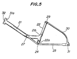
- Fig. 5 illustrates one example of a bicycle frame using the seat tube as above described.
- a single blank tube is formed by bulge-forming with a head tube portion 21a and a seat tube support portion 21b integral therewith to form a main frame 21.
- the main frame 21 it is preferable to use the method of forming frame tubes for two-wheeled vehicles developed by the applicant (Japanese Patent Application No. 39,007/80, Japanese Laid-open Patent Application No. 56-136,245) and to utilize the blank tubes for two-wheeled vehicles developed by the applicant (Japanese Patent Application No. 177,037/81).
- a single blank tube is formed at its lower end with a cross-shaped portion by bulge-forming also in the same manner as in forming the main frame 21. Horizontal extensions of the cross-shaped portion are further finished into a hanger portion or bottom bracket 22a to form the seat tube 22.
- the seat tube 22 is inserted into the seat tube support portion 21 b of the main frame 21 from its lower end and they are fixed with each other by spot welding at 23 as shown in Fig. 7.
- a metal plate is formed into a metal fitting 24 having an aperture 24a encircled by a collar adapted to be fitted within a lower end 22b of the seat tube 22 and chain stay supports 24b having a semicircular cross-section on both sides of the aperture 24a.
- the lower end 22b of the seat tube 22 is fitted within the aperture 24a of the metal fitting 24 to combine it with the seat tube 22 as shown in Figs. 9 and 10.
- Two chain stays 25 are formed in their front ends with bolt passing-through apertures 25a.
- the main frame 21 is formed at its mid portion with a bolt passing-through aperture 21c.
- Washers 36 are arranged one on each side of the aperture 21c of the main frame 21 and then the thus arranged washers 26 are embraced by the apertured front ends of the chain stays 25.
- a bolt 27 is passed through the aligned apertures 25a and 21c and tightened by a nut 28 to connect the main frame 21 and the chain stays 25.
- the chain stay supports 24b of the metal fitting 24 are located on mid portions of the chain stays 25 to determine a distance therebetween.
- Two rear forks 30 are connected at their upper ends with an upper end of the seat tube 22 through an annular band or collar 29 and at their lower ends with rear ends of the chain stays 25 by means of a connecting member 31.
- An inner tube 32 shown in Fig. 6 is inserted into the head tube portion 21a of the main frame 21 as shown in Figs. 5 and 7.
- the seat tube and frame for a bicycle according to the invention constructed as above described have the following effects.
Landscapes
- Engineering & Computer Science (AREA)
- Mechanical Engineering (AREA)
- Motorcycle And Bicycle Frame (AREA)
Description
- This invention relates to a bicycle frame comprising a main frame including a head tube portion and a seat tube support portion, wherein the seat tube is inserted in said seat tube support portion of said main frame.
- With hitherto used bicycles, as mentioned in GB-A-1070805, which corresponds to the preamble of the main claim, seat tubes and hanger portions or bottom brackets have been separately made in separate parts. After the seat tube and the bottom bracket have been integrally combined as by welding, the bottom bracket is formed in its inner surface with screw-threads with which a cup and a retainer are provided. Such a production process is, therefore, complicated to increase the production cost.
- With the prior art bicycles, moreover, there have been a great number of parts of bicycle frames. Furthermore, the parts have been combined by welding or wrapping casting (joining a member to a cast article wrapping thereabout in casting), which makes the production process complicated to lower the productivity of the bicycles. What was worse still, heating as in welding adversely affected the strength of the frame.
- It is an object of the invention to provide an improved bicycle frame, as mentioned above, which simplifies its production process avoiding thermal affecting to improve its productivity, thereby eliminating the disadvantages of the prior art.
- In order to achieve the above object, the above mentioned bicycle frame according to the invention is characterized in that said seat tube is inserted in said seat tube support portion from its lower end and has a cross-shaped lower formed from a single blank tube by bulge-forming, two lateral expanded portions of said cross-shaped lower end being used as a bottom bracket, a metal fitting having an aperture for fitting therein a lower expanded portion of said cross-shaped lower end of said seat tube and chain stay supports on both sides of said aperture, two chain stays having respective front ends abutting against and fixed to a mid portion of said main frame and respective mid portions of said chain stays abutting against said chain stay supports of said metal fitting, and rear forks connecting rear ends of said chain stays and an upper end of said seat tube. Favourable modifications of the invention may be seen in the features of the subclaims.
- The invention will be more fully understood by referring to the following detailed specification and claims taken in connection with the appended drawings.
- Fig. 1 is a perspective view of a seat tube on the way of manufacturing according to the invention;
- Fig. 2 is a perspective view of the seat tube whose two lateral expanded portions are pierced according to the invention;
- Fig. 3 is a perspective view of the seat tube provided with bearings inserted in the pierced expanded portions;
- Fig. 4 is an exploded perspective view of parts to be incorporated in the seat tube according to the invention;
- Fig. 5 is a side view of an entire bicycle frame according to the invention;
- Fig. 6 is an exploded perspective view of the bicycle frame shown in Fig. 5;
- Fig. 7 shows a front part of the bicycle frame shown in Fig. 5;
- Fig. 8 shows a rear part of the bicycle frame shown in Fig. 5;
- Fig. 9 is a perspective view of a hanger portion or bottom bracket of the bicycle frame shown in Fig. 5 as viewed from the top; and
- Fig. 10 is a perspective view of the bottom bracket shown in Fig. 5 as viewed from the bottom.
- The words "front" and "rear" used in the specification and claims mean front and rear sides as viewed from a cyclist riding on a bicycle.
- Referring to Fig. 1, a blank tube A consisting of a tube 1 having two lateral expanded
portions End plates 2a and 3a of the expandedportions apertures 5 and 6 as shown in Fig. 2. Prefabricated or commerciallyavailable bearings 7 and 8 are respectively press-fitted in theapertures 5 and 6 to form a hanger portion orbottom bracket 9 integral with the seat tube 1 as shown in Fig. 3. A reference numeral 4 denotes an urging end in the bulge-forming. It is preferable for the above bulge-forming to use the method of forming frame tubes for two-wheeled vehicles developed by the applicant (Japanese Patent Application No. 39,007/80, Japanese Laid-open Patent Application No. 56-136,245). It is also preferable for the blank tubes A to utilize the frame blank tubes for two-wheeled vehicles (Japanese Patent Application No. 177,037/81). - Fig. 4 illustrates respective members to be mounted onto the seat tube for a bicycle constructed as above described according to the invention, such as a
crankshaft 10,spring washers 11 and 12,crank arms nuts - Fig. 5 illustrates one example of a bicycle frame using the seat tube as above described. A single blank tube is formed by bulge-forming with a
head tube portion 21a and a seattube support portion 21b integral therewith to form amain frame 21. In forming themain frame 21, it is preferable to use the method of forming frame tubes for two-wheeled vehicles developed by the applicant (Japanese Patent Application No. 39,007/80, Japanese Laid-open Patent Application No. 56-136,245) and to utilize the blank tubes for two-wheeled vehicles developed by the applicant (Japanese Patent Application No. 177,037/81). - In the same manner as in making the seat tube 1, a single blank tube is formed at its lower end with a cross-shaped portion by bulge-forming also in the same manner as in forming the
main frame 21. Horizontal extensions of the cross-shaped portion are further finished into a hanger portion or bottom bracket 22a to form theseat tube 22. Theseat tube 22 is inserted into the seattube support portion 21 b of themain frame 21 from its lower end and they are fixed with each other by spot welding at 23 as shown in Fig. 7. - A metal plate is formed into a
metal fitting 24 having anaperture 24a encircled by a collar adapted to be fitted within alower end 22b of theseat tube 22 and chain stay supports 24b having a semicircular cross-section on both sides of theaperture 24a. Thelower end 22b of theseat tube 22 is fitted within theaperture 24a of themetal fitting 24 to combine it with theseat tube 22 as shown in Figs. 9 and 10. Twochain stays 25 are formed in their front ends with bolt passing-throughapertures 25a. On the other hand, themain frame 21 is formed at its mid portion with a bolt passing-through aperture 21c. Washers 36 are arranged one on each side of the aperture 21c of themain frame 21 and then the thus arrangedwashers 26 are embraced by the apertured front ends of the chain stays 25. Abolt 27 is passed through the alignedapertures 25a and 21c and tightened by anut 28 to connect themain frame 21 and the chain stays 25. The chain stay supports 24b of themetal fitting 24 are located on mid portions of the chain stays 25 to determine a distance therebetween. Tworear forks 30 are connected at their upper ends with an upper end of theseat tube 22 through an annular band orcollar 29 and at their lower ends with rear ends of the chain stays 25 by means of a connectingmember 31. Aninner tube 32 shown in Fig. 6 is inserted into thehead tube portion 21a of themain frame 21 as shown in Figs. 5 and 7. - The seat tube and frame for a bicycle according to the invention constructed as above described have the following effects.
- (1) The seat tube having the hanger portion or bottom bracket integral therewith is made of a single tube by cold-forming. Accordingly, the strength of connection between the seat tube and hanger portion or bottom bracket is much higher than that of connections by welding and the like of the prior art.
- (2) Production steps for the seat tube are simplified because the welding process as in the prior art is not needed.
- (3) The prefabricated bearings are press-fitted into lower end of the seat tube to serve as a combination of cups and retainers, so that screwthread cutting processes can be deleted to reduce the production cost.
- (4) Dimensional accuracy between the seat tube and the hanger portion or bottom bracket is improved.
- (5) The front half of the frame is produced only by inserting the
seat tube 22 into the main frame and spot welding them. Accordingly, the connection of them is simplified to improve the productivity to a great extent. - (6) The rear half of the frame is produced only by bolting the chain stays 25 and
rear forks 30 to the front half of the frame. Accordingly, the assembling is simplified to improve the productivity remarkably. In other words, the bicycle frame according to the invention can be assembled only by spot welding and bolting. - (7) The triangular construction formed by the rear portion of the
main frame 21, the lower portion of theseat tube 22 and the front portions of the chain stays 25 is very strong in construction. Accordingly, the frame according to the invention is a high strength frame as a whole. - (8) The increased constructional strength of the seat tube and the frame makes it possible to use thinner tubes for them to reduce the number of parts and hence the entire frame weight.
- (9) Although the
lower end 22b of theseat tube 22 is an urged end formed in bulge-forming the hanger portion or bottom bracket 22a, thelower end 22b serves to fit in themetal fitting 24 for supporting the chain stays 25, so that any trimming after bulge-forming is not needed. - (10) The rear half of the frame can be secured to the front half of the frame in a production step after the rear and front halves have been coated with paint or plated, and therefore it is possible to employ a new design applying two-tone color or particular plating.
Claims (5)
Applications Claiming Priority (4)
| Application Number | Priority Date | Filing Date | Title |
|---|---|---|---|
| JP57346/82 | 1982-04-08 | ||
| JP5734682A JPS58174068A (en) | 1982-04-08 | 1982-04-08 | Frame for bicycle |
| JP50574/82U | 1982-04-09 | ||
| JP5057482U JPS58153184U (en) | 1982-04-09 | 1982-04-09 | Bicycle stand frame |
Publications (3)
| Publication Number | Publication Date |
|---|---|
| EP0091655A2 EP0091655A2 (en) | 1983-10-19 |
| EP0091655A3 EP0091655A3 (en) | 1985-01-16 |
| EP0091655B1 true EP0091655B1 (en) | 1987-08-12 |
Family
ID=26391049
Family Applications (1)
| Application Number | Title | Priority Date | Filing Date |
|---|---|---|---|
| EP83103359A Expired EP0091655B1 (en) | 1982-04-08 | 1983-04-06 | Bicycle frame |
Country Status (3)
| Country | Link |
|---|---|
| US (1) | US4541648A (en) |
| EP (1) | EP0091655B1 (en) |
| DE (1) | DE3372956D1 (en) |
Cited By (1)
| Publication number | Priority date | Publication date | Assignee | Title |
|---|---|---|---|---|
| DE19602423A1 (en) * | 1996-01-24 | 1997-09-25 | Hans Schauff Fahrradfabrik | One-piece tubular tubular frame |
Families Citing this family (23)
| Publication number | Priority date | Publication date | Assignee | Title |
|---|---|---|---|---|
| DE3372956D1 (en) * | 1982-04-08 | 1987-09-17 | Bridgestone Cycle Co | Bicycle frame |
| GB2144687B (en) * | 1983-08-10 | 1987-06-24 | Michael David Strutt | Improvements in bicycle frames and bicycles |
| GB8709130D0 (en) * | 1987-04-15 | 1987-05-20 | Moulton Ltd Alex | Bicycle frame |
| EP0491363B1 (en) * | 1990-12-18 | 1994-11-30 | Bridgestone Cycle Co., Ltd. | Bicycle frame |
| USD330877S (en) | 1991-09-16 | 1992-11-10 | Schwinn Bicycle Company | Lug for a bicycle frame for connecting head tube to top tube |
| USD331378S (en) | 1991-09-16 | 1992-12-01 | Schwinn Bicycle Company | Lug for a bicycle frame for connecting seat tube to top tube |
| USD337974S (en) | 1991-09-18 | 1993-08-03 | Schwinn Bicycle Company | Lug for a bicycle frame for connecting seat tube to top tube |
| DE4142619C2 (en) * | 1991-12-21 | 1994-09-29 | Hde Metallwerk Gmbh | Bicycle frame |
| JP3269880B2 (en) * | 1993-07-02 | 2002-04-02 | 本田技研工業株式会社 | Method of manufacturing frame constituent member |
| DE4435518A1 (en) * | 1994-10-04 | 1996-04-11 | Recker & Co Gmbh J | Bicycle frame, esp. for use by ladies |
| ATE205146T1 (en) * | 1997-04-16 | 2001-09-15 | Hansmann Karl Heinz | ELECTRONIC EMERGENCY CALL AND LOCATION SYSTEM FOR RESCUE PEOPLE IN EMERGENCY |
| CN1090125C (en) * | 1997-12-18 | 2002-09-04 | 菲奥拉范蒂有限公司 | Cycle frame |
| GB2352212A (en) * | 1999-07-21 | 2001-01-24 | Atb Sales Ltd | Rear wheel mounting in a bicycle |
| US20030205882A1 (en) * | 2001-05-16 | 2003-11-06 | Parkin Michael James | Living hinge member and suspension |
| FR2829990B1 (en) * | 2001-09-27 | 2004-01-30 | Renault | BIKE FRAME |
| DE10329266A1 (en) * | 2003-06-30 | 2005-01-20 | Robert Bosch Gmbh | Windscreen wiper device, in particular for a motor vehicle |
| USD533811S1 (en) | 2006-01-03 | 2006-12-19 | Cycle Support West, Inc. | Woman's bicycle frame |
| USD533812S1 (en) | 2006-01-03 | 2006-12-19 | Cycle Support West | Men's bicycle frame |
| US20090232436A1 (en) * | 2008-03-14 | 2009-09-17 | Khe Fahrradhandels Gmbh | Bicycle bearings |
| USD662445S1 (en) | 2011-04-27 | 2012-06-26 | Mobility Holdings, Limited | Foldable bicycle frame |
| USD693739S1 (en) * | 2012-03-05 | 2013-11-19 | Mobility Holdings, Limited | Bicycle frame |
| USD690239S1 (en) * | 2012-03-05 | 2013-09-24 | Mobility Holdings, Limited | Bicycle frame |
| USD690238S1 (en) * | 2012-05-03 | 2013-09-24 | Mobility Holdings, Limited | Bicycle frame |
Family Cites Families (19)
| Publication number | Priority date | Publication date | Assignee | Title |
|---|---|---|---|---|
| CA472352A (en) * | 1951-03-20 | Northern Indiana Brass Company | Methods and apparatus for producing wrought metal fittings | |
| NL100313C (en) * | 1900-01-01 | |||
| US1449235A (en) * | 1921-06-08 | 1923-03-20 | Mead Cycle Company | Crank-hanger assembly |
| GB296539A (en) * | 1927-08-10 | 1928-09-06 | Standard Cycle Company Ltd | Improvements in or relating to the manufacture of cycle and scooter frames |
| US1914811A (en) * | 1930-12-29 | 1933-06-20 | Murray Ohio Mfg Co | Joining metal parts including tubes |
| US2183563A (en) * | 1937-08-26 | 1939-12-19 | Kenneth V Hart | Fabricated structure |
| US2353712A (en) * | 1942-07-16 | 1944-07-18 | Clarence L Dewey | Bicycle frame |
| CH237903A (en) * | 1942-12-04 | 1945-05-31 | Valat Louis | Lady's bicycle frame. |
| GB639709A (en) * | 1948-11-26 | 1950-07-05 | George Anderson Cushing | Improvements in or relating to bicycle frames |
| DE1018329B (en) * | 1953-02-09 | 1957-10-24 | Triumph Werke Nuernberg Ag | Frame for two-wheeled vehicles, especially for bicycles with an auxiliary engine |
| US3030124A (en) * | 1959-01-19 | 1962-04-17 | American Mach & Foundry | Bond joints for a bicycle frame |
| GB1070805A (en) * | 1964-11-27 | 1967-06-01 | Moulton Consultants Ltd | Improvements in and relating to frames for two wheeled cycle vehicles |
| NL6914696A (en) * | 1969-09-29 | 1971-03-31 | ||
| JPS5262841A (en) * | 1975-11-19 | 1977-05-24 | Senkichirou Kimura | Method and device for producing head lug with single unit decoration for bicycle or the like |
| US4051704A (en) * | 1975-11-19 | 1977-10-04 | Senkichiro Kimura | Method for the manufacture of an ornamental head lug of the single unit type for use in bicycles |
| JPS5933050B2 (en) * | 1980-03-28 | 1984-08-13 | ブリヂストンサイクル株式会社 | motorcycle frame |
| JPS56136245A (en) * | 1980-03-28 | 1981-10-24 | Bridgestone Cycle Co | Formation of frame pipe for bicycle |
| US4484756A (en) * | 1981-11-04 | 1984-11-27 | Bridgestone Cycle Co., Ltd. | Blank tube and main frame for two-wheeled vehicle |
| DE3372956D1 (en) * | 1982-04-08 | 1987-09-17 | Bridgestone Cycle Co | Bicycle frame |
-
1983
- 1983-04-06 DE DE8383103359T patent/DE3372956D1/en not_active Expired
- 1983-04-06 EP EP83103359A patent/EP0091655B1/en not_active Expired
- 1983-08-08 US US06/482,965 patent/US4541648A/en not_active Expired - Fee Related
Cited By (1)
| Publication number | Priority date | Publication date | Assignee | Title |
|---|---|---|---|---|
| DE19602423A1 (en) * | 1996-01-24 | 1997-09-25 | Hans Schauff Fahrradfabrik | One-piece tubular tubular frame |
Also Published As
| Publication number | Publication date |
|---|---|
| EP0091655A2 (en) | 1983-10-19 |
| US4541648A (en) | 1985-09-17 |
| DE3372956D1 (en) | 1987-09-17 |
| EP0091655A3 (en) | 1985-01-16 |
Similar Documents
| Publication | Publication Date | Title |
|---|---|---|
| US4541648A (en) | Bicycle frame | |
| US4548422A (en) | Bicycle frame having an assembled-unit shell structure | |
| EP1462351B1 (en) | Motorcycle | |
| US5129665A (en) | Bicycle frame with one or two improved wishbone stays | |
| US3233916A (en) | Velocipede frame | |
| US7377535B2 (en) | Bicycle frame | |
| US4583755A (en) | Bicycle frame | |
| US6695089B2 (en) | Motorcycle frame | |
| US20050032596A1 (en) | Bicycle sprocket | |
| US5211415A (en) | Bicycle frame with channel member | |
| US5653007A (en) | Method for producing a bicycle fork brake arch and legs assembly | |
| US20050217417A1 (en) | Bicycle crank arm | |
| EP0491363A1 (en) | Bicycle frame | |
| US20030038449A1 (en) | Bicycle fork and pivot for same | |
| US4230245A (en) | Parcel carriers for motor cycles | |
| US6412879B1 (en) | Composite spring seat for an axle housing | |
| JP7718192B2 (en) | Front fender | |
| CA2480829C (en) | Balance weight and balance-correcting structure for spoke wheel | |
| US2798739A (en) | Knockdown bicycle construction | |
| EP2383174B1 (en) | Saddle-Riding Vehicle | |
| JPH0144555B2 (en) | ||
| GB2085378A (en) | Cycle frames | |
| US2470441A (en) | Bicycle frame | |
| JPS581099Y2 (en) | Crossbar structure of frames of motorcycles, etc. | |
| EP0780285A1 (en) | Motor vehicle frame |
Legal Events
| Date | Code | Title | Description |
|---|---|---|---|
| PUAI | Public reference made under article 153(3) epc to a published international application that has entered the european phase |
Free format text: ORIGINAL CODE: 0009012 |
|
| AK | Designated contracting states |
Designated state(s): DE FR GB IT NL |
|
| PUAL | Search report despatched |
Free format text: ORIGINAL CODE: 0009013 |
|
| AK | Designated contracting states |
Designated state(s): DE FR GB IT NL |
|
| 17P | Request for examination filed |
Effective date: 19850314 |
|
| 17Q | First examination report despatched |
Effective date: 19860321 |
|
| ITF | It: translation for a ep patent filed | ||
| GRAA | (expected) grant |
Free format text: ORIGINAL CODE: 0009210 |
|
| AK | Designated contracting states |
Kind code of ref document: B1 Designated state(s): DE FR GB IT NL |
|
| REF | Corresponds to: |
Ref document number: 3372956 Country of ref document: DE Date of ref document: 19870917 |
|
| ET | Fr: translation filed | ||
| PLBE | No opposition filed within time limit |
Free format text: ORIGINAL CODE: 0009261 |
|
| STAA | Information on the status of an ep patent application or granted ep patent |
Free format text: STATUS: NO OPPOSITION FILED WITHIN TIME LIMIT |
|
| 26N | No opposition filed | ||
| PGFP | Annual fee paid to national office [announced via postgrant information from national office to epo] |
Ref country code: GB Payment date: 19930402 Year of fee payment: 11 |
|
| PG25 | Lapsed in a contracting state [announced via postgrant information from national office to epo] |
Ref country code: GB Effective date: 19940406 |
|
| PGFP | Annual fee paid to national office [announced via postgrant information from national office to epo] |
Ref country code: DE Payment date: 19940429 Year of fee payment: 12 |
|
| PGFP | Annual fee paid to national office [announced via postgrant information from national office to epo] |
Ref country code: NL Payment date: 19940430 Year of fee payment: 12 |
|
| GBPC | Gb: european patent ceased through non-payment of renewal fee |
Effective date: 19940406 |
|
| PG25 | Lapsed in a contracting state [announced via postgrant information from national office to epo] |
Ref country code: NL Effective date: 19951101 |
|
| NLV4 | Nl: lapsed or anulled due to non-payment of the annual fee |
Effective date: 19951101 |
|
| PG25 | Lapsed in a contracting state [announced via postgrant information from national office to epo] |
Ref country code: DE Effective date: 19960103 |
|
| PGFP | Annual fee paid to national office [announced via postgrant information from national office to epo] |
Ref country code: FR Payment date: 19960425 Year of fee payment: 14 |
|
| PG25 | Lapsed in a contracting state [announced via postgrant information from national office to epo] |
Ref country code: FR Free format text: LAPSE BECAUSE OF NON-PAYMENT OF DUE FEES Effective date: 19971231 |
|
| REG | Reference to a national code |
Ref country code: FR Ref legal event code: ST |