EP0091530A1 - Safety ski binding - Google Patents
Safety ski binding Download PDFInfo
- Publication number
- EP0091530A1 EP0091530A1 EP82420099A EP82420099A EP0091530A1 EP 0091530 A1 EP0091530 A1 EP 0091530A1 EP 82420099 A EP82420099 A EP 82420099A EP 82420099 A EP82420099 A EP 82420099A EP 0091530 A1 EP0091530 A1 EP 0091530A1
- Authority
- EP
- European Patent Office
- Prior art keywords
- ski
- boot
- pivot axis
- shoe
- axis
- Prior art date
- Legal status (The legal status is an assumption and is not a legal conclusion. Google has not performed a legal analysis and makes no representation as to the accuracy of the status listed.)
- Granted
Links
Images


Classifications
-
- A—HUMAN NECESSITIES
- A63—SPORTS; GAMES; AMUSEMENTS
- A63C—SKATES; SKIS; ROLLER SKATES; DESIGN OR LAYOUT OF COURTS, RINKS OR THE LIKE
- A63C9/00—Ski bindings
- A63C9/08—Ski bindings yieldable or self-releasing in the event of an accident, i.e. safety bindings
- A63C9/086—Ski bindings yieldable or self-releasing in the event of an accident, i.e. safety bindings using parts which are fixed on the shoe of the user and are releasable from the ski binding
-
- A—HUMAN NECESSITIES
- A63—SPORTS; GAMES; AMUSEMENTS
- A63C—SKATES; SKIS; ROLLER SKATES; DESIGN OR LAYOUT OF COURTS, RINKS OR THE LIKE
- A63C9/00—Ski bindings
- A63C9/08—Ski bindings yieldable or self-releasing in the event of an accident, i.e. safety bindings
- A63C9/081—Ski bindings yieldable or self-releasing in the event of an accident, i.e. safety bindings with swivel sole-plate
-
- A—HUMAN NECESSITIES
- A63—SPORTS; GAMES; AMUSEMENTS
- A63C—SKATES; SKIS; ROLLER SKATES; DESIGN OR LAYOUT OF COURTS, RINKS OR THE LIKE
- A63C9/00—Ski bindings
- A63C9/08—Ski bindings yieldable or self-releasing in the event of an accident, i.e. safety bindings
- A63C9/085—Ski bindings yieldable or self-releasing in the event of an accident, i.e. safety bindings with sole hold-downs, e.g. swingable
- A63C9/08535—Ski bindings yieldable or self-releasing in the event of an accident, i.e. safety bindings with sole hold-downs, e.g. swingable with a mobile body or base or single jaw
- A63C9/08542—Ski bindings yieldable or self-releasing in the event of an accident, i.e. safety bindings with sole hold-downs, e.g. swingable with a mobile body or base or single jaw pivoting about a transversal axis
-
- A—HUMAN NECESSITIES
- A63—SPORTS; GAMES; AMUSEMENTS
- A63C—SKATES; SKIS; ROLLER SKATES; DESIGN OR LAYOUT OF COURTS, RINKS OR THE LIKE
- A63C9/00—Ski bindings
- A63C9/08—Ski bindings yieldable or self-releasing in the event of an accident, i.e. safety bindings
- A63C9/085—Ski bindings yieldable or self-releasing in the event of an accident, i.e. safety bindings with sole hold-downs, e.g. swingable
- A63C9/08557—Details of the release mechanism
- A63C9/08564—Details of the release mechanism using cam or slide surface
-
- A—HUMAN NECESSITIES
- A63—SPORTS; GAMES; AMUSEMENTS
- A63C—SKATES; SKIS; ROLLER SKATES; DESIGN OR LAYOUT OF COURTS, RINKS OR THE LIKE
- A63C9/00—Ski bindings
- A63C9/08—Ski bindings yieldable or self-releasing in the event of an accident, i.e. safety bindings
- A63C9/085—Ski bindings yieldable or self-releasing in the event of an accident, i.e. safety bindings with sole hold-downs, e.g. swingable
- A63C9/08557—Details of the release mechanism
- A63C9/08578—Details of the release mechanism using a plurality of biasing elements
-
- A—HUMAN NECESSITIES
- A63—SPORTS; GAMES; AMUSEMENTS
- A63C—SKATES; SKIS; ROLLER SKATES; DESIGN OR LAYOUT OF COURTS, RINKS OR THE LIKE
- A63C9/00—Ski bindings
- A63C9/20—Non-self-releasing bindings with special sole edge holders instead of toe-straps
Definitions
- the present invention relates to a device for attaching a boot to a ski and more particularly a safety binding intended for the practice of cross-country skiing.
- the binding is arranged mobile in rotation on the ski around a true vertical axis of articulation or around a virtual axis, materialized by a projecting profile cooperating with a hollow profile.
- the pivot axis is either placed under the front end of the shoe, as in FIG. 1 of the drawings, or well in front of the latter, as in FIG. 2. Although representing progress, this particular position of the pivot is not correct and even has serious drawbacks.
- the present invention aims to remedy the drawbacks described above by placing the pivot axis at the level of the plantar support.
- the pivot axis at the level of the plantar support.
- FIG. 1 to 3 we recognize, in top view, a ski 1 with the outer contour of a shoe 2 in which is sketched a foot 3 and the support area 4 of this foot 3 in the shoe 2.
- This support zone represented by its outer contour, shown in gray and corresponding to the position of the boot 2 flat on the ski 1 (heel not lifted), is that in which the significant forces are exerted between the foot 3 of the skier and shoe 2.
- the resulting lateral force F is exerted in the region of the plantar support as represented.
- this force F is completely normal, and presenting no danger to the skier, any triggering of the safety binding (not shown) binding the boot 2 to the ski 1, due to the presence of this effort F is untimely and should therefore be avoided.
- FIG. 1 belongs to a state of the art, for example that which corresponds to the application DE-A-2907365 and to the utility model DE GM 7723934 and in which the fixing (not shown) between the shoe 2 and the ski 1 is articulated in rotation in the plane of the ski 1 around a vertical pivot axis 5 located just in front of the toe 3, or approximately under the front end of the boot 2.
- a distance 1 separates this pivot axis 5 of the point of application of the resulting lateral force F and a torsional moment F1 is therefore exerted on the fastening.
- this fastening is normally maintained in the centered position by a locking system, triggerable as soon as the torsional moment which is exerted on it exceeds a certain threshold.
- FIG. 2 which illustrates for example the state of the art represented by the patent application FR 8100358 is even more critical.
- the conditions are the same as above with the exception of point 5 which is well in front of the anterior end of shoe 2.
- the torsional moment FI being much greater than that of the previous case, the disadvantages which we have just see are therefore amplified in their effects.
- FIG. 3 illustrates the principle of the invention which, by locating the vertical pivot axis 5 in the plantar support area 4 of the skier's foot 3, and more precisely at the point of application of the resulting force F, or in its immediate vicinity, cancels or at least makes the torsional moment F negligible, by the disappearance of the lever arm 1.
- the lateral force F generated by the duck walk will have no influence on the triggering of the associated safety binding, whatever its type as regards the means of attachment of the shoe as well as those of locking and triggering in torsion.
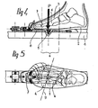
- FIGs 4 and 5 show a practical embodiment of the invention corresponding to that which is described with reference to Figures 8 to 11 of French patent application 8206434 of 04.04.1982 and whose priority is claimed for this application .
- the binding of the boot 2 to the ski 1 is of the type described in application FR No. 2,447,731 and it is therefore unnecessary to return to it.
- the skeleton of the foot 3 is represented with the metatarsals 6 and the phalangins 7 under which the plantar support zone 4 develops.
- the vertical result of this support is represented by the arrow P (FIG. 5).
- the pivot 5 connecting the plate 8 to the ski 1, as in the priority request mentioned, is placed in the axis of the ski 1 in the plantar support zone 4.
- the pivot 5 will preferably be placed at the intersection of the axis 9 of this articulation and the longitudinal axis of the ski 1.
- FIGS. 6 and 7 illustrate in an analogous manner an exemplary embodiment of the invention in relation to a safety attachment of the type described in the utility model DE-GM-7723934 and the description of which here would therefore be superfluous, for this close that the pivot 5 is arranged according to the present invention and no longer under the front of the shoe as in Figure 1.
- the same elements bear in Figures 6 and 7 the same references as in the previous case.
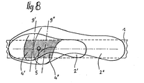
- the pivot 5 is arranged in the part common to the plantar support zones 4 ′ and 4 "corresponding respectively to a shoe of small size 2 'and a shoe of large size 2 ", and according to a preferred embodiment halfway between the axes of metatarsophalangeal articulation 9' and 9".
- the position of the pivot can be adjustable within a certain range along the longitudinal axis of the ski, for example by a device with screw, which does not pose any particular additional problem to those skilled in the art.
Abstract
Description
La présente invention concerne un dispositif de fixation d'une chaussure à un ski et plus particulièrement une fixation de sécurité destinée à la pratique du ski de fond.The present invention relates to a device for attaching a boot to a ski and more particularly a safety binding intended for the practice of cross-country skiing.
On connaît de très nombreux dispositifs destinés à maintenir l'extrémité avant de la chaussure sur le ski tout en autorisant au moins la levée du talon pendant la phase de la marche. Le seul mouvement possible de la chaussure est alors cette levée du talon pour permettre la marche. Pour assurer un bon guidage du ski dans la trace lors de la marche, le maintien avant de la chaussure doit être suffisamment rigide. Plus le maintien dans le sens latéral du pied par rapport au ski est élevé, plus la conduite du ski est précise, mais cela n'est pas sans inconvénients. Il y a en effet de gros risques pour la jambe du skieur qui ne possède pas nécessairement un niveau sportif et technique très élevé pour pratiquer avec le maximum d'aisance et de sécurité et qui peut se trouver dans des positions où le mouvement en torsion par rapport au ski, du pied, est absolument nécessaire pour éviter une fracture.Many devices are known for holding the front end of the boot on the ski while at least allowing the heel to be lifted during the walking phase. The only possible movement of the shoe is then this lifting of the heel to allow walking. To ensure proper guidance of the ski in the track during walking, the front support of the boot must be sufficiently rigid. The higher the support in the lateral direction of the foot relative to the ski, the more precise the handling of the ski is, but this is not without drawbacks. There are indeed big risks for the skier's leg which does not necessarily have a very high sporting and technical level to practice with maximum ease and security and which can be in positions where the movement in torsion by ski, foot, is absolutely necessary to avoid a fracture.
Certains constructeurs ont alors pensé à faire déclencher en sécurité la fixation.Some manufacturers have therefore thought of triggering the binding securely.
Il peut y avoir libération pure et simple de la chaussure par rapport au ski, ou encore uniquement une possibilité de torsion de la chaussure par rapport au ski sans libération. On peut ainsi citer la demande de brevet allemand 29 07 365, le modèle d'utilité allemand 77 23 934, ainsi que la demande de brevet français 81 00 358.There may be outright release of the boot relative to the ski, or even only a possibility of torsion of the boot relative to the ski without release. We can thus cite the German patent application 29 07 365, the German utility model 77 23 934, as well as the French patent application 81 00 358.
Selon différents modes de réalisation, la fixation est disposée mobile en rotation sur le ski autour d'un véritable axe vertical d'articulation ou autour d'un axe virtuel, matérialisé par un profil en saillie coopérant avec un profil en creux. On constate que l'axe de pivotement est soit placé sous l'extrémité avant de la chaussure , comme à la figure 1 des dessins, soit bien en avant de celle-ci, comme à la figure 2. Bien que représentant un progrès, cette position particulière du pivot n'est pas correcte et présente même de graves inconvénients. En effet, pendant la pratique du ski et notamment lors de la phase de propulsion ou lors d'une marche en canard, voire même lors d'une descente, l'action de la chaussure développe au niveau de l'appui plantaire un effort qui, distant du pivot, fournit un moment de torsion qui peut provoquer la rotation et le déclenchement de la fixation alors que la jambe n'est pas en danger. Il y aura donc des déclenchements intempestifs et le skieur, pour améliorer la skiabilité, sera amené à augmenter la valeur du seuil de déclenchement des verrouillages. Mais il aura ainsi diminué sa sécurité jusqu'à même la rendre parfaitement inefficace dans les conditions où elle serait nécessaire.According to different embodiments, the binding is arranged mobile in rotation on the ski around a true vertical axis of articulation or around a virtual axis, materialized by a projecting profile cooperating with a hollow profile. It can be seen that the pivot axis is either placed under the front end of the shoe, as in FIG. 1 of the drawings, or well in front of the latter, as in FIG. 2. Although representing progress, this particular position of the pivot is not correct and even has serious drawbacks. Indeed, during skiing, especially during the propulsion phase or during a duck walk, or even during a descent, the action of the shoe develops at the level of the plantar support an effort which, distant from the pivot, provides a moment of torsion which can cause rotation and the release of the fixation while the leg is not in danger. There will therefore be untimely triggers and the skier, to improve skiability, will have to increase the value of the threshold for triggering interlocks. But it will thus have reduced its security to the point of even rendering it perfectly ineffective under the conditions where it would be necessary.
La présente invention vise à remédier aux inconvénients décrits ci-dessus en plaçant l'axe de pivotement au niveau de l'appui plantaire. Ainsi, lors de la pratique du ski, la force résultante exercée par la chaussure sur la fixation passera par l'axe de pivotement et, le moment de torsion étant nul ou négligeable, aucun déclenchement intempestif n'interviendra. Ce n'est que dans le cas d'une chute ou d'une torsion excessive que le déclenchement aura lieu, assurant ainsi la sécurité effective du skieur.The present invention aims to remedy the drawbacks described above by placing the pivot axis at the level of the plantar support. Thus, when skiing, the resulting force exerted by the boot on the binding will pass through the pivot axis and, the torsional moment being zero or negligible, no untimely triggering will occur. It is only in the event of a fall or excessive torsion that the release will take place, thus ensuring the effective safety of the skier.
L'invention sera mieux comprise à la lumière de la description qui suit et pour l'intelligence de laquelle on se référera aux dessins dont :
- - les figures 1 et 2 illustrent, en vue de dessus, respectivement les inconvénients de l'état connu de la technique,
- - la figure 3, selon le même mode de représentation, met en évidence la solution théorique selon l'invention,
- - les figures 4 et 5 montrent respectivement en coupe longitudinale et vue de dessus un mode de réalisation pratique de l'invention,
- - les figures 6 et 7 montrent de même un autre mode d'exécution, et
- - la figure 8 montre la zone de localisation de l'axe de pivotement selon l'invention qu'il est avantageux d'adopter pour l'utiliser avec différentes pointures de chaussures.
- FIGS. 1 and 2 illustrate, in plan view, respectively the drawbacks of the known state of the art,
- FIG. 3, according to the same mode of representation, highlights the theoretical solution according to the invention,
- FIGS. 4 and 5 show respectively in longitudinal section and top view a practical embodiment of the invention,
- FIGS. 6 and 7 likewise show another embodiment, and
- - Figure 8 shows the location of the pivot axis according to the invention which it is advantageous to adopt for use with different shoe sizes.
Aux figures 1 à 3, on reconnaît, en vue de dessus, un ski 1 avec le contour extérieur d'une chaussure 2 dans lequel est esquissé un pied 3 et la zone d'appui 4 de ce pied 3 dans la chaussure 2. Cette zone d'appui, représentée par son contour extérieur, figurée en grisé et correspondant à la position de la chaussure 2 à plat sur le ski 1 (talon non levé), est celle dans laquelle s'exercent les efforts significatifs entre le pied 3 du skieur et la chaussure 2. Dans le cas par exemple d'un mouvement de marche en canard et de situations similaires, l'effort latéral résultant F s'exerce dans la région de l'appui plantaire comme représenté. Comme il a été dit dans l'introduction, cet effort F est tout à fait normal, et ne présentant aucun danger pour le skieur, tout déclenchement de la fixation de sécurité (non représentée) liant la chaussure 2 au ski 1, dû à la présence de cet effort F est intempestif et devrait donc être évité.Figures 1 to 3, we recognize, in top view, a
Le cas de la figure 1 appartient à un état de la technique, par exemple celui qui correspond à la demande DE-A-2907365 et au modèle d'utilité DE GM 7723934 et dans lequel la fixation (non représentée) entre la chaussure 2 et le ski 1 est articulée en rotation dans le plan du ski 1 autour d'un axe de pivotement vertical 5 situé juste devant la pointe du pied 3, soit à peu près sous l'extrémité avant de la chaussure 2. Une distance 1 sépare cet axe de pivotement 5 du point d'application de l'effort latéral résultant F et un moment de torsion F1 s'exerce donc sur la fixation.Comme connu, cette fixation est normalement maintenue en position centrée par un système de verrouillage, déclenchable dès que le moment de torsion qui s'exerce sur lui dépasse un certain seuil. Dans la disposition représentée, lors d'une marche en canard un peu rapide, ou dans d'autres conditions tout à fait normales de pratique du ski, le moment de torsion FI peut aisément dépasser le seuil et provoquer un déclenchement intempestif (figuré en traits interrompus), ce qui amène souvent le skieur à "durcir", c'est-à-dire à élever le seuil de déclenchement de sa fixation pour éviter d'avoir à intervenir trop souvent. Comme déjà dit plus haut, en agissant ainsi, il rend sa fixation inefficace également pour les conditions dans lesquelles le déclenchement est nécessaire pour la sécurité du skieur.The case of FIG. 1 belongs to a state of the art, for example that which corresponds to the application DE-A-2907365 and to the utility model DE GM 7723934 and in which the fixing (not shown) between the
Le cas de la figure 2 qui illustre par exemple l'état de la technique représenté par la demande de brevet FR 8100358 est encore plus critique. Les conditions sont les mêmes que précédemment à l'exception du point 5 qui se trouve bien en avant de l'extrémité antérieure de la chaussure 2. Le moment de torsion FI étant bien supérieur à celui du cas précédent, les inconvénients que nous venons de voir sont donc amplifiés dans leurs effets.The case of FIG. 2 which illustrates for example the state of the art represented by the patent application FR 8100358 is even more critical. The conditions are the same as above with the exception of
La figure 3 illustre le principe de l'invention qui, en localisant l'axe de pivotement vertical 5 dans la zone d'appui plantaire 4 du pied 3 du skieur, et plus précisément au point d'application de l'effort résultant F, ou à son voisinage immédiat, annule ou tout au moins rend négligeable le moment de torsion F, par la disparition du bras de levier 1. Ainsi dans les mêmes conditions que précédemment, l'effort latéral F engendré par la marche en canard n'aura aucune influence sur le déclenchement de la fixation de sécurité associée, et ce quel que soit son type en ce qui concerne les moyens d'accrochage de la chaussure ainsi que ceux de verrouillage et déclenchement en torsion.FIG. 3 illustrates the principle of the invention which, by locating the
Les figures 4 et 5 représentent un mode d'exécution pratique de l'invention correspondant à celui qui est décrit en référence aux figures 8 à 11 de la demande de brevet français 8206434 du 08.04.1982 et dont la priorité est revendiquée pour la présente demande. La fixation de la chaussure 2 au ski 1 est du type décrit dans la demande FR n° 2 447 731 et il n'est donc pas utile d'y revenir. Pour la compréhension, le squelette du pied 3 est figuré avec les métatarsiens 6 et les phalangines 7 sous lesquels se développe la zone d'appui plantaire 4. La résultante verticale de cet appui est figurée par la flèche P (figure 5). Le pivot 5 liant la plaque 8 au ski 1, comme dans la demande prioritaire évoquée, est placé dans l'axe du ski 1 dans la zone d'appui plantaire 4. Comme par ailleurs, il a été constaté que la résultante P s'exerce au niveau de l'articulation métatarso-phalangienne 9 entre le métatarse 6 et les phalangines 7, figurée par le trait interrompu 9, le pivot 5 sera de préférence disposé à l'intersection de l'axe 9 de cette articulation et de l'axe longitudinal du ski 1.Figures 4 and 5 show a practical embodiment of the invention corresponding to that which is described with reference to Figures 8 to 11 of French patent application 8206434 of 04.04.1982 and whose priority is claimed for this application . The binding of the
Les figures 6 et 7 illustrent de manière analogue un exemple d'exécution de l'invention en relation avec une fixation de sécurité du type exposé dans le modèle d'utilité DE-GM-7723934 et dont la description ici serait donc superflue, à ceci près que le pivot 5 est disposé selon la présente invention et non plus sous l'avant de la chaussure comme à la figure 1. Les mêmes éléments portent aux figures 6 et 7 les mêmes références que dans le cas précédent.FIGS. 6 and 7 illustrate in an analogous manner an exemplary embodiment of the invention in relation to a safety attachment of the type described in the utility model DE-GM-7723934 and the description of which here would therefore be superfluous, for this close that the
Les exemples de réalisation en combinaison avec d'autres fixations de sécurité pourraient être multipliés, l'invention pouvant être mise en oeuvre avec tout type de fixation connu.The exemplary embodiments in combination with other safety fasteners could be multiplied, the invention being able to be implemented with any known type of fastening.
L'axe de l'articulation métatarso-phalangienne 9 ayant évidemment une position variable par rapport au ski en fonction de la pointure du skieur, il a semblé judicieux de réaliser un dispositif unique convenant à toutes les pointures en acceptant que le pivot 5 puisse être légèrement décalé par rapport à l'axe de l'articulation 9 tout en restant cependant dans son voisinage immédiat pour que le bras de levier 1 (figures 1 et 2) à défaut d'être nul reste très faible, et que le moment de torsion Fl reste insuffisant pour provoquer un déclenchement intempestif dans les conditions normales de la pratique du ski évoquées plus haut. A cet effet, comme l'illustre la figure 8 dans le mode de représentation adopté pour les figures 1 à 3, le pivot 5 est disposé dans la partie commune aux zones d'appui plantaire 4' et 4" correspondant respectivement à une chaussure de petite pointure 2' et une chaussure de grande pointure 2", et selon un mode d'exécution préférentiel à mi-chemin entre les axes d'articulation métatarso-phalangienne 9' et 9". On voit ainsi que dans tous les cas, des résultats satisfaisants pourront être obtenus et que le skieur, quelle que soit sa pointure n'aura pas à durcir le verrouillage de sa fixation de sécurité au point de lui enlever toute son efficacité.The axis of the
Dans le même ordre d'idée, pour l'utilisation optimale de l'invention quelle que soit la pointure, la position du pivot peut être réglable dans une certaine plage le long de l'axe longitudinal du ski, par exemple par un dispositif à vis, ce qui ne pose pas de problème particulier supplémentaire à l'homme de métier.In the same vein, for the optimal use of the invention whatever the size, the position of the pivot can be adjustable within a certain range along the longitudinal axis of the ski, for example by a device with screw, which does not pose any particular additional problem to those skilled in the art.
Claims (5)
Priority Applications (3)
| Application Number | Priority Date | Filing Date | Title |
|---|---|---|---|
| AT82420099T ATE23950T1 (en) | 1982-04-08 | 1982-07-13 | SAFETY SKI BINDING. |
| NO832511A NO151993C (en) | 1982-07-13 | 1983-07-11 | DEVICE FOR FITTING A SHOT TOY TO A SKI |
| US06/513,101 US4676522A (en) | 1982-07-13 | 1983-07-12 | Safety binding for a ski boot |
Applications Claiming Priority (2)
| Application Number | Priority Date | Filing Date | Title |
|---|---|---|---|
| FR8206434A FR2524812B1 (en) | 1982-04-08 | 1982-04-08 | SAFETY FIXING DEVICE FOR CROSS-COUNTRY SKIING |
| FR8206434 | 1982-04-08 |
Publications (2)
| Publication Number | Publication Date |
|---|---|
| EP0091530A1 true EP0091530A1 (en) | 1983-10-19 |
| EP0091530B1 EP0091530B1 (en) | 1986-12-03 |
Family
ID=9273021
Family Applications (1)
| Application Number | Title | Priority Date | Filing Date |
|---|---|---|---|
| EP82420099A Expired EP0091530B1 (en) | 1982-04-08 | 1982-07-13 | Safety ski binding |
Country Status (9)
| Country | Link |
|---|---|
| US (2) | US4928988A (en) |
| EP (1) | EP0091530B1 (en) |
| AT (1) | ATE23950T1 (en) |
| CH (1) | CH655669B (en) |
| DE (2) | DE3274523D1 (en) |
| FI (1) | FI77159C (en) |
| FR (1) | FR2524812B1 (en) |
| NO (1) | NO154484C (en) |
| SE (1) | SE448521B (en) |
Cited By (3)
| Publication number | Priority date | Publication date | Assignee | Title |
|---|---|---|---|---|
| DE3245668A1 (en) * | 1982-12-09 | 1984-06-14 | Geze Gmbh, 7250 Leonberg | Triggering cross-country skiing |
| DE3405861A1 (en) * | 1983-12-16 | 1985-06-27 | Geze Gmbh, 7250 Leonberg | Binding for cross-country ski |
| FR2595952A1 (en) * | 1986-03-19 | 1987-09-25 | Salomon Sa | Device for retaining the front part of a boot on a ski, particularly a cross-country ski |
Families Citing this family (22)
| Publication number | Priority date | Publication date | Assignee | Title |
|---|---|---|---|---|
| NO151993C (en) * | 1982-07-13 | 1985-07-17 | Salomon & Fils F | DEVICE FOR FITTING A SHOT TOY TO A SKI |
| FR2589362B1 (en) * | 1985-10-30 | 1988-07-08 | Salomon Sa | SECURITY FIXING FOR CROSS-COUNTRY SKIING |
| FR2590131B1 (en) * | 1985-11-15 | 1988-06-24 | Salomon Sa | DEVICE FOR LATERAL GUIDANCE AND SUPPORT OF A FIXED SHOE, AT ITS FRONT END, ON A CROSS-COUNTRY SKI |
| FR2599985B1 (en) * | 1986-03-19 | 1989-07-28 | Salomon Sa | ASSEMBLY CONSISTING OF A CROSS-COUNTRY OR HIKING SKI BOOT AND A DEVICE FOR HOLDING THE FRONT OF THIS BOOT ON A SKI |
| FR2645758B1 (en) * | 1989-04-12 | 1991-06-14 | Salomon Sa | DEVICE FOR ATTACHING A SHOE TO A CROSS-COUNTRY SKI |
| DE4142390C2 (en) * | 1991-08-05 | 1994-03-10 | Silvretta Sherpas Sportartikel | Safety binding for jump skis |
| DE4143410C2 (en) * | 1991-12-20 | 1995-06-29 | Silvretta Sherpas Sportartikel | Security binding |
| DE4142434A1 (en) * | 1991-12-20 | 1993-06-24 | Silvretta Sherpas Sportartikel | Two=part ski-binding esp. for ski jumping - has base ski-fixed part, and detachable part with release mechanism, tensioning piece, guide jaw, lever, and guide rollers |
| US5803480A (en) * | 1993-05-27 | 1998-09-08 | Rottefella S.A. | Ski-binding arrangement to fix a ski boot to a ski, in particular a touring or cross-country ski |
| DE4406074C1 (en) * | 1994-02-24 | 1995-04-20 | F2 Int Gmbh | Safety binding for snowboards |
| AUPO043296A0 (en) | 1996-06-14 | 1996-07-04 | Griplock Pty Limited | Skateboard and surfboard binding |
| US6105994A (en) * | 1997-04-09 | 2000-08-22 | Parris; James E. | Step-in binding having safety release mechanism for Telemark ski |
| US6623027B1 (en) * | 1998-06-15 | 2003-09-23 | Bryce Wheeler | Release binding and brake for telemark and cross-country skis |
| US6322095B1 (en) * | 1998-06-15 | 2001-11-27 | Bryce Wheeler | Release binding for telemark and cross-country skis |
| AUPP590198A0 (en) | 1998-09-14 | 1998-10-08 | Griplock Pty Limited | Sporting equipment binding apparatus |
| AT3309U1 (en) * | 1999-02-05 | 2000-01-25 | Atomic Austria Gmbh | PANEL-SHAPED SUPPORT ELEMENT, IN PARTICULAR FOR A SKI BINDING |
| FR2803533B1 (en) * | 2000-01-07 | 2002-04-05 | Look Fixations Sa | SUPPORT DEVICE FOR THE FRONT OF A SKI SHOE ON A SKI |
| US7458598B2 (en) * | 2005-12-05 | 2008-12-02 | Jeffrey Giffin | Telemark binding with releasable riser plate assembly |
| FR2929531B3 (en) * | 2008-04-08 | 2010-08-13 | Salomon Sas | ASSEMBLY COMPRISING A SLIDING BOARD AND A RETAINING DEVICE FOR A FOOTWEAR ARTICLE. |
| EP2135645B1 (en) * | 2008-06-19 | 2015-10-07 | Rottefella AS | Dismountable ski binding |
| DE102010040928A1 (en) * | 2010-09-16 | 2012-03-22 | Salewa Sport Ag | Gleitbrettbindung, especially touring ski binding |
| US9259343B2 (en) | 2012-07-06 | 2016-02-16 | Newman Technologies LLC | Device for mitigating plantar fasciitis |
Citations (7)
| Publication number | Priority date | Publication date | Assignee | Title |
|---|---|---|---|---|
| FR806551A (en) * | 1936-05-16 | 1936-12-19 | Ski safety tie | |
| FR890005A (en) * | 1944-03-08 | 1944-01-26 | Ski attachment | |
| FR1011091A (en) * | 1949-06-13 | 1952-06-18 | Safety binding device for skis | |
| DE7723934U1 (en) * | 1977-08-01 | 1977-11-17 | Kurz, Anton, Ing.(Grad.), 7994 Langenargen | Cross-country safety ski bindings |
| DE2907365A1 (en) * | 1979-02-24 | 1980-08-28 | Ver Baubeschlag Gretsch Co | Long distance safety ski binding - includes binding section tensioning ski-boot sole with bearing assembly rotating under torsion forces |
| FR2447731A1 (en) * | 1979-01-31 | 1980-08-29 | Salomon & Fils F | DEVICE FOR CONNECTING A SHOE WITH A SKI, PARTICULARLY FOR CROSS-COUNTRY SKIING |
| FR2497595A1 (en) * | 1981-01-06 | 1982-07-09 | Salomon & Fils F |
Family Cites Families (28)
| Publication number | Priority date | Publication date | Assignee | Title |
|---|---|---|---|---|
| US1815168A (en) * | 1930-10-06 | 1931-07-21 | Goldwin S Sprague | Ski binding |
| US2108167A (en) * | 1936-06-20 | 1938-02-15 | Gerber Sidney | Ski binding |
| US2245850A (en) * | 1940-09-06 | 1941-06-17 | Stanley C Brown | Safety binding |
| US2545574A (en) * | 1948-11-08 | 1951-03-20 | Glenn L French | Releasable ski binding |
| FR1166145A (en) * | 1957-02-01 | 1958-11-03 | Ski safety binding | |
| DE1243066B (en) * | 1961-02-06 | 1967-06-22 | Ludwig Berchtold | Swivel plate for safety ski bindings |
| FR1313684A (en) * | 1961-02-06 | 1962-12-28 | Safety binding for skis | |
| DE1728485A1 (en) * | 1964-01-14 | 1973-07-19 | Marker Hannes | SAFETY SKI BINDING FOR DOWNHILL AND TOURING |
| DE1808195A1 (en) * | 1968-11-11 | 1970-05-27 | Gustav Mueck | Ski safety binding |
| DD81815A3 (en) * | 1970-03-02 | 1971-05-05 | ||
| US3731945A (en) * | 1970-05-22 | 1973-05-08 | R Johnson | Safety ski binding apparatus |
| FR2120468A5 (en) * | 1971-01-04 | 1972-08-18 | Wunder Kg Heinrich | |
| US4629208A (en) * | 1971-05-04 | 1986-12-16 | Tmc Corporation | Safety ski binding |
| CH536644A (en) * | 1971-11-17 | 1973-05-15 | Gertsch Ag | Safety ski binding |
| DE3024592A1 (en) * | 1972-03-20 | 1982-01-28 | Albert Dipl.-Ing. 7000 Stuttgart Herrmann | Adjustable downhill and touring ski binding - includes intermediate binding section insertable between front and heel jaws |
| DE2316627A1 (en) * | 1972-04-17 | 1973-10-25 | Gertsch Ag | RELEASE SKI BINDING |
| DE2307365A1 (en) * | 1973-02-15 | 1974-08-29 | Lautenschlaeger Kg Karl | CLOSING SPRING HINGE |
| AT317739B (en) * | 1972-07-14 | 1974-09-10 | Smolka & Co Wiener Metall | Ski binding |
| DE2449793A1 (en) * | 1974-10-19 | 1976-04-22 | Helmut Schroeter | SAFETY TOURING SKI BINDING |
| DE2600899A1 (en) * | 1975-01-28 | 1976-07-29 | Jean Joseph Alfred Beyl | SKI SAFETY BINDING |
| FR2341327A1 (en) * | 1976-02-18 | 1977-09-16 | Beyl Jean Joseph Alfred | SKI BINDING WITH A MOBILE PLATE INTENDED TO RECEIVE THE CORRESPONDING SHOE |
| AT354319B (en) * | 1977-04-06 | 1980-01-10 | Tyrolia Freizeitgeraete | SAFETY SKI BINDING |
| FR2443853A1 (en) * | 1978-12-11 | 1980-07-11 | Salomon & Fils F | Ski-boot with longitudinal guiding groove in sole - is intended for cross country skiing and allows sole to flex freely |
| FR2450618B2 (en) * | 1978-12-11 | 1985-07-05 | Salomon & Fils F | ASSEMBLY FOR FIXING A SHOE TO A SKI |
| FR2447209A1 (en) * | 1979-01-26 | 1980-08-22 | Salomon & Fils F | ASSEMBLY FOR FIXING A SHOE TO A SKI |
| DE2907359A1 (en) * | 1979-02-24 | 1980-08-28 | Ver Baubeschlag Gretsch Co | Safety binding for long distance ski - includes front binding section providing side hold to front of boot sole with separate release devices |
| NO150745C (en) * | 1980-04-21 | 1984-12-12 | Salomon & Fils F | DEVICE FOR FITTING A PHOTO TOY TO A SKI. |
| NO151993C (en) * | 1982-07-13 | 1985-07-17 | Salomon & Fils F | DEVICE FOR FITTING A SHOT TOY TO A SKI |
-
1982
- 1982-04-08 FR FR8206434A patent/FR2524812B1/en not_active Expired
- 1982-07-13 EP EP82420099A patent/EP0091530B1/en not_active Expired
- 1982-07-13 DE DE8282420099T patent/DE3274523D1/en not_active Expired
- 1982-07-13 AT AT82420099T patent/ATE23950T1/en not_active IP Right Cessation
-
1983
- 1983-03-16 NO NO830919A patent/NO154484C/en unknown
- 1983-03-24 DE DE19833310739 patent/DE3310739A1/en active Granted
- 1983-03-31 CH CH179683A patent/CH655669B/fr unknown
- 1983-04-05 FI FI831133A patent/FI77159C/en not_active IP Right Cessation
- 1983-04-05 SE SE8301863A patent/SE448521B/en not_active IP Right Cessation
-
1987
- 1987-02-24 US US07/017,638 patent/US4928988A/en not_active Expired - Fee Related
- 1987-06-24 US US07/063,770 patent/US4792156A/en not_active Expired - Lifetime
Patent Citations (7)
| Publication number | Priority date | Publication date | Assignee | Title |
|---|---|---|---|---|
| FR806551A (en) * | 1936-05-16 | 1936-12-19 | Ski safety tie | |
| FR890005A (en) * | 1944-03-08 | 1944-01-26 | Ski attachment | |
| FR1011091A (en) * | 1949-06-13 | 1952-06-18 | Safety binding device for skis | |
| DE7723934U1 (en) * | 1977-08-01 | 1977-11-17 | Kurz, Anton, Ing.(Grad.), 7994 Langenargen | Cross-country safety ski bindings |
| FR2447731A1 (en) * | 1979-01-31 | 1980-08-29 | Salomon & Fils F | DEVICE FOR CONNECTING A SHOE WITH A SKI, PARTICULARLY FOR CROSS-COUNTRY SKIING |
| DE2907365A1 (en) * | 1979-02-24 | 1980-08-28 | Ver Baubeschlag Gretsch Co | Long distance safety ski binding - includes binding section tensioning ski-boot sole with bearing assembly rotating under torsion forces |
| FR2497595A1 (en) * | 1981-01-06 | 1982-07-09 | Salomon & Fils F |
Cited By (7)
| Publication number | Priority date | Publication date | Assignee | Title |
|---|---|---|---|---|
| DE3245668A1 (en) * | 1982-12-09 | 1984-06-14 | Geze Gmbh, 7250 Leonberg | Triggering cross-country skiing |
| EP0113415A2 (en) * | 1982-12-09 | 1984-07-18 | GEZE GmbH | Safety binding for a touring ski |
| EP0113415A3 (en) * | 1982-12-09 | 1984-09-05 | Geze Gmbh | Safety binding for a touring ski |
| US4639010A (en) * | 1982-12-09 | 1987-01-27 | Geze Gmbh | Releasable cross-country ski binding |
| DE3405861A1 (en) * | 1983-12-16 | 1985-06-27 | Geze Gmbh, 7250 Leonberg | Binding for cross-country ski |
| FR2595952A1 (en) * | 1986-03-19 | 1987-09-25 | Salomon Sa | Device for retaining the front part of a boot on a ski, particularly a cross-country ski |
| AT394315B (en) * | 1986-03-19 | 1992-03-10 | Salomon Sa | DEVICE FOR HOLDING THE FRONT OF A SHOE ON A SKI, IN PARTICULAR CROSS-COUNTRY SKI |
Also Published As
| Publication number | Publication date |
|---|---|
| SE8301863L (en) | 1983-10-09 |
| FI831133A0 (en) | 1983-04-05 |
| FR2524812B1 (en) | 1986-05-23 |
| US4928988A (en) | 1990-05-29 |
| DE3310739A1 (en) | 1983-10-20 |
| FI831133L (en) | 1983-10-09 |
| EP0091530B1 (en) | 1986-12-03 |
| NO154484B (en) | 1986-06-23 |
| CH655669B (en) | 1986-05-15 |
| FR2524812A1 (en) | 1983-10-14 |
| FI77159B (en) | 1988-10-31 |
| US4792156A (en) | 1988-12-20 |
| ATE23950T1 (en) | 1986-12-15 |
| DE3274523D1 (en) | 1987-01-15 |
| DE3310739C2 (en) | 1988-01-14 |
| FI77159C (en) | 1989-02-10 |
| NO830919L (en) | 1983-10-10 |
| NO154484C (en) | 1989-02-14 |
| SE8301863D0 (en) | 1983-04-05 |
| SE448521B (en) | 1987-03-02 |
Similar Documents
| Publication | Publication Date | Title |
|---|---|---|
| EP0091530B1 (en) | Safety ski binding | |
| EP0088673B1 (en) | Device for cross-country-ski | |
| EP0025747B1 (en) | Toe binding for ski | |
| CA2146193A1 (en) | Device for binding a shoe to a sliding element | |
| FR2757782A1 (en) | INLINE SHOE SKATE WITH REMOVABLE SHOE | |
| FR2547508A1 (en) | SECURITY FIXING FOR SKI | |
| FR2583272A1 (en) | ALPINE SKI SHOE | |
| FR2531342A1 (en) | FRONT STOP OF SAFETY FOR SKI | |
| CH671706A5 (en) | ||
| EP0385041A1 (en) | Device for attaching a shoe to a pedal bicycle | |
| EP0030175A1 (en) | Toe binding for ski | |
| FR2541124A1 (en) | LOCKING DEVICE FOR SKI BRAKE | |
| EP0193686B1 (en) | Restraining device for a shoe at a ski | |
| EP1785172B1 (en) | Sportshoe binding system on to a glide board | |
| FR2600901A1 (en) | SECURITY FIXING OF A SHOE ON A SKI | |
| CH638685A5 (en) | ASSEMBLY COMPRISING A CROSS-COUNTRY OR WALKING SKI BOOT AND A SKI PROVIDED WITH SKI BOOT MOUNTS. | |
| FR2618688A1 (en) | Support and binding device for ski boots for snowboarding | |
| WO1997016226A1 (en) | Specific binding for a snowboard or the like | |
| FR2843310A1 (en) | FRONT LOADING FIXING DEVICE | |
| EP2724759B1 (en) | Sliding device and assembly | |
| EP3479717B1 (en) | Improved nordic ski boots | |
| FR2874833A1 (en) | Heel piece for fixation of ski boot on slide board e.g. ski, has two rollers mounted movable in rotation around axis transversal to piece, and oscillating platform mounted movable in rotation around vertical axis and around transversal axis | |
| EP1637194B1 (en) | Secure binding for a shoe on a snowboard | |
| FR2860729A1 (en) | RETAINING ELEMENT OF A SHOE ON A SLIDING OR ROLLING BOARD | |
| FR2537445A1 (en) | Pivoting safety binding for cross-country ski |
Legal Events
| Date | Code | Title | Description |
|---|---|---|---|
| PUAI | Public reference made under article 153(3) epc to a published international application that has entered the european phase |
Free format text: ORIGINAL CODE: 0009012 |
|
| AK | Designated contracting states |
Designated state(s): AT CH DE FR LI SE |
|
| 17P | Request for examination filed |
Effective date: 19840107 |
|
| RAP1 | Party data changed (applicant data changed or rights of an application transferred) |
Owner name: SALOMON S.A. |
|
| GRAA | (expected) grant |
Free format text: ORIGINAL CODE: 0009210 |
|
| AK | Designated contracting states |
Kind code of ref document: B1 Designated state(s): AT CH DE FR LI SE |
|
| REF | Corresponds to: |
Ref document number: 23950 Country of ref document: AT Date of ref document: 19861215 Kind code of ref document: T |
|
| REF | Corresponds to: |
Ref document number: 3274523 Country of ref document: DE Date of ref document: 19870115 |
|
| PLBI | Opposition filed |
Free format text: ORIGINAL CODE: 0009260 |
|
| 26 | Opposition filed |
Opponent name: MARKER DEUTSCHLAND GMBH Effective date: 19870827 |
|
| PLBN | Opposition rejected |
Free format text: ORIGINAL CODE: 0009273 |
|
| STAA | Information on the status of an ep patent application or granted ep patent |
Free format text: STATUS: OPPOSITION REJECTED |
|
| 27O | Opposition rejected |
Effective date: 19900303 |
|
| EAL | Se: european patent in force in sweden |
Ref document number: 82420099.2 |
|
| PGFP | Annual fee paid to national office [announced via postgrant information from national office to epo] |
Ref country code: SE Payment date: 19990609 Year of fee payment: 18 |
|
| PGFP | Annual fee paid to national office [announced via postgrant information from national office to epo] |
Ref country code: FR Payment date: 19990706 Year of fee payment: 18 |
|
| PGFP | Annual fee paid to national office [announced via postgrant information from national office to epo] |
Ref country code: AT Payment date: 19990722 Year of fee payment: 18 |
|
| PGFP | Annual fee paid to national office [announced via postgrant information from national office to epo] |
Ref country code: DE Payment date: 19990827 Year of fee payment: 18 |
|
| PGFP | Annual fee paid to national office [announced via postgrant information from national office to epo] |
Ref country code: CH Payment date: 19991012 Year of fee payment: 18 |
|
| PG25 | Lapsed in a contracting state [announced via postgrant information from national office to epo] |
Ref country code: AT Free format text: LAPSE BECAUSE OF NON-PAYMENT OF DUE FEES Effective date: 20000713 |
|
| PG25 | Lapsed in a contracting state [announced via postgrant information from national office to epo] |
Ref country code: SE Free format text: LAPSE BECAUSE OF NON-PAYMENT OF DUE FEES Effective date: 20000714 |
|
| PG25 | Lapsed in a contracting state [announced via postgrant information from national office to epo] |
Ref country code: LI Free format text: LAPSE BECAUSE OF NON-PAYMENT OF DUE FEES Effective date: 20000731 Ref country code: CH Free format text: LAPSE BECAUSE OF NON-PAYMENT OF DUE FEES Effective date: 20000731 |
|
| REG | Reference to a national code |
Ref country code: CH Ref legal event code: PL |
|
| EUG | Se: european patent has lapsed |
Ref document number: 82420099.2 |
|
| PG25 | Lapsed in a contracting state [announced via postgrant information from national office to epo] |
Ref country code: FR Free format text: LAPSE BECAUSE OF NON-PAYMENT OF DUE FEES Effective date: 20010330 |
|
| REG | Reference to a national code |
Ref country code: FR Ref legal event code: ST |
|
| PG25 | Lapsed in a contracting state [announced via postgrant information from national office to epo] |
Ref country code: DE Free format text: LAPSE BECAUSE OF NON-PAYMENT OF DUE FEES Effective date: 20010501 |
|
| APAH | Appeal reference modified |
Free format text: ORIGINAL CODE: EPIDOSCREFNO |