EP0091394A1 - Dispositif à fibre optique pour mesurer des quantités physiques - Google Patents
Dispositif à fibre optique pour mesurer des quantités physiques Download PDFInfo
- Publication number
- EP0091394A1 EP0091394A1 EP83710012A EP83710012A EP0091394A1 EP 0091394 A1 EP0091394 A1 EP 0091394A1 EP 83710012 A EP83710012 A EP 83710012A EP 83710012 A EP83710012 A EP 83710012A EP 0091394 A1 EP0091394 A1 EP 0091394A1
- Authority
- EP
- European Patent Office
- Prior art keywords
- measuring arrangement
- arrangement according
- fiber optic
- optic measuring
- luminescent
- Prior art date
- Legal status (The legal status is an assumption and is not a legal conclusion. Google has not performed a legal analysis and makes no representation as to the accuracy of the status listed.)
- Granted
Links
- 239000000463 material Substances 0.000 claims abstract description 42
- 239000013307 optical fiber Substances 0.000 claims abstract description 5
- 239000000835 fiber Substances 0.000 claims description 24
- 230000003287 optical effect Effects 0.000 claims description 16
- 230000005284 excitation Effects 0.000 claims description 9
- 238000004020 luminiscence type Methods 0.000 claims description 9
- 239000011521 glass Substances 0.000 claims description 6
- 229910021645 metal ion Inorganic materials 0.000 claims description 5
- 239000012876 carrier material Substances 0.000 claims description 4
- 239000004065 semiconductor Substances 0.000 claims description 4
- 230000008034 disappearance Effects 0.000 claims description 3
- 239000002019 doping agent Substances 0.000 claims description 3
- 229910001218 Gallium arsenide Inorganic materials 0.000 claims description 2
- 230000001133 acceleration Effects 0.000 claims description 2
- 230000005684 electric field Effects 0.000 claims description 2
- 230000010287 polarization Effects 0.000 claims description 2
- 239000006104 solid solution Substances 0.000 claims description 2
- 239000007787 solid Substances 0.000 claims 3
- JBRZTFJDHDCESZ-UHFFFAOYSA-N AsGa Chemical compound [As]#[Ga] JBRZTFJDHDCESZ-UHFFFAOYSA-N 0.000 claims 1
- 229910052732 germanium Inorganic materials 0.000 claims 1
- GNPVGFCGXDBREM-UHFFFAOYSA-N germanium atom Chemical compound [Ge] GNPVGFCGXDBREM-UHFFFAOYSA-N 0.000 claims 1
- 229910052751 metal Inorganic materials 0.000 claims 1
- 239000002184 metal Substances 0.000 claims 1
- 150000002739 metals Chemical class 0.000 claims 1
- 238000004364 calculation method Methods 0.000 description 5
- 238000000034 method Methods 0.000 description 5
- JNDMLEXHDPKVFC-UHFFFAOYSA-N aluminum;oxygen(2-);yttrium(3+) Chemical compound [O-2].[O-2].[O-2].[Al+3].[Y+3] JNDMLEXHDPKVFC-UHFFFAOYSA-N 0.000 description 4
- 238000010586 diagram Methods 0.000 description 4
- 238000005259 measurement Methods 0.000 description 4
- 229910019901 yttrium aluminum garnet Inorganic materials 0.000 description 4
- 230000001419 dependent effect Effects 0.000 description 3
- 230000006870 function Effects 0.000 description 3
- 150000002500 ions Chemical class 0.000 description 3
- 238000001514 detection method Methods 0.000 description 2
- 230000006798 recombination Effects 0.000 description 2
- 238000005215 recombination Methods 0.000 description 2
- 230000002123 temporal effect Effects 0.000 description 2
- 230000005526 G1 to G0 transition Effects 0.000 description 1
- 229910052779 Neodymium Inorganic materials 0.000 description 1
- 230000002745 absorbent Effects 0.000 description 1
- 239000002250 absorbent Substances 0.000 description 1
- 238000010521 absorption reaction Methods 0.000 description 1
- 238000004458 analytical method Methods 0.000 description 1
- 238000009529 body temperature measurement Methods 0.000 description 1
- 239000002800 charge carrier Substances 0.000 description 1
- 238000010276 construction Methods 0.000 description 1
- 238000011161 development Methods 0.000 description 1
- 230000018109 developmental process Effects 0.000 description 1
- 230000000694 effects Effects 0.000 description 1
- 238000005516 engineering process Methods 0.000 description 1
- 230000002349 favourable effect Effects 0.000 description 1
- 239000002223 garnet Substances 0.000 description 1
- 230000002706 hydrostatic effect Effects 0.000 description 1
- MTRJKZUDDJZTLA-UHFFFAOYSA-N iron yttrium Chemical compound [Fe].[Y] MTRJKZUDDJZTLA-UHFFFAOYSA-N 0.000 description 1
- 239000007788 liquid Substances 0.000 description 1
- 238000004519 manufacturing process Methods 0.000 description 1
- 239000000203 mixture Substances 0.000 description 1
- QEFYFXOXNSNQGX-UHFFFAOYSA-N neodymium atom Chemical compound [Nd] QEFYFXOXNSNQGX-UHFFFAOYSA-N 0.000 description 1
- 229910052761 rare earth metal Inorganic materials 0.000 description 1
- 150000002910 rare earth metals Chemical class 0.000 description 1
- 230000008054 signal transmission Effects 0.000 description 1
- 230000009131 signaling function Effects 0.000 description 1
- 239000000126 substance Substances 0.000 description 1
Images

Classifications
-
- G—PHYSICS
- G01—MEASURING; TESTING
- G01D—MEASURING NOT SPECIALLY ADAPTED FOR A SPECIFIC VARIABLE; ARRANGEMENTS FOR MEASURING TWO OR MORE VARIABLES NOT COVERED IN A SINGLE OTHER SUBCLASS; TARIFF METERING APPARATUS; MEASURING OR TESTING NOT OTHERWISE PROVIDED FOR
- G01D5/00—Mechanical means for transferring the output of a sensing member; Means for converting the output of a sensing member to another variable where the form or nature of the sensing member does not constrain the means for converting; Transducers not specially adapted for a specific variable
- G01D5/26—Mechanical means for transferring the output of a sensing member; Means for converting the output of a sensing member to another variable where the form or nature of the sensing member does not constrain the means for converting; Transducers not specially adapted for a specific variable characterised by optical transfer means, i.e. using infrared, visible, or ultraviolet light
- G01D5/268—Mechanical means for transferring the output of a sensing member; Means for converting the output of a sensing member to another variable where the form or nature of the sensing member does not constrain the means for converting; Transducers not specially adapted for a specific variable characterised by optical transfer means, i.e. using infrared, visible, or ultraviolet light using optical fibres
-
- G—PHYSICS
- G01—MEASURING; TESTING
- G01L—MEASURING FORCE, STRESS, TORQUE, WORK, MECHANICAL POWER, MECHANICAL EFFICIENCY, OR FLUID PRESSURE
- G01L1/00—Measuring force or stress, in general
- G01L1/24—Measuring force or stress, in general by measuring variations of optical properties of material when it is stressed, e.g. by photoelastic stress analysis using infrared, visible light, ultraviolet
Definitions
- the invention relates to a fiber optic measuring arrangement for measuring physical quantities according to the preamble of claim 1.
- Fiber optic measuring arrangements using luminescent material in the sensor uniquely enable signal transmission in both directions over one and the same optical fiber between the measuring point (sensor) and the electronic part (transmitter and receiver).
- Most known measuring arrangements of this type make use of the wavelength division of the signal information, with the aid of optical filters or specially manufactured optical components either in the transmitter part (light-emitting and laser diodes) or in the receiver part (photodiodes).
- the price and the performance of the measuring arrangement depend on the precision and quality of these components.
- These measuring arrangements have a complicated mechanical-optical structure of the transmitter part and the receiver part, and often special designs of optical components are required for various purposes.
- wavelength division of the signal information (frequency-multiplexed arrangement) applies to the temporal division of the signal information (time-multiplexed arrangement).
- time or frequency division of the information means that the requirements placed on the accuracy must be met by the optical and electronic components.
- the invention has for its object to develop a measuring arrangement of the type mentioned, in which high accuracies can be achieved using standard electronic components that can come from cheap mass production.
- the invention is based on the use of at least two luminescent materials whose luminescent light generation is characterized by different time constants, so that the luminescent light of the at least two luminescent materials decays with different time profiles (time constants).
- the invention thus uses the signal function that is divided in terms of time and its decay curve.
- the stationary luminescent light intensity emitted by the sensor which corresponds to the luminescence with at least one time constant, is a measure of the measured variable to be measured.
- the property used is the so-called optical time constant of the sensor material.
- the luminescent light decays after the disappearance of the pulse according to the following time function: wherein the optical time constant of the material and I 0 is the Lumineszenzlichtintenstician ⁇ immediately after the disappearance of the excitation light is often obtained no exact exponential curve, but the Abklingverlauf is composed of the superposition of multiple exponential functions together that are ⁇ by different time constants i described by the equation:
- ions of rare earth metals can be mentioned, e.g. Neodymium, which are present in the form of a solid solution in a carrier material, e.g. Glass in various compositions or crystalline substances such as yttrium aluminum garnet (YAG).
- YAG yttrium aluminum garnet
- the values of the time constants can be changed by the choice of metal ions and carrier material. Thornton and others (Appl. Opt. 8 (1969) 1087-1102) have published measured values for many material combinations.
- Nd: YAG gives T 240 ⁇ s, while Nd in different glass qualities can cause time constants that are between 50 and 700 ⁇ s.
- the values are remarkably temperature stable with temperature coefficients of approx. 200 to 500 ppm / ° C in the temperature range from 0 to 200 ° C.
- a high order of magnitude of the values of the time constants is favorable with regard to the signal detection, since no consideration needs to be given to the time-of-flight effects in the fiber with a decay time of a few microseconds.
- the efficiency of the luminescence is, according to Thornton, among others, 60 to 90% for Nd ions in glass and YAG with excitation light with a wavelength of approx. 750 nm with a temperature dependence of less than 500 ppm / ° C in the Temperature range from 0 to 200 C.
- this material has been used as the optically active medium in high power lasers and is commercially available from several glass manufacturers. It can be shaped and processed using methods that are customary in glass technology.
- Another type of material are semiconductors, in which the luminescence is generated by band-to-band recombination of charge carriers or by generation and recombination processes via interference centers, which originate, for example, from dopants.
- GaAs with Ge äls dopant can be mentioned, which with doping concentrations of 10 16 to 10 atoms per cm 3 can result in a modulation of the time constant of the luminescence from 1 ⁇ s to approx. 10 ⁇ s. Longer time constants can be achieved in semiconductor material with indirect band gaps, with the entire luminescence coming from interference centers.
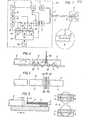
- FIGS. 1 and 2 The method of operation of the measuring arrangement according to the invention is shown in FIGS. 1 and 2.
- a light-emitting diode 1 feeds light into the optical fiber 2 via the optical fiber branch, which connects the sensor 6 to the electronic part 19 of the measuring arrangement.
- the emitted light of the LED 1 has a pulse shape, which is achieved by a feeding pulse generator 4 and a downstream pulse shaper 5.
- the sensor 6 contains luminescent material with at least two optical time constants ⁇ 1 and ⁇ 2 . In the exemplary embodiment shown, these materials with the relevant time constants are contained in spatially separated bodies 7, 8.
- the material body 7 with the time constant is firmly connected to the fiber end, while the material body 8 is arranged to be movable with the time constant ⁇ 2 , its position, which is determined by the measured variable, to be measured.
- This measured variable can be, for example, the position of another body, a force, an acceleration, a hydrostatic pressure, a liquid level or a flow. Due to changes in position between the bodies 7 and 8, the excitation light coming into the body 8 and coming from the light-emitting diode 1 varies, which in turn causes the intensity of the luminescence to vary with the time constant ⁇ 2 .
- the photodetector 9 for example a photodiode
- the detector amplifier 10 the light (optical signal) radiated by the sensor into the fiber 2 is converted into an electrical voltage.
- the amplifier 10 can be blocked during the duration of the excitation pulse by a control signal from the pulse shaper 5 in order to prevent light from the light-emitting diode 1, which reaches the photodetector 9 as a result of reflections, from falsifying the measurement signal.
- this can be reflected Light can be intercepted by an optical filter in front of the detector 9.
- Optical bandpass interference filters for the wavelength of the luminescent light of the Nd ions (1.06ju) are commercially available.
- the output signal of the detector amplifier 10 is divided in time into several S&H elements (sample and hold elements) 11, 12, 13, which are controlled synchronously by the pulse generator 4 via the delay elements 14, 15, 16.
- the time-divided signal is fed to a calculation element 17, which emits a signal which represents the measured variable, which is displayed in the display element 18.
- An S&H element is one that stores the value that was once present at its input and outputs it as an output variable. When a new control pulse arrives, the previously stored value is replaced by the new value present at the input.
- Figure 2 shows the temporal course of signals that occur in the measuring arrangement.
- the output signal 20 of the pulse generator 4 controls the timing.
- the output signal of the pulse shaper 5 can either consist of a pulse train of pulses of a fixed length T e or can be controlled by the calculation element 17 in such a way that an optimal excitation results.
- Curves 22 and 23 show the course of the luminescent light that decays with the time constants ⁇ 1 and ⁇ 2 .
- the pulses 24, 25, 26 show three time windows for inputting signals into the S&H elements 11, 12, 13.
- the calculation element 17 In the case described with two simple, clearly different time constants ⁇ 1 and ⁇ 2 , the calculation element is thus relatively simple and can even be expanded from analog circuits. In more complicated cases, in which one has to take into account a multi-exponential curve according to equation (2), several measuring points must be added to the time diagram (pulse 25 at time d i ). In this more general case, the calculation element 17 must solve a system of equations with a larger number of unknowns, which is determined by the number of superimposed exponential curves, which of course also determines the number of required measuring points in the time diagram. If the number of measuring points in the decay course exceeds the number of time constants, the system of equations is over-determined. This can be used to supply other information. If, for example, the time constant is temperature-dependent, the calculation of its value can result in a simultaneous temperature measurement.
- FIG. 2b shows a time diagram for a sensor structure, in which the luminescent light I 2 (curve 28) of the stationary body 8 decays with the time constant ⁇ 2 , which is considerably shorter than ⁇ 1 , while the luminescent light I, (curve 29) of the body 7 , which decays with the time constant ⁇ 1 , is much weaker than I 2 .
- An alternative embodiment of the detector system consists in that the analysis is carried out in the frequency level, for example with an analog arrangement as described in DE-OS 32 15 959.5.
- FIG. 3 shows an embodiment of a position sensor in which the luminescent materials 7 and 8 are arranged along the direction of propagation (the main direction of the fiber) of the light.
- the material 8 with the optical time constant ⁇ 2 is designed like a waveguide with totally reflecting intermediate surfaces 43.
- the absorption of incident light by the material 8 is selected such that the material 7 is also excited with the time constant ⁇ 1 .
- the excitation light and the luminescent light from the material 7 are modulated with the aid of a movable screen 36, the movement of which is a measure of the measured variable.
- the material 7 can preferably also be designed as a waveguide with totally reflecting intermediate surfaces 37.
- the screen 36 can also be made of a selectively absorbent material or a suitably arranged mirror.
- Figure 4 shows a sensor for magnetic field measurement, which does not need any moving parts.
- the sensor contains two polarizing plates 38, 39, the polarization planes of which are rotated 90 ° relative to one another.
- a material 40 In between is a material 40, the polarization-rotating properties of which depend on the size of the magnetic field to be measured.
- the material can be an area material, such as yttrium iron garnet.
- the material 40 can be replaced by electro-optically or elasto-optically sensitive material. Since the magneto-optical, electro-optical or elasto-optical properties of these materials are often temperature-dependent, you sometimes want to be able to measure the temperature of the encoder. This can be done in a simple manner by choosing a luminescent material with a temperature-dependent time constant and measuring it.
- FIG. 5 shows a position sensor in which the luminescent materials 7 and 8 are firmly joined together, for example melted, to form a simple bar structure, and are arranged in the manner of a bar clamped on one side. This is elastically deformed (bent) perpendicular to the longitudinal direction of the fiber 2 by applying a force 41.
- the luminescent light of the two materials 7 and 8, to which the optical time constants ⁇ 1 and ⁇ 2 belong is modulated as a function of the deflection of the bar mentioned. This is illustrated in the two sectional representations AA in FIG . 5 .
- the proportion of the area covered by the fiber 2 becomes larger for the material 7 and smaller for the material 8. This results in a change in the intensity quotient from the two luminescent light components.
Landscapes
- Physics & Mathematics (AREA)
- General Physics & Mathematics (AREA)
- Investigating, Analyzing Materials By Fluorescence Or Luminescence (AREA)
- Length Measuring Devices By Optical Means (AREA)
- Optical Transform (AREA)
- Photometry And Measurement Of Optical Pulse Characteristics (AREA)
- Light Guides In General And Applications Therefor (AREA)
Applications Claiming Priority (2)
| Application Number | Priority Date | Filing Date | Title |
|---|---|---|---|
| SE8202093A SE435967B (sv) | 1982-04-01 | 1982-04-01 | Fiberoptiskt luminiscensmetdon |
| SE8202093 | 1982-04-01 |
Publications (2)
| Publication Number | Publication Date |
|---|---|
| EP0091394A1 true EP0091394A1 (fr) | 1983-10-12 |
| EP0091394B1 EP0091394B1 (fr) | 1986-08-27 |
Family
ID=20346441
Family Applications (1)
| Application Number | Title | Priority Date | Filing Date |
|---|---|---|---|
| EP83710012A Expired EP0091394B1 (fr) | 1982-04-01 | 1983-03-22 | Dispositif à fibre optique pour mesurer des quantités physiques |
Country Status (6)
| Country | Link |
|---|---|
| US (1) | US4562348A (fr) |
| EP (1) | EP0091394B1 (fr) |
| JP (1) | JPS58182511A (fr) |
| CA (1) | CA1199197A (fr) |
| DE (1) | DE3365552D1 (fr) |
| SE (1) | SE435967B (fr) |
Cited By (4)
| Publication number | Priority date | Publication date | Assignee | Title |
|---|---|---|---|---|
| EP0115025A2 (fr) * | 1982-12-23 | 1984-08-08 | Wolfgang Dr. Ruhrmann | Capteur optique |
| EP0154025A1 (fr) * | 1983-12-29 | 1985-09-11 | INTERATOM Gesellschaft mit beschränkter Haftung | Procédé de la transformation directe des grandeurs mesurées en changements d'un signal lumineux guidé dans les deux sens dans un guide de lumière et palpeur hybride pour l'application de ce procédé |
| EP0238856A1 (fr) * | 1986-02-21 | 1987-09-30 | Degussa Aktiengesellschaft | Procédé et dispositif pour mesurer la période de diminution de fluorescence d'une substance fluorescente |
| WO1989002063A1 (fr) * | 1987-09-01 | 1989-03-09 | Plessey Overseas Limited | Ameliorations relatives aux detecteurs a fibre optique |
Families Citing this family (19)
| Publication number | Priority date | Publication date | Assignee | Title |
|---|---|---|---|---|
| SE418904B (sv) * | 1979-12-28 | 1981-06-29 | Asea Ab | Fiberoptiskt metdon for metning av fysikaliska storheter sasom lege, hastighet, acceleration, kraft, tryck, tojning och temperatur |
| SE435760B (sv) * | 1982-04-21 | 1984-10-15 | Asea Ab | Fiberoptisk legesgivare |
| US5090818A (en) * | 1982-08-06 | 1992-02-25 | Kleinerman Marcos Y | Fiber optic systems for sensing temperature and other physical variables |
| US5222810A (en) * | 1982-08-06 | 1993-06-29 | Kleinerman Marcos Y | Fiber optic systems for sensing temperature and other physical variables |
| US5004913A (en) * | 1982-08-06 | 1991-04-02 | Marcos Kleinerman | Remote measurement of physical variables with fiber optic systems - methods, materials and devices |
| GB8311256D0 (en) * | 1983-04-26 | 1983-06-02 | Central Electr Generat Board | Measuring external parameter |
| GB2156513B (en) * | 1984-03-28 | 1988-05-25 | Plessey Co Plc | Temperature measuring arrangements |
| FR2588380B1 (fr) * | 1985-10-07 | 1988-05-27 | Commissariat Energie Atomique | Dispositif d'examen a distance de defauts debouchant a la surface interne d'une cavite profonde |
| US4883354A (en) * | 1985-10-25 | 1989-11-28 | Luxtron Corporation | Fiberoptic sensing of temperature and/or other physical parameters |
| US4752141A (en) * | 1985-10-25 | 1988-06-21 | Luxtron Corporation | Fiberoptic sensing of temperature and/or other physical parameters |
| GB8531430D0 (en) * | 1985-12-20 | 1986-02-05 | Rosemount Eng Co Ltd | Displacement sensing apparatus |
| EP0288514A4 (fr) * | 1986-10-03 | 1990-01-08 | Conax Buffalo Corp | Appareil de protection a fibre optique. |
| US4785824A (en) * | 1987-06-22 | 1988-11-22 | Luxtron Corporation | Optical fiber probe for measuring the temperature of an ultrasonically heated object |
| GB8900304D0 (en) * | 1989-01-06 | 1989-03-08 | Lucas Ind Plc | Signal extraction apparatus |
| US5107445A (en) * | 1990-12-04 | 1992-04-21 | Luxtron Corporation | Modular luminescence-based measuring system using fast digital signal processing |
| CA2372637A1 (fr) * | 2002-02-20 | 2003-08-20 | Institut National D'optique | Capteurs optiques integres au cote de fibres optiques |
| US8201996B1 (en) | 2008-04-25 | 2012-06-19 | Ipitek, Inc. | Passive wavelength-division multiplexing (WDM) fiber-optic temperature sensor |
| US8206030B1 (en) * | 2008-05-19 | 2012-06-26 | Ipitek, Inc. | Multiple sensing tip optical fiber thermometer |
| WO2014172440A1 (fr) * | 2013-04-16 | 2014-10-23 | Watlow Electric Manufacturing Company | Dispositif de commande de processus à détection optique intégrée |
Citations (6)
| Publication number | Priority date | Publication date | Assignee | Title |
|---|---|---|---|---|
| DE2755713A1 (de) * | 1976-12-16 | 1978-06-22 | Alves Ronald Vieira | Optisches temperaturmessverfahren unter verwendung von phosphoreszierenden stoffen |
| GB2034460A (en) * | 1978-09-15 | 1980-06-04 | Asea Ab | Optical measuring device |
| US4223226A (en) * | 1978-07-26 | 1980-09-16 | Rockwell International Corporation | Fiber optic temperature sensor |
| DE3036682A1 (de) * | 1979-10-10 | 1981-04-23 | ASEA AB, Västerås | Faseroptisches temperaturmessgeraet |
| DE3101047A1 (de) * | 1980-01-24 | 1982-01-14 | ASEA AB, 72183 Västerås | "faseroptisches messgeraet zur messung einer kraft oder eines druckes" |
| DE3122788A1 (de) * | 1980-06-16 | 1982-02-11 | ASEA AB, 72183 Västerås | "faseroptische temperaturmessanordnung" |
Family Cites Families (2)
| Publication number | Priority date | Publication date | Assignee | Title |
|---|---|---|---|---|
| SE411955B (sv) * | 1978-06-02 | 1980-02-11 | Asea Ab | Fiberoptiskt metdon med hogst tva fibrer |
| US4356396A (en) * | 1980-12-17 | 1982-10-26 | Siemens Corporation | Fiber optical measuring device with compensating properties |
-
1982
- 1982-04-01 SE SE8202093A patent/SE435967B/sv not_active IP Right Cessation
-
1983
- 1983-03-22 EP EP83710012A patent/EP0091394B1/fr not_active Expired
- 1983-03-22 DE DE8383710012T patent/DE3365552D1/de not_active Expired
- 1983-03-30 JP JP58054986A patent/JPS58182511A/ja active Pending
- 1983-03-31 US US06/480,671 patent/US4562348A/en not_active Expired - Fee Related
- 1983-03-31 CA CA000425040A patent/CA1199197A/fr not_active Expired
Patent Citations (6)
| Publication number | Priority date | Publication date | Assignee | Title |
|---|---|---|---|---|
| DE2755713A1 (de) * | 1976-12-16 | 1978-06-22 | Alves Ronald Vieira | Optisches temperaturmessverfahren unter verwendung von phosphoreszierenden stoffen |
| US4223226A (en) * | 1978-07-26 | 1980-09-16 | Rockwell International Corporation | Fiber optic temperature sensor |
| GB2034460A (en) * | 1978-09-15 | 1980-06-04 | Asea Ab | Optical measuring device |
| DE3036682A1 (de) * | 1979-10-10 | 1981-04-23 | ASEA AB, Västerås | Faseroptisches temperaturmessgeraet |
| DE3101047A1 (de) * | 1980-01-24 | 1982-01-14 | ASEA AB, 72183 Västerås | "faseroptisches messgeraet zur messung einer kraft oder eines druckes" |
| DE3122788A1 (de) * | 1980-06-16 | 1982-02-11 | ASEA AB, 72183 Västerås | "faseroptische temperaturmessanordnung" |
Cited By (5)
| Publication number | Priority date | Publication date | Assignee | Title |
|---|---|---|---|---|
| EP0115025A2 (fr) * | 1982-12-23 | 1984-08-08 | Wolfgang Dr. Ruhrmann | Capteur optique |
| EP0115025A3 (en) * | 1982-12-23 | 1984-12-12 | Wolfgang Dr. Ruhrmann | Optical sensor |
| EP0154025A1 (fr) * | 1983-12-29 | 1985-09-11 | INTERATOM Gesellschaft mit beschränkter Haftung | Procédé de la transformation directe des grandeurs mesurées en changements d'un signal lumineux guidé dans les deux sens dans un guide de lumière et palpeur hybride pour l'application de ce procédé |
| EP0238856A1 (fr) * | 1986-02-21 | 1987-09-30 | Degussa Aktiengesellschaft | Procédé et dispositif pour mesurer la période de diminution de fluorescence d'une substance fluorescente |
| WO1989002063A1 (fr) * | 1987-09-01 | 1989-03-09 | Plessey Overseas Limited | Ameliorations relatives aux detecteurs a fibre optique |
Also Published As
| Publication number | Publication date |
|---|---|
| US4562348A (en) | 1985-12-31 |
| DE3365552D1 (en) | 1986-10-02 |
| SE435967B (sv) | 1984-10-29 |
| SE8202093L (sv) | 1983-10-02 |
| EP0091394B1 (fr) | 1986-08-27 |
| CA1199197A (fr) | 1986-01-14 |
| JPS58182511A (ja) | 1983-10-25 |
Similar Documents
| Publication | Publication Date | Title |
|---|---|---|
| EP0091394B1 (fr) | Dispositif à fibre optique pour mesurer des quantités physiques | |
| DE3511185C2 (fr) | ||
| EP0008089B1 (fr) | Télémètre laser à impulsion muni d'un corrélateur optique | |
| EP0057447B1 (fr) | Appareil de mesure de distance selon le principe de la mesure de temps de propagation d'une impulsion de lumière | |
| DE3036682C2 (fr) | ||
| EP0095673B2 (fr) | Senseur à fibre optique pour mesurer des grandeurs physiques | |
| DE3219423A1 (de) | Entfernungsmessverfahren und vorrichtung zu seiner durchfuehrung | |
| DE102010003843A1 (de) | Entfernungsmessgerät mit homogenisierender Messauswertung | |
| EP0238856B1 (fr) | Procédé et dispositif pour mesurer la période de diminution de fluorescence d'une substance fluorescente | |
| EP0151958A2 (fr) | Transducteur à fibres optiques pour mesurer des accélérations dynamiques | |
| DE4406865C2 (de) | Abstandsmeßvorrichtung | |
| EP0050306A2 (fr) | Dispositif de mesure à fibres optiques | |
| EP0095998A1 (fr) | Arrangement de mesure à fibres optiques | |
| DE1955403C3 (de) | Digitale Meßeinrichtung für Ströme in Hochspannungsleitern | |
| DE2451654B2 (de) | Vorrichtung zum Messen von Störstellen und/oder Längen von Glasfasern | |
| DE1253468B (de) | Vorrichtung zur Bestimmung der Entfernung zu einem Reflektor | |
| EP0096262A1 (fr) | Sensor à fibre optique pour mesurer des grandeurs dynamiques | |
| DE102012217655A1 (de) | Verfahren zum Bestimmen der relativen Zeitlage elektromagnetischer Pulse und Bestimmungsvorrichtung | |
| DE3530011C2 (fr) | ||
| EP0927357A1 (fr) | Detecteur pour mesurer l'intensite et/ou la tension d'un courant | |
| EP0244883B1 (fr) | Procédé de saisissage de données par ligne de transmission utilisant des capteurs optiques | |
| DE2754420A1 (de) | Ballistische messanordnung | |
| DE3511376A1 (de) | Verfahren und vorrichtung zur messung der beleuchtungsstaerke von einfallendem licht | |
| DE3732217B4 (de) | Verwendung einer fluoreszierenden Substanz | |
| CH678765A5 (fr) |
Legal Events
| Date | Code | Title | Description |
|---|---|---|---|
| PUAI | Public reference made under article 153(3) epc to a published international application that has entered the european phase |
Free format text: ORIGINAL CODE: 0009012 |
|
| AK | Designated contracting states |
Designated state(s): CH DE FR GB LI |
|
| 17P | Request for examination filed |
Effective date: 19840324 |
|
| GRAA | (expected) grant |
Free format text: ORIGINAL CODE: 0009210 |
|
| AK | Designated contracting states |
Kind code of ref document: B1 Designated state(s): CH DE FR GB LI |
|
| REF | Corresponds to: |
Ref document number: 3365552 Country of ref document: DE Date of ref document: 19861002 |
|
| ET | Fr: translation filed | ||
| PLBE | No opposition filed within time limit |
Free format text: ORIGINAL CODE: 0009261 |
|
| STAA | Information on the status of an ep patent application or granted ep patent |
Free format text: STATUS: NO OPPOSITION FILED WITHIN TIME LIMIT |
|
| 26N | No opposition filed | ||
| PGFP | Annual fee paid to national office [announced via postgrant information from national office to epo] |
Ref country code: FR Payment date: 19911223 Year of fee payment: 10 |
|
| PGFP | Annual fee paid to national office [announced via postgrant information from national office to epo] |
Ref country code: GB Payment date: 19920312 Year of fee payment: 10 |
|
| PGFP | Annual fee paid to national office [announced via postgrant information from national office to epo] |
Ref country code: CH Payment date: 19920326 Year of fee payment: 10 |
|
| PGFP | Annual fee paid to national office [announced via postgrant information from national office to epo] |
Ref country code: DE Payment date: 19920430 Year of fee payment: 10 |
|
| PG25 | Lapsed in a contracting state [announced via postgrant information from national office to epo] |
Ref country code: GB Effective date: 19930322 |
|
| PG25 | Lapsed in a contracting state [announced via postgrant information from national office to epo] |
Ref country code: LI Effective date: 19930331 Ref country code: CH Effective date: 19930331 |
|
| GBPC | Gb: european patent ceased through non-payment of renewal fee |
Effective date: 19930322 |
|
| PG25 | Lapsed in a contracting state [announced via postgrant information from national office to epo] |
Ref country code: FR Effective date: 19931130 |
|
| REG | Reference to a national code |
Ref country code: CH Ref legal event code: PL |
|
| PG25 | Lapsed in a contracting state [announced via postgrant information from national office to epo] |
Ref country code: DE Effective date: 19931201 |
|
| REG | Reference to a national code |
Ref country code: FR Ref legal event code: ST |