EP0090774A2 - Device for protecting an electrical apparatus against disturbances - Google Patents
Device for protecting an electrical apparatus against disturbances Download PDFInfo
- Publication number
- EP0090774A2 EP0090774A2 EP83810119A EP83810119A EP0090774A2 EP 0090774 A2 EP0090774 A2 EP 0090774A2 EP 83810119 A EP83810119 A EP 83810119A EP 83810119 A EP83810119 A EP 83810119A EP 0090774 A2 EP0090774 A2 EP 0090774A2
- Authority
- EP
- European Patent Office
- Prior art keywords
- cable
- plug
- conductors
- mhz
- interference
- Prior art date
- Legal status (The legal status is an assumption and is not a legal conclusion. Google has not performed a legal analysis and makes no representation as to the accuracy of the status listed.)
- Granted
Links
Images
Classifications
-
- H—ELECTRICITY
- H01—ELECTRIC ELEMENTS
- H01R—ELECTRICALLY-CONDUCTIVE CONNECTIONS; STRUCTURAL ASSOCIATIONS OF A PLURALITY OF MUTUALLY-INSULATED ELECTRICAL CONNECTING ELEMENTS; COUPLING DEVICES; CURRENT COLLECTORS
- H01R13/00—Details of coupling devices of the kinds covered by groups H01R12/70 or H01R24/00 - H01R33/00
- H01R13/66—Structural association with built-in electrical component
- H01R13/719—Structural association with built-in electrical component specially adapted for high frequency, e.g. with filters
Definitions
- the invention relates to an interference protection device according to the preamble of patent claim 1.
- interference filters are known to be composed of inductors and capacitors in a filter circuit arrangement which is dependent on the frequency range of the high-frequency interference to be suppressed or at least attenuated.
- the disadvantage here is that the high-frequency interference is only attenuated in the device itself, which requires a careful construction of the interference protection filter with regard to high-frequency radiation, which also takes up space in the device itself, and that an original Lich not equipped with a built-in interference filter if later need to attenuate high-frequency interference supplied via the power supply can only be protected with considerable effort or in an inadmissible manner, e.g. by means of attached or otherwise upstream, external and separate interference filters.
- the object of the invention is to provide a noise protection device of the type mentioned, with which high-frequency interference can be damped for any electrical device without great effort and without additional space requirement in front of the power terminals of the device.
- the interference protection device has the features stated in the characterizing part of patent claim 1.
- the present interference protection device can be easily and above all without great additional costs and without additional space requirements instead of the usual device Connection cable are used to keep high-frequency interference away from a device that is not equipped with a noise filter or to increase the effectiveness of a noise filter installed in the device.
- a particularly advantageous embodiment of the interference protection device consists in that the inductors provided for damping a lower frequency range, for example up to 1 MHz, are built into the power plug, and that the capacitors provided for damping a medium frequency range, for example 1 to 30 MHz, are installed in the power plug and in the device coupling are installed, and that the capacitances provided for damping a high frequency range, for example 30 MHz to 1 GHz, are given by the distributed capacitance formed from the conductors and a shielding of the cable.
- the inductances and capacitances required to achieve high-frequency interference attenuation over a very wide frequency band are distributed so favorably over the components of the connecting line that the connecting line, including the power plug and device coupling, has hardly larger dimensions than a conventional plug-in power connection line for an electrical device .
- the device coupling can have contact sockets for plugging onto contact pins of the device.
- the device coupling can have a housing that can be installed in a wall of the device, for example screwed or snapped, to which the cable is mechanically connected in a tensile manner and which contains at least one interference protection element connected to the conductors of the cable.
- plug elements can be arranged in this housing of the device coupling, which are firmly connected to the conductors of the cable and onto which a filter block containing at least one interference protection element is attached, which in turn is provided with terminals, for example plug terminals, for connecting conductors of the device .
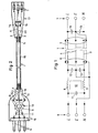
- the pluggable connection line for an electrical device shown schematically in FIG. 1 has a cable 1 with three wires 2, 3 and 4, in particular strands, and an outer metallic shield 5, furthermore at one end of the cable 1 three contact pins 6 for the phase conductor L, the neutral conductor N and the earth conductor E of an alternating current supply network, and at the other end of the cable 1 three corresponding contact sockets 7 with the same conductor designations for the device to be connected.
- the contact pin 6 for the earth conductor E is connected via the cable wire 4 to the contact socket 7 for the earth conductor E, the shield 5 of the cable 1 on both cables ends are also connected to the cable core 4.
- a winding 8 or 9 of a total of 10 current-compensated coil is connected to the contact pin 6 for the phase conductor L and to the contact pin 6 for the neutral conductor N.
- the other ends of the windings 8, 9 are connected to the cable core 2 or 3 and thus to the contact sockets 7 for the phase conductor connection and the neutral conductor connection of the device.
- the pin-side ends of the windings 8, 9 are also connected to one another via a first capacitor 11, while each cable-side end of the windings 8, 9 is connected to the earth wire 4 of the cable 1 via a second capacitor 12 or a third capacitor 13.
- the contact sockets 7 for the phase conductor L and the neutral conductor N are each connected via a fourth capacitor 14 and a fifth capacitor 15 to the contact socket 7 for the earth conductor E.
- the mentioned interference protection elements provided at the contact end of the cable 1 in a power plug 16 of the cable and the interference protection elements provided at the end of the cable 1 on the contact socket are in one device coupling 17 housed the cable.
- the power plug 16 has the three contact pins 6 in a known manner
- the device coupling 17 has the three contact sockets 7, the power plug 16 and the device coupling 17 being sprayed onto an insulating protective jacket 18 of the cable 1 or being connected to the cable 1 so as to be disconnectable.
- the cable 1 contains the insulated wires 2, 3 and 4 emerging from its two ends for the phase conductor, the neutral conductor and the earth conductor.
- the cores 2, 3, 4 are surrounded by the shield 5, for example a metal braid, which is provided at each end with a connecting strand 19 or 20 and is in turn encased by the protective insulating jacket 18.
- the earth wire 4 and the connecting strands 19, 12 of the shield 5 of the cable 1 are connected in the power plug 16 to the middle contact pin 6 intended for the earth wire E and in the device coupling 17 to the corresponding middle contact socket 7.
- the capacitor 11, the coil 10 and the capacitors 12 and 13 are installed in the mains plug 16, while the capacitors 14 and 15 are installed in the device coupling 17.
- the coil 10 is shown as a ring coil with a ferrite core and two symmetrical windings 8, 9. The components mentioned are connected to the contact pins 6, the contact sockets 7 and the cable cores 2, 3, 4 according to the diagram of FIG. 1.
- the above-mentioned components and their connections are overmoulded with a plastic material in the same injection molding process during the assembly of the entire connecting line shown in FIG. 2, so that they are protected against damage and impacts.
- the power plug 16 and the device coupling 17 can essentially have the outer dimensions of conventional power plugs and device couplings in the case of prefabricated cables (so-called cord sets). This also applies to the shielded cable 1, since its shield 5 increases its diameter only slightly.
- the present interference protection device thus corresponds to a conventional device connection line both in terms of its external shape and in terms of its use for connecting an electrical device to the power supply network, but causes a substantial attenuation of high-frequency interference on the power supply network.
- connection line For damping high-frequency interference in the medium and high frequency range above, for example, 1 MHz divided capacity of the shielded cable 1 is used, then compared to Fig. 2 results in a simplified connection line.
- the power plug 16 then only contains the coil 10, the windings 8, 9 of which are connected on the one hand to two contact pins 6 and on the other hand to the cable wires 2 and 3.
- the device coupling 7 is then of a conventional type. In this case, however, the connecting line can also be designed without a device coupling, ie it can be permanently connected to the device.
- the interference protection device can also have a device coupling that can be installed in a wall of the device.
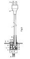
- a corresponding exemplary embodiment is shown in FIG. 3 and is described below.
- the exemplary embodiment of FIG. 3 has a cable 1 which is composed of three insulated conductor wires, a metallic shield and an insulating protective jacket (not shown).
- a power plug 16 with three contact pins 6 (only two visible) is connected to one end of the cable 1.
- Inductive and capacitive interference protection elements, such as are shown for example in FIG. 2, are accommodated in the mains plug 16.
- the power plug 16 can be a molded plastic part, in which the contact pins, the end of the cable 1 and the mentioned interference protection elements are integrated.
- the other end of the cable 1 is provided with a device coupling 21 which can be inserted into an opening in a device wall 22.
- the device coupling 21 has an outer housing 23 with an outer projection or flange 24, which is intended to rest against the device wall 22.
- the flange can have bores for screw fastening, or the housing 23 can be provided with holding elements which snap into the opening of the device wall 22 behind the latter when the housing 23 is inserted.
- the cable 1 guided into the interior of the housing 23 is provided with a flexible kink protection 25 clamped in the housing and with a strain relief clamp 26 also anchored in the housing.
- the individual conductor wires 27 of the cable 1 and its shielding are guided to a printed circuit board 28 accommodated in the housing 23 and are electrically connected there with electrically separated connection points, e.g. soldered.
- the printed circuit board 28 is also provided with a plurality of plug elements 29, of which only two are visible in FIG. 3 and which are in electrical connection with the wires 27 of the cable 1 in a manner not shown via conductor runs of the printed circuit board 28.
- a filter block 31 is plugged over the plug elements 29 corresponding to the printed circuit board 28 and contains, for example, further interference protection elements (not shown) integrated in the mass of the block, as shown in the device coupling 17 in FIG. 2.
- the filter block 31 On its rear end face, the filter block 31 is provided with three contact pins or contact tabs 32 in the present exemplary embodiment, which correspond to the contact sockets 7 of the device coupling of FIG. 2.
- the contact pins or contact tabs 32 are used to attach corresponding contact elements which are attached in a manner known per se to inner connecting wires or strands of the device.
- the housing 23 can contain further protective or switching elements, namely, for example, a tubular fuse 34 inserted into a holder 33.
- a tubular fuse 34 inserted into a holder 33.
- the holder is accommodated in a drawer-like compartment 35, which from the outside of the Housing 23 forth, ie on the outside of the device, can be pulled out.
- the electrical connection of the holder 33 takes place via flexible conductor wires which are connected to corresponding points on the printed circuit board 28.
- a switch (not shown) for switching the device on and off or a voltage selector can also be accommodated in the housing 23.
- the interference protection device shown in FIG. 3 with the power plug 16, the cable 1 and the device coupling 21 can be produced as a unit, with a likewise prefabricated filter block 31, which meets the requirements for the respective case, in order to meet specific interference protection requirements Contains interference protection elements, is plugged into the rear of the housing 23.
- the inner connecting wires of the device are first pulled outward through the opening of the device wall 22 and plugged onto the contact pins or tabs 32 of the filter block 31. Then the housing 23 of the device coupling 21 is inserted into the aforementioned opening, after which finally the housing 23 is firmly connected to the housing wall 22 in the manner described.
- the interference protection device can comprise a connecting line with a different filter circuit than the one described with reference to FIGS. 1 and 2.
Abstract
Description
Die Erfindung bezieht sich auf eine Störschutzeinrichtung gemäss dem Oberbegriff des Patentanspruchs 1.The invention relates to an interference protection device according to the preamble of patent claim 1.
Es ist üblich, elektrische Geräte, von welchen Hochfrequenzstörsignale, die vom Stromversorgungsnetz über die Anschlussleitung zum Gerät gelangen, fernzuhalten sind, an ihren Stromzuführungsklemmen mit Störschutzfiltern zu versehen. Das gilt auch, wenn durch Geräte erzeugte Hochfrequenzstörungen nicht ins Stromversorgungsnetz gelangen sollen. Solche Störschutzfilter setzen sich bekanntlich aus Induktivitäten und Kapazitäten in einer vom Frequenzbereich der zu unterdrückenden oder mindestens zu dämpfenden Hochfrequenzstörungen abhängigen Filter-Schaltungsanordnung zusammen. Nachteilig ist hierbei, dass die Dämpfung der Hochfrequenzstörungen erst im Gerät selbst erfolgt, was einen bezüglich Hochfrequenzstrahlung sorgfältigen Aufbau des Störschutzfilters erfordert, der zudem im Gerät selbst Raum beansprucht, und dass ein ursprünglich nicht mit einem eingebauten Störschutzfilter versehenes Gerät bei späterer Notwendigkeit einer Dämpfung von über die Stromversorgung zugeführten Hochfrequenzstörungen nur unter erheblichem Aufwand oder in unzulässiger Weise, z.B. durch angebaute oder sonstwie vorgeschaltete, äussere und separate Störschutzfilter, schützbar ist.It is customary to provide electrical devices, from which high-frequency interference signals which reach the device from the power supply network via the connecting line, from their power supply terminals with interference filters. This also applies if high-frequency interference caused by devices should not reach the power supply network. Such interference filters are known to be composed of inductors and capacitors in a filter circuit arrangement which is dependent on the frequency range of the high-frequency interference to be suppressed or at least attenuated. The disadvantage here is that the high-frequency interference is only attenuated in the device itself, which requires a careful construction of the interference protection filter with regard to high-frequency radiation, which also takes up space in the device itself, and that an original Lich not equipped with a built-in interference filter if later need to attenuate high-frequency interference supplied via the power supply can only be protected with considerable effort or in an inadmissible manner, e.g. by means of attached or otherwise upstream, external and separate interference filters.
Aufgabe der Erfindung ist, eine Störschutzeinrichtung der eingangs genannten Art zu schaffen, mit welcher Hochfrequenzstörungen für ein beliebiges elektrisches Gerät ohne grossen Aufwand und ohne zusätzlichen Raumbedarf vor den Stromanschlussklemmen des Geräts gedämpft werden können.The object of the invention is to provide a noise protection device of the type mentioned, with which high-frequency interference can be damped for any electrical device without great effort and without additional space requirement in front of the power terminals of the device.
Erfindungsgemäss weist zur Lösung dieser Aufgabe die Störschutzeinrichtung die im kennzeichnenden Teil des Patentanspruchs 1 angeführten Merkmale auf.According to the invention, to achieve this object, the interference protection device has the features stated in the characterizing part of patent claim 1.
Dadurch, dass die das Störschutzfilter bildenden induktiven und kapazitiven Störschutzelemente mindestens im Netzstecker und im Kabel (vorzugsweise als durch eine äussere Abschirmung des Kabels und die Leiter des Kabels gebildete verteilte Kapazität) eingebaut sind, kann die vorliegende Störschutzeinrichtung ohne weiteres und vor allem ohne grosse Mehrkosten sowie ohne zusätzlichen Raumbedarf statt der üblichen Geräte-Anschlussleitung benutzt werden, um Hochfrequenzstörungen von einem an sich mit keinem Störschutzfilter versehenen Gerät fernzuhalten oder gegebenenfalls die Wirkung eines im Gerät eingebauten Störschutzfilters zu erhöhen.Due to the fact that the inductive and capacitive interference protection elements forming the interference protection filter are installed at least in the mains plug and in the cable (preferably as a distributed capacitance formed by an external shielding of the cable and the conductors of the cable), the present interference protection device can be easily and above all without great additional costs and without additional space requirements instead of the usual device Connection cable are used to keep high-frequency interference away from a device that is not equipped with a noise filter or to increase the effectiveness of a noise filter installed in the device.
Eine besonders vorteilhafte Ausführungsform der erfindungsgemässen Störschutzeinrichtung besteht darin, dass die zur Dämpfung eines unteren Frequenzbereichs, beispielsweise bis 1 MHz, vorgesehenen Induktivitäten im Netzstecker eingebaut sind, dass die zur Dämpfung eines mittleren Frequenzbereichs, beispielsweise 1 bis 30 MHz, vorgesehenen Kondensatoren im Netzstecker und in der Gerätekupplung eingebaut sind, und dass die zur Dämpfung eines hohen Frequenzbereichs, beispielsweise 30 MHz bis 1 GHz, vorgesehenen Kapazitäten durch die verteilte Kapazität, gebildet aus den Leitern und einer Abschirmung des Kabels gegeben sind. Bei dieser Ausführungsform sind die zur Erzielung einer Dämpfung von Hochfrequenzstörungen über ein sehr breites Frequenzband erforderlichen Induktivitäten und Kapazitäten derart günstig über die Bestandteile der Anschlussleitung verteilt, dass die Anschlussleitung einschliesslich Netzstecker und Gerätekupplung kaum grössere Abmessungen hat, als eine konventionelle steckbare Stromanschlussleitung für ein elektrisches Gerät.A particularly advantageous embodiment of the interference protection device according to the invention consists in that the inductors provided for damping a lower frequency range, for example up to 1 MHz, are built into the power plug, and that the capacitors provided for damping a medium frequency range, for example 1 to 30 MHz, are installed in the power plug and in the device coupling are installed, and that the capacitances provided for damping a high frequency range, for example 30 MHz to 1 GHz, are given by the distributed capacitance formed from the conductors and a shielding of the cable. In this embodiment, the inductances and capacitances required to achieve high-frequency interference attenuation over a very wide frequency band are distributed so favorably over the components of the connecting line that the connecting line, including the power plug and device coupling, has hardly larger dimensions than a conventional plug-in power connection line for an electrical device .
Die Gerätekupplung kann in bekannter Art Kontaktbuchsen zum Aufstecken auf Kontaktstifte des Gerätes aufweisen. Alternativ kann die Gerätekupplung ein in einer Wand des Gerätes einbaubares, zum Beispiel anschraubbares oder einrastbares Gehäuse aufweisen, mit welchem das Kabel zugfest mechanisch verbunden ist und welches mindestens ein an die Leiter des Kabels angeschlossenes Störschutzelement enthält. Insbesondere können in diesem Gehäuse der Gerätekupplung Steckerelemente angeordnet sein, welche mit den Leitern des Kabels elektrisch fest verbunden sind und auf welche ein mindestens ein Störschutzelement enthaltender Filterblock aufgesteckt ist, der seinerseits mit Klemmen, zum Beispiel Steckerklemmen, zum Anschliessen von Leitern des Gerätes versehen ist.In a known manner, the device coupling can have contact sockets for plugging onto contact pins of the device. Alternatively, the device coupling can have a housing that can be installed in a wall of the device, for example screwed or snapped, to which the cable is mechanically connected in a tensile manner and which contains at least one interference protection element connected to the conductors of the cable. In particular, plug elements can be arranged in this housing of the device coupling, which are firmly connected to the conductors of the cable and onto which a filter block containing at least one interference protection element is attached, which in turn is provided with terminals, for example plug terminals, for connecting conductors of the device .
Ausführungsbeispiele des Erfindungsgegenstandes werden nachstehend anhand der Zeichnungen erläutert. Es zeigen:
- Fig. 1 ein Schaltschema eines Ausführungsbeispiels der erfindungsgemässen Störschutzeinrichtung,
- Fig. 2 eine aufgeschnittene Ansicht einer ersten Bauform des genannten Ausführungsbeispiels mit einer steckbaren Gerätekupplung, und
- Fig. 3 eine teilweise aufgeschnittene Ansicht einer weiteren Bauform der erfindungsgemässen Störschutzeinrichtung mit einer im Gerät einbaubaren Gerätekupplung.
- 1 is a circuit diagram of an embodiment of the interference protection device according to the invention,
- Fig. 2 is a cutaway view of a first design of the above embodiment with a plug-in device connector, and
- 3 shows a partially cut-away view of a further design of the interference protection device according to the invention with a device coupling that can be installed in the device.
Die in Fig. 1 schematisch dargestellte steckbare Anschlussleitung für ein elektrisches Gerät weist ein Kabel 1 mit drei Adern 2, 3 und 4, insbesondere Litzen, und einer äusseren metallischen Abschirmung 5 auf, ferner am einen Ende des Kabels 1 drei Kontaktstifte 6 für den Phasenleiter L, den Nulleiter N und den Erdleiter E eines Wechselstrom-Versorgungsnetzes, sowie am andern Ende des Kabels 1 drei entsprechende Kontaktbuchsen 7 mit gleichen Leiterbezeichnungen für das anzuschliessende Gerät.The pluggable connection line for an electrical device shown schematically in FIG. 1 has a cable 1 with three
Der Kontaktstift 6 für den Erdleiter E ist über die Kabelader 4 mit der Kontaktbuchse 7 für den Erdleiter E verbunden, wobei die Abschirmung 5 des Kabels 1 an beiden Kabelenden ebenfalls mit der Kabelader 4 verbunden ist. An den Kontaktstift 6 für den Phasenleiter L sowie an den Kontaktstift 6 für den Nulleiter N ist je eine Wicklung 8 bzw. 9 einer gesamthaft mit 10 bezeichneten stromkompensierten Spule angeschlossen. Die anderen Enden der Wicklungen 8, 9 sind mit der Kabelader 2 bzw. 3 und damit mit den Kontaktbuchsen 7 für den Phasenleiteranschluss und den Nulleiteranschluss des Geräts verbunden.The
Die kontaktstiftseitigen Enden der Wicklungen 8, 9 sind zudem über einen ersten Kondensator 11 miteinander verbunden, während jedes kabelseitige Ende der Wicklungen 8, 9 über einen zweiten Kondensator 12 bzw. einen dritten Kondensator 13 mit der Erdleiterader 4 des Kabels 1 verbunden ist. Am andern Kabelende sind die Kontaktbuchsen 7 für den Phasenleiter L und den Nulleiter N über je einen vierten Kondensator 14 bzw. einen fünften Kondensator 15 mit der Kontaktbuchse 7 für den Erdleiter E verbunden.The pin-side ends of the
Die angeführten elektrischen Bauteile, nämlich die Spule 10 mit den symmetrischen Wicklungen 8 und 9, die Kondensatoren 11 bis 15 sowie die verteilte Kapazität der Abschirmung 5 des Kabels 1 gegenüber den Kabeladern 2 und 3 bilden eine Filterschaltung mit folgenden Dämpfungseigenschaften:
- In einem unteren Frequenzbereich, der sich beispielsweise bis 1 MHz erstreckt, wird die Dämpfung von über die
Kontaktstifte 6 eintreffenden Hochfrequenzstörungen im wesentlichen durch die Induktivitäten derWicklungen 8, 9 derSpule 10 bewirkt. Hochfrequenzstörungen in einem mittleren, sich beispielsweise von 1 bis 30 MHz erstreckenden Frequenzbereich werden im wesentlichen durch dieKondensatoren 11 bis 15 gedämpft, während zur Dämpfung von Hochfrequenzstörungen in einem hohen Frequenzbereich von beispielsweise 30 MHz bis 1 GHz vor allem die verteilte Kapazität zwischen denAdern Abschirmung 5 des Kabels 1 wirksam ist. Da die verteilte Kapazität der Abschirmung parallel zu dendiskreten Kondensatoren 12 bis 15 liegt, kann sie einen Teil der zur Erzielung der gewünschten Dämpfung erforderlichen Kapazitäten bilden, so dass dieKondensatoren 12 bis 15 entsprechend kleiner diemensioniert werden oder als diskrete Kondensatoren überhaupt wegfallen können.
- In a lower frequency range, which extends for example up to 1 MHz, the damping of high-frequency interference arriving via the
contact pins 6 is essentially caused by the inductances of thewindings 8, 9 of thecoil 10. High-frequency interference in a medium frequency range, for example extending from 1 to 30 MHz, is essentially attenuated by thecapacitors 11 to 15, while, in order to attenuate high-frequency interference in a high frequency range, for example 30 MHz to 1 GHz, the distributed capacitance between thewires 2 in particular , 3 and theshield 5 of the cable 1 is effective. Since the distributed capacitance of the shield lies parallel to thediscrete capacitors 12 to 15, it can form part of the capacitances required to achieve the desired attenuation, so that thecapacitors 12 to 15 are dimensioned correspondingly smaller or can even be omitted as discrete capacitors.
Bei der vorliegenden Störschutzeinrichtung sind gemäss Fig. 2 die erwähnten, am kontaktstiftseitigen Ende des Kabels 1 vorgesehenen Störschutzelemente in einem Netzstecker 16 des Kabels und die am kontaktbuchsenseitigen Ende des Kabels 1 vorgesehenen Störschutzelemente in einer Gerätekupplung 17 des Kabels untergebracht. Der Netzstecker 16 weist in bekannter Weise die drei Kontaktstifte 6 auf, die Gerätekupplung 17 die drei Kontaktbuchsen 7, wobei der Netzstecker 16 und die Gerätekupplung 17 auf einen Isolierschutzmantel 18 des Kabels 1 aufgespritzt oder mit dem Kabel 1 abklemmbar verbunden sind.In the case of the present interference protection device, according to FIG. 2, the mentioned interference protection elements provided at the contact end of the cable 1 in a
Das Kabel 1 enthält die aus seinen beiden Enden austretenden isolierten Adern 2, 3 und 4 für den Phasenleiter, den Nullleiter und den Erdleiter. Die Adern 2, 3, 4 sind von der beispielsweise als Metallgeflecht ausgebildeten Abschirmung 5 umgeben, die an ihren Enden mit je einer Anschlusslitze 19 bzw. 20 versehen ist und ihrerseits vom Isolierschutzmantel 18 umhüllt ist. Die Erdleiterader 4 und die Anschlusslitzen 19, 12 der Abschirmung 5 des Kabels 1 sind im Netzstecker 16 mit dem mittleren, für den Erdleiter E bestimmten Kontaktstift 6 und in der Gerätekupplung 17 mit der entsprechenden mittleren Kontaktbuchse 7 verbunden.The cable 1 contains the
Im Netzstecker 16 sind der Kondensator 11, die Spule 10 und die Kondensatoren 12 und 13 eingebaut, während in der Gerätekupplung 17 die Kondensatoren 14 und 15 eingebaut sind. Die Spule 10 ist als Ringspule mit einem Ferritkern und zwei symmetrischen Wicklungen 8, 9 darstellt. Die genannten Bauteile sind mit den Kontaktstiften 6, den Kontaktbuchsen 7 und den Kabeladern 2, 3, 4 gemäss dem Schema der Fig. 1 verbunden.The
Vorzugsweise werden die genannten Bauteile und ihre Verbindungen bei der Konfektionierung der gesamten, in Fig. 2 dargestellten Anschlussleitung im gleichen Spritzvorgang mit einem Kunststoffmaterial umspritzt, so dass sie vor Beschädigung und Stössen geschützt sind. Da die vorgesehene Spule 10 und die Kondensatoren 11 bis 15 verhältnismässig klein sind, können der Netzstecker 16 und die Gerätekupplung 17 im wesentlichen die äusseren Abmessungen konventioneller Netzstecker und Gerätekupplungen bei konfektionierten Kabeln (sog. Cord-Sets) haben. Dies gilt auch für das abgeschirmte Kabel 1, da dessen Abschirmung 5 seinen Durchmesser nur geringfügig vergrössert. Somit entspricht die vorliegende Störschutzeinrichtung sowohl bezüglich äusserer Form als auch bezüglich ihrer Anwendung zur Verbindung eines elektrischen Geräts mit dem Stromversorgungsnetz einer üblichen Geräteanschlussleitung, bewirkt jedoch eine wesentliche Dämpfung von Hochfrequenzströrungen auf dem Stromversorgungsnetz.Preferably, the above-mentioned components and their connections are overmoulded with a plastic material in the same injection molding process during the assembly of the entire connecting line shown in FIG. 2, so that they are protected against damage and impacts. Since the
Falls, wie bereits im Zusammenhang mit Fig. 1 erwähnt, zur Dämpfung von Hochfrequenzstörung im mittleren und hohen Frequenzbereich oberhalb beispielsweise 1 MHz einzig die verteilte Kapazität des abgeschirmten Kabels 1 benutzt wird, dann ergibt sich gegenüber Fig. 2 eine vereinfachte Anschlussleitung. Der Netzstecker 16 enthält dann bloss die Spule 10, deren Wicklungen 8, 9 einerseits mit zwei Kontaktstiften 6 und andererseits mit den Kabeladern 2 und 3 verbunden sind. Die Gerätekupplung 7 ist dann konventioneller Bauart. Die Anschlussleitung kann in diesem Fall aber auch ohne eine Gerätekupplung ausgebildet sein, d.h. fest an das Gerät angeschlossen sein.If, as already mentioned in connection with FIG. 1, only the ver. For damping high-frequency interference in the medium and high frequency range above, for example, 1 MHz divided capacity of the shielded cable 1 is used, then compared to Fig. 2 results in a simplified connection line. The
Statt einer steckbaren Gerätekupplung 17 kann die Störschutzeinrichtung auch eine in eine Wand des Gerätes einbaubare Gerätekupplung aufweisen. Ein entsprechendes Ausführungsbeispiel ist in Fig. 3 dargestellt und wird nachstehend beschrieben.Instead of a plug-in
In Uebereinstimmung mit Fig. 2 weist das Ausführungsbeispiel der Fig. 3 ein Kabel 1 auf, das sich aus drei isolierten Leiteradern, einer metallischen Abschirmung und einem Isolierschutzmantel (nicht dargestellt) zusammensetzt. An das eine Ende des Kabels 1 ist ein Netzstecker 16 mit drei Kontaktstiften 6 (nur zwei sichtbar) angeschlossen. Im Netzstecker 16 sind induktive und kapazitive Störschutzelemente untergebracht, wie sie beispielsweise in Fig. 2 dargestellt sind. Der Netzstecker 16 kann ein Kunststoff-Spritzteil sein, in welches die Kontaktstifte, das Ende des Kabels 1 und die erwähnten Störschutzelemente integriert sind.In accordance with FIG. 2, the exemplary embodiment of FIG. 3 has a cable 1 which is composed of three insulated conductor wires, a metallic shield and an insulating protective jacket (not shown). A
Das andere Ende des Kabels 1 ist mit einer Gerätekupplung 21 versehen, welche in eine Oeffnung einer Gerätewand 22 einsetzbar ist. Die Gerätekupplung 21 hat ein äusseres Gehäuse 23 mit einem äusseren Vorsprung oder Flansch 24, der zum Anliegen an der Gerätewand 22 bestimmt ist. Zur Befestigung der Gerätekupplung 21 an der Gerätewand 22 kann der Flansch Bohrungen für eine Schraubbefestigung aufweisen, oder das Gehäuse 23 kann mit Halteelementen versehen sein, welche beim Einsetzen des Gehäuses 23 in die Oeffnung der Gerätewand 22 hinter dieser einrasten.The other end of the cable 1 is provided with a
In an sich bekannter Weise ist das in das Innere des Gehäuses 23 geführte Kabel 1 mit einem im Gehäuse eingeklemmten, biegsamen Knickschutz 25 und mit einer ebenfalls im Gehäuse verankerten Zugentlastungsklemme 26 versehen. Die einzelnen Leiteradern 27 des Kabels 1 sowie dessen Abschirmung sind an eine im Gehäuse 23 untergebrachte Leiterplatte 28 geführt und dort mit elektrisch getrennten Anschlusspunkten elektrisch verbunden, z.B. verlötet.In a manner known per se, the cable 1 guided into the interior of the
Die Leiterplatte 28 ist zudem mit mehreren Steckerelementen 29 versehen, von welchen in Fig. 3 nur zwei sichtbar sind und welche in nicht dargestellter Weise über Leiterzüge der Leiterplatte 28 mit den Adern 27 des Kabels 1 in elektrischer Verbindung stehen. Ueber den Steckerelementen 29 der Leiterplatte 28 entsprechende Steckerelemente 30 ist ein Filterblock 31 aufgesteckt, der beispielsweise in der Masse des Blocks integrierte weitere Störschutzelemente (nicht dargestellt) enthält, wie sie in der Gerätekupplung 17 der Fig. 2 dargestellt sind. An seiner hinteren Stirnseite ist der Filterblock 31 mit im vorliegenden Ausführungsbeispiel drei Kontaktstiften oder Kontaktlaschen 32 versehen, welche den Kontaktbuchsen 7 der Gerätekupplung der Fig. 2 entsprechen. Die Kontaktstifte oder Kontaktlaschen 32 dienen dazu, entsprechende Kontaktorgane aufzustecken, welche in an sich bekannter Weise an inneren Anschlussdrähten oder -litzen des Gerätes angebracht sind.The printed
Wie in Fig. 3 dargestellt, kann das Gehäuse 23 weitere Schutz- oder Schaltelemente enthalten, nämlich beispielsweise eine in einen Halter 33 eingelegte röhrchenförmige Schmelzsicherung 34. Um gegebenenfalls die Schmelzsicherung 34 auswechseln zu können, ist der Halter in einem schubladenartigen Fach 35 untergebracht, das von der Aussenseite des Gehäuses 23 her, also an der Aussenseite des Gerätes, nach aussen gezogen werden kann. Der elektrische Anschluss des Halters 33 erfolgt über biegsame Leiterdrähte, welche an entsprechende Punkte der Leiterplatte 28 angeschlossen sind. Anstelle der dargestellten Schmelzsicherung 34 oder zusätzlich zu dieser kann im Gehäuse 23 auch ein von aussen betätigbarer Schalter (nicht dargestellt) für das Ein- und Ausschalten des Gerätes oder ein Spannungswähler untergebracht sein.As shown in FIG. 3, the
Wie leicht einzusehen ist, kann die in Fig. 3 dargestellte Störschutzeinrichtung mit dem Netzstecker 16, dem Kabel 1 und der Gerätekupplung 21 als eine Einheit hergestellt werden, wobei zur Erfüllung spezifischer Störschutzanforderungen jeweils ein ebenfalls vorfabrizierter Filterblock 31, der die für den jeweiligen Fall erforderlichen Störschutzelemente enthält, auf die Hinterseite des Gehäuses 23 gesteckt wird. Zum Anschliessen einer solchen mit dem Speisekabel eine Einheit bildenden Störschutzeinrichtung an das betreffende Gerät werden vorerst die inneren Anschlussdrähte des Gerätes durch die Oeffnung der Gerätewand 22 nach aussen gezogen und auf die Kontaktstifte oder -laschen 32 des Filterblocks 31 gesteckt. Hierauf wird das Gehäuse 23 der Gerätekupplung 21 in die genannte Oeffnung eingeführt, wonach abschliessend das Gehäuse 23 mit der Gehäusewand 22 in der beschriebenen Weise fest verbunden wird.As can be easily seen, the interference protection device shown in FIG. 3 with the
Es versteht sich, dass die erfindungsgemässe Störschutzeinrichtung eine Anschlussleitung mit anderer Filterschaltung als diejenige umfassen kann, die anhand der Fig. 1 und 2 beschrieben wurde.It goes without saying that the interference protection device according to the invention can comprise a connecting line with a different filter circuit than the one described with reference to FIGS. 1 and 2.
Claims (9)
Applications Claiming Priority (2)
| Application Number | Priority Date | Filing Date | Title |
|---|---|---|---|
| CH1887/82 | 1982-03-26 | ||
| CH188782 | 1982-03-26 |
Publications (3)
| Publication Number | Publication Date |
|---|---|
| EP0090774A2 true EP0090774A2 (en) | 1983-10-05 |
| EP0090774A3 EP0090774A3 (en) | 1986-11-20 |
| EP0090774B1 EP0090774B1 (en) | 1989-03-01 |
Family
ID=4220919
Family Applications (1)
| Application Number | Title | Priority Date | Filing Date |
|---|---|---|---|
| EP19830810119 Expired EP0090774B1 (en) | 1982-03-26 | 1983-03-23 | Device for protecting an electrical apparatus against disturbances |
Country Status (2)
| Country | Link |
|---|---|
| EP (1) | EP0090774B1 (en) |
| DE (1) | DE3379308D1 (en) |
Cited By (12)
| Publication number | Priority date | Publication date | Assignee | Title |
|---|---|---|---|---|
| DE3440573A1 (en) * | 1984-11-07 | 1986-05-07 | Vogt electronic AG, 8391 Erlau | ELECTRIC COMPENSATED THROTTLE IN A EUROSTECKER |
| EP0181286A1 (en) * | 1984-10-29 | 1986-05-14 | Ascom Autophon Ag | Shielded device for protecting telecommunication lines against disturbances |
| EP0502467A1 (en) * | 1991-03-07 | 1992-09-09 | Taller GmbH | Holding device for toroidal core throttle of a main plug |
| BE1005762A3 (en) * | 1992-04-14 | 1994-01-18 | Cable And Wire Assemblies Afge | Plug for UK countries with a dual cord not protected against fault signals |
| GB2271472A (en) * | 1992-05-15 | 1994-04-13 | Kainstar Limited | Filtered electrical plug. |
| GB2288493A (en) * | 1994-04-13 | 1995-10-18 | Cablerias Conductoras Sa | Electric plug |
| EP0910136A2 (en) * | 1997-08-19 | 1999-04-21 | Statpower Technologies Corporation | DC connection method |
| EP0918373A2 (en) * | 1997-09-01 | 1999-05-26 | Teknoalfa S.r.l. | Multipolar connection system for an electric apparatus which produces electromagnetic noise |
| WO2001097337A1 (en) * | 2000-06-16 | 2001-12-20 | Valtimo Components Oy | Connector |
| EP0988872B1 (en) * | 1998-09-21 | 2004-12-01 | Hess & Volk GmbH | Plug device for generating bio-positive waves |
| US6984148B1 (en) | 2004-07-16 | 2006-01-10 | Xantrex Technology Inc. | Electrical connector apparatus and cover therefor |
| ITUA20164562A1 (en) * | 2016-06-21 | 2017-12-21 | D E M S P A | Electric cable with filter |
Families Citing this family (2)
| Publication number | Priority date | Publication date | Assignee | Title |
|---|---|---|---|---|
| CA2703071C (en) * | 2007-10-24 | 2016-10-18 | Afl Telecommunications Llc | Ac mains filter and power supply system |
| CN111613938A (en) * | 2020-06-09 | 2020-09-01 | 深圳市睿臻信息技术服务有限公司 | Device and method for reducing background noise |
Citations (6)
| Publication number | Priority date | Publication date | Assignee | Title |
|---|---|---|---|---|
| GB447033A (en) * | 1934-08-08 | 1935-02-26 | Gerard De Monge | Improvements in interference eliminators for radio reception |
| GB714818A (en) * | 1952-10-10 | 1954-09-01 | Belling & Lee Ltd | Improvements in or relating to electrical multicontact connectors |
| US3191132A (en) * | 1961-12-04 | 1965-06-22 | Mayer Ferdy | Electric cable utilizing lossy material to absorb high frequency waves |
| US3488759A (en) * | 1966-05-02 | 1970-01-06 | Winegard Co | Coax connector unit |
| GB2069253A (en) * | 1980-02-08 | 1981-08-19 | Rca Corp | Ac power line assembly |
| DE3109766A1 (en) * | 1980-03-13 | 1982-01-28 | TDK Electronics Co., Ltd., Tokyo | Apparatus plug socket |
-
1983
- 1983-03-23 DE DE8383810119T patent/DE3379308D1/en not_active Expired
- 1983-03-23 EP EP19830810119 patent/EP0090774B1/en not_active Expired
Patent Citations (6)
| Publication number | Priority date | Publication date | Assignee | Title |
|---|---|---|---|---|
| GB447033A (en) * | 1934-08-08 | 1935-02-26 | Gerard De Monge | Improvements in interference eliminators for radio reception |
| GB714818A (en) * | 1952-10-10 | 1954-09-01 | Belling & Lee Ltd | Improvements in or relating to electrical multicontact connectors |
| US3191132A (en) * | 1961-12-04 | 1965-06-22 | Mayer Ferdy | Electric cable utilizing lossy material to absorb high frequency waves |
| US3488759A (en) * | 1966-05-02 | 1970-01-06 | Winegard Co | Coax connector unit |
| GB2069253A (en) * | 1980-02-08 | 1981-08-19 | Rca Corp | Ac power line assembly |
| DE3109766A1 (en) * | 1980-03-13 | 1982-01-28 | TDK Electronics Co., Ltd., Tokyo | Apparatus plug socket |
Cited By (17)
| Publication number | Priority date | Publication date | Assignee | Title |
|---|---|---|---|---|
| EP0181286A1 (en) * | 1984-10-29 | 1986-05-14 | Ascom Autophon Ag | Shielded device for protecting telecommunication lines against disturbances |
| DE3440573A1 (en) * | 1984-11-07 | 1986-05-07 | Vogt electronic AG, 8391 Erlau | ELECTRIC COMPENSATED THROTTLE IN A EUROSTECKER |
| EP0184009A2 (en) * | 1984-11-07 | 1986-06-11 | VOGT electronic Aktiengesellschaft | Mains plug suppressing interference caused by the supply current |
| EP0184009A3 (en) * | 1984-11-07 | 1988-09-21 | Vogt Electronic Aktiengesellschaft | Mains plug suppressing interference caused by the supply current |
| EP0502467A1 (en) * | 1991-03-07 | 1992-09-09 | Taller GmbH | Holding device for toroidal core throttle of a main plug |
| BE1005762A3 (en) * | 1992-04-14 | 1994-01-18 | Cable And Wire Assemblies Afge | Plug for UK countries with a dual cord not protected against fault signals |
| GB2271472A (en) * | 1992-05-15 | 1994-04-13 | Kainstar Limited | Filtered electrical plug. |
| GB2288493B (en) * | 1994-04-13 | 1997-12-24 | Cablerias Conductoras Sa | Electrical plug |
| GB2288493A (en) * | 1994-04-13 | 1995-10-18 | Cablerias Conductoras Sa | Electric plug |
| EP0910136A2 (en) * | 1997-08-19 | 1999-04-21 | Statpower Technologies Corporation | DC connection method |
| EP0910136A3 (en) * | 1997-08-19 | 2000-08-30 | Statpower Technologies Partnership | DC connection method |
| EP0918373A2 (en) * | 1997-09-01 | 1999-05-26 | Teknoalfa S.r.l. | Multipolar connection system for an electric apparatus which produces electromagnetic noise |
| EP0918373A3 (en) * | 1997-09-01 | 1999-11-17 | Teknoalfa S.r.l. | Multipolar connection system for an electric apparatus which produces electromagnetic noise |
| EP0988872B1 (en) * | 1998-09-21 | 2004-12-01 | Hess & Volk GmbH | Plug device for generating bio-positive waves |
| WO2001097337A1 (en) * | 2000-06-16 | 2001-12-20 | Valtimo Components Oy | Connector |
| US6984148B1 (en) | 2004-07-16 | 2006-01-10 | Xantrex Technology Inc. | Electrical connector apparatus and cover therefor |
| ITUA20164562A1 (en) * | 2016-06-21 | 2017-12-21 | D E M S P A | Electric cable with filter |
Also Published As
| Publication number | Publication date |
|---|---|
| EP0090774B1 (en) | 1989-03-01 |
| EP0090774A3 (en) | 1986-11-20 |
| DE3379308D1 (en) | 1989-04-06 |
Similar Documents
| Publication | Publication Date | Title |
|---|---|---|
| DE3109766C2 (en) | ||
| EP0090774B1 (en) | Device for protecting an electrical apparatus against disturbances | |
| DE2951528C2 (en) | ||
| DE2524582A1 (en) | CABLE CONNECTION ELEMENT FOR A CABLE WITH INNER AND OUTSIDE CONDUCTORS | |
| EP0267403A2 (en) | Capacitive separating circuit | |
| DE19704317A1 (en) | Electrical socket, in particular for a telephone connection | |
| DE2621132A1 (en) | REMOVAL DEVICE FOR EXPLOSION ENGINES | |
| DE4126401A1 (en) | FILTER ADAPTER FOR COAXIAL CONNECTORS PLACED IN A PLATE | |
| DE3233572C2 (en) | Single-phase termination plug-in connection for connecting a cable conductor to a switching device, in particular to an SF ↓ 6 ↓ switchgear | |
| DE69911437T2 (en) | EXTERNAL FILTER BOX | |
| DE60131324T2 (en) | Filtered electrical connector with ferrite core coil | |
| DE60008719T2 (en) | INPUT / OUTPUT CONNECTOR ASSEMBLY WITH GROUNDING ARRANGEMENT FOR SHIELDED CABLES AND METHOD FOR PRODUCING AND ASSEMBLING SUCH A CONNECTOR | |
| DE3148351C2 (en) | Suppressor plug | |
| DE3427361C1 (en) | Connection between a coaxial plug connector and a coaxial cable | |
| DE202018100223U1 (en) | High-voltage connector | |
| EP0568048B1 (en) | Data transmission cable | |
| DE2015445A1 (en) | Connector arrangement with surge arresters for coaxial cables and lines, especially for telecommunication purposes | |
| DE19845006C1 (en) | Overhead cable connector for MV electrical network cables has corresponding cable wire ends enclosed by common connector and field control body contained within outer insulator | |
| EP0184009B1 (en) | Mains plug suppressing interference caused by the supply current | |
| EP0174578B1 (en) | Appliance plug having an electrical-interference elimination filter connected thereto | |
| CH660261A5 (en) | EMP suppressor in a coaxial conductor | |
| DE4311125B4 (en) | EMC filters for systems, systems and shielded rooms | |
| DE4226463C2 (en) | Shielding device for an electrical cable | |
| DE3414811A1 (en) | DISCONNECTING DEVICE FOR CONNECTING TWO COAXIAL CABLES TERMINATED WITH COAXIAL CONNECTORS | |
| DE2339559C2 (en) | Capacitor arrangement |
Legal Events
| Date | Code | Title | Description |
|---|---|---|---|
| PUAI | Public reference made under article 153(3) epc to a published international application that has entered the european phase |
Free format text: ORIGINAL CODE: 0009012 |
|
| AK | Designated contracting states |
Kind code of ref document: A2 Designated state(s): CH DE FR GB LI NL Designated state(s): CH DE FR GB LI NL |
|
| PUAL | Search report despatched |
Free format text: ORIGINAL CODE: 0009013 |
|
| AK | Designated contracting states |
Kind code of ref document: A3 Designated state(s): CH DE FR GB LI NL |
|
| RHK1 | Main classification (correction) |
Ipc: H01R 13/719 |
|
| 17P | Request for examination filed |
Effective date: 19870513 |
|
| 17Q | First examination report despatched |
Effective date: 19880727 |
|
| GRAA | (expected) grant |
Free format text: ORIGINAL CODE: 0009210 |
|
| AK | Designated contracting states |
Kind code of ref document: B1 Designated state(s): CH DE FR GB LI NL |
|
| GBT | Gb: translation of ep patent filed (gb section 77(6)(a)/1977) | ||
| REF | Corresponds to: |
Ref document number: 3379308 Country of ref document: DE Date of ref document: 19890406 |
|
| ET | Fr: translation filed | ||
| PLBE | No opposition filed within time limit |
Free format text: ORIGINAL CODE: 0009261 |
|
| STAA | Information on the status of an ep patent application or granted ep patent |
Free format text: STATUS: NO OPPOSITION FILED WITHIN TIME LIMIT |
|
| 26N | No opposition filed | ||
| REG | Reference to a national code |
Ref country code: CH Ref legal event code: PUE Owner name: A. STEFFEN AG ELEKTRO-GROSSHANDEL |
|
| REG | Reference to a national code |
Ref country code: GB Ref legal event code: 732 |
|
| REG | Reference to a national code |
Ref country code: FR Ref legal event code: TP |
|
| NLS | Nl: assignments of ep-patents |
Owner name: A. STEFFEN AG ELEKTRO-GROSSHANDEL TE SPREITENBACH, |
|
| PGFP | Annual fee paid to national office [announced via postgrant information from national office to epo] |
Ref country code: GB Payment date: 19930519 Year of fee payment: 11 |
|
| PG25 | Lapsed in a contracting state [announced via postgrant information from national office to epo] |
Ref country code: GB Effective date: 19940323 |
|
| GBPC | Gb: european patent ceased through non-payment of renewal fee |
Effective date: 19940323 |
|
| PGFP | Annual fee paid to national office [announced via postgrant information from national office to epo] |
Ref country code: NL Payment date: 19950331 Year of fee payment: 13 |
|
| PG25 | Lapsed in a contracting state [announced via postgrant information from national office to epo] |
Ref country code: NL Effective date: 19961001 |
|
| NLV4 | Nl: lapsed or anulled due to non-payment of the annual fee |
Effective date: 19961001 |
|
| PGFP | Annual fee paid to national office [announced via postgrant information from national office to epo] |
Ref country code: FR Payment date: 19970210 Year of fee payment: 15 |
|
| PGFP | Annual fee paid to national office [announced via postgrant information from national office to epo] |
Ref country code: DE Payment date: 19970224 Year of fee payment: 15 |
|
| PG25 | Lapsed in a contracting state [announced via postgrant information from national office to epo] |
Ref country code: FR Free format text: THE PATENT HAS BEEN ANNULLED BY A DECISION OF A NATIONAL AUTHORITY Effective date: 19980331 |
|
| PG25 | Lapsed in a contracting state [announced via postgrant information from national office to epo] |
Ref country code: DE Free format text: LAPSE BECAUSE OF NON-PAYMENT OF DUE FEES Effective date: 19981201 |
|
| REG | Reference to a national code |
Ref country code: FR Ref legal event code: ST |
|
| PGFP | Annual fee paid to national office [announced via postgrant information from national office to epo] |
Ref country code: CH Payment date: 20000209 Year of fee payment: 18 |
|
| PG25 | Lapsed in a contracting state [announced via postgrant information from national office to epo] |
Ref country code: LI Free format text: LAPSE BECAUSE OF NON-PAYMENT OF DUE FEES Effective date: 20010331 Ref country code: CH Free format text: LAPSE BECAUSE OF NON-PAYMENT OF DUE FEES Effective date: 20010331 |
|
| REG | Reference to a national code |
Ref country code: CH Ref legal event code: PL |