EP0090129B1 - Fluid flow control apparatus - Google Patents
Fluid flow control apparatus Download PDFInfo
- Publication number
- EP0090129B1 EP0090129B1 EP19830100351 EP83100351A EP0090129B1 EP 0090129 B1 EP0090129 B1 EP 0090129B1 EP 19830100351 EP19830100351 EP 19830100351 EP 83100351 A EP83100351 A EP 83100351A EP 0090129 B1 EP0090129 B1 EP 0090129B1
- Authority
- EP
- European Patent Office
- Prior art keywords
- fluid
- flow
- orifice
- steering
- valve
- Prior art date
- Legal status (The legal status is an assumption and is not a legal conclusion. Google has not performed a legal analysis and makes no representation as to the accuracy of the status listed.)
- Expired
Links
Images

Classifications
-
- B—PERFORMING OPERATIONS; TRANSPORTING
- B62—LAND VEHICLES FOR TRAVELLING OTHERWISE THAN ON RAILS
- B62D—MOTOR VEHICLES; TRAILERS
- B62D5/00—Power-assisted or power-driven steering
- B62D5/06—Power-assisted or power-driven steering fluid, i.e. using a pressurised fluid for most or all the force required for steering a vehicle
- B62D5/07—Supply of pressurised fluid for steering also supplying other consumers ; control thereof
-
- F—MECHANICAL ENGINEERING; LIGHTING; HEATING; WEAPONS; BLASTING
- F15—FLUID-PRESSURE ACTUATORS; HYDRAULICS OR PNEUMATICS IN GENERAL
- F15B—SYSTEMS ACTING BY MEANS OF FLUIDS IN GENERAL; FLUID-PRESSURE ACTUATORS, e.g. SERVOMOTORS; DETAILS OF FLUID-PRESSURE SYSTEMS, NOT OTHERWISE PROVIDED FOR
- F15B13/00—Details of servomotor systems ; Valves for servomotor systems
- F15B13/02—Fluid distribution or supply devices characterised by their adaptation to the control of servomotors
- F15B13/022—Flow-dividers; Priority valves
Definitions
- the present invention relates to a priority valve for controlling fluid flow from a pump to an auxiliary apparatus and a hydrostatic steering controller.
- a known priority valve for controlling the flow of fluid to a hydrostatic steering controller and to an auxiliary apparatus is disclosed in EP-A-61005 (Priority: 13.3.81 US 243 497; publication date: 29.9.82) and entitled "Hydrostatic Load-Sense Steering System".
- This document discloses a priority valve which responds to changes in the demand for fluid by the steering controller and to changes in the steering load.
- the priority valve disclosed in the aforementioned application includes a priority flow control orifice through which fluid flow to a hydrostatic steering controller is varied as a function of variations in the demand for fluid flow and as a function of variations in the steering load.
- the priority valve also has a single variable size orifice through which fluid which is not required for steering purposes is directed to an auxiliary apparatus.
- the priority valve seeks to achieve a steady state condition in which a constant pressure differential is maintained across a variable orifice located in the steering controller.
- the priority valve disclosed in EP-A-61005 includes a valve spool which is biased by the pressure derived from a pilot flow of fluid into a position in which the main flow of hydraulic fluid is directed to a steering controller. Specifically, a pilot flow of fluid is established through the hydrostatic steering controller. The pilot flow is restricted when a steering operation is initiated. The flow restriction causes a back pressure to develop in the pilot line which acts on a priority valve spool to move the spool into a position to direct fluid flow to the steering controller.
- This priority valve is satisfactory in its mode of operation and is effective to respond quickly to changes in the demand for fluid by the power steering system.
- valve so that it could supply demands for steering fluid more smoothly and accurately despite a wide range of fluid flows to the valve from a pump or other source of fluid.
- Such an improved valve would have to provide a consistent steady state pressure differential across the variable orifice in the steering controller and rapidly regain the pressure differential after responding to rapid variations in steering and auxiliary flow requirements and the flow and pressure from the pump.
- An improved valve would also have to hold to a minimum the pressure drop across the valve, from its inlet to its auxiliary port.
- valve spools There are two well recognized ways of enabling a priority valve to satisfy widely varying demands for steering fluid and maintain a minimum bypass pressure drop across the valve.
- One way is to provide the valve spool with a relatively large diameter land. A relatively small axial movement of the land relative to a fixed valve surface will thus open an annular orifice between the land and the valve surface which has a relatively large maximum cross sectional area.
- difficulty is encountered in accurately moving the valve spool through the small distances required to meter the flow and maintain the desired pressure differential across the variable orifice in the steering controller.
- a valve spool with a large diameter land is heavy and has a high inertia.
- the biasing spring that acts on the spool must exert a higher preload, which may require a higher spring rate. A higher spring rate will make it more difficult to maintain the desired pressure differential.
- a large priority valve also requires a relatively large pilot flow of fluid when the valve is used in a system such as shown in the aforementioned EP ⁇ A ⁇ 61005. Thus, providing a valve spool with a large diameter land may be ineffective to maintain a desired pressure differential, although flow could be bypassed to auxiliary at an appropriate rated pressure drop.
- the other well known way of increasing the flow capacity of a priority valve is to move the valve spool axially through a larger distance. Moving a valve spool through a larger axial distance rather than increasing the diameter of its lands, will permit the valve to control accurately relatively small fluid flows. At the same time, however, the increased axial spool movement will make the valve over-responsive at high fluid flows. Moreover, when the valve spool is moved through relatively large distances, the variations in spring rate caused by compression and extension of the spool's biasing spring will be increased. Changes in the spring rate will tend to cause wider variations in the desired pressure differential. Thus, moving a valve spool through a longer axial distance may also be ineffective to maintain a desired pressure differential.
- valve With the known ways of permitting a valve to handle large and small fluid flows, the response of the valve to changing operating conditions is sluggish or over-responsive.
- the valve cannot quickly or smoothly respond to rapid increases or decreases in the quantity of fluid required by the hydraulic circuits to which the valve is controlling flow.
- the ability of the valve to control its desired constant pressure differential is diminished in order to obtain a low pressure drop across the valve to the auxiliary port.
- the present invention provides a new and improved apparatus for controlling a flow of fluid to a steering controller and to an auxiliary apparatus as a function of variations in the demand for fluid by the steering controller.
- the apparatus includes a priority valve having a pair of variable size orifices for controlling the flow of fluid to the auxiliary apparatus and an orifice for controlling the flow of fluid to the steering controller.
- both of the orifices that control flow to the auxiliary apparatus may be open. If more fluid is required by the steering controller, one of the orifices is closed and the other orifice controls the flow of fluid to the auxiliary apparatus.
- the orifices in the priority valve are formed by cooperation between lands on a valve member and surfaces on a valve housing.
- One end of the valve member is exposed to a fluid pressure which is taken from the upstream side of a variable size load sense orifice in the steering controller.
- the other end of the valve member is exposed to a fluid pressure which is taken from downstream of the controller's load sense orifice.
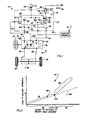
- the apparatus 10 includes an improved priority valve assembly 20 containing a variable size (i.e., flow area) priority flow control orifice 22 which is connected in fluid communication with a hydrostatic steering controller 24 by a conduit 26.
- the steering controller 24 is actuated by rotation of a steering wheel 27 to direct fluid to a power steering motor 28 connected with steerable vehicle wheels 30 and 32.
- a variable size (i.e., area) load sense or main flow control orifice 34 in the controller 24 is closed, and fluid flow through the controller 24 is blocked.
- the load sense orifice 34 is opened and high pressure fluid is directed to a metering unit 35.
- a flow of fluid is directed from the metering unit 35 to either a conduit 36 or a conduit 38 to the motor 28.
- the other one of the two conduits 36 and 38 is connected to fluid reservoir 42 through the controller 24 and a conduit 44. Operation of the motor 28 effects turning movement of the steerable vehicle wheels 30 and 32 in a known manner.
- fluid which is not required for actuation of the power steering apparatus 14 is directed to the auxiliary apparatus 16 through either a variable size (i.e., cross sectional area) main auxiliary flow control orifice 48 (Fig. 1) or both the main auxiliary flow control orifice and a variable size secondary auxiliary flow control orifice 50.
- a variable size i.e., cross sectional area
- main auxiliary flow control orifice 48 Fig. 1
- the main auxiliary flow control orifice 48 is opened and the secondary auxiliary flow control orifice 50 is closed.
- both the main auxiliary flow control orifice 48 and the secondary auxiliary flow control orifice 50 are opened.
- the sizes of the orifices 22, 48 and 50 are varied as a function of variations in the demand for fluid as indicated by the extent to which of the load sense orifice 34 opens to meet the flow requirements of the power steering apparatus 14 during turning of the steerable vehicle wheels 30 and 32.
- a conduit 54 transmits fluid pressure from the upstream side of the load sense orifice 34 to a variable volume chamber 60 at one end of the priority valve assembly 20.
- a conduit 66 transmits fluid pressure from the downstream side of the load sense orifice 34 through a fixed orifice 70 to a variable volume chamber 74 at the end of the priority valve assembly 20 opposite from the variable volume chamber 60.
- the priority valve assembly 20 is thus exposed to a pressure differential which varies as a function of variations in the pressure differential across the load sense orifice 34.
- the load sense orifice 34 When there is a relatively large demand for fluid by the steering controller 24, as during rapid turning of the vehicle wheels 30 and 32, the load sense orifice 34 is fully opened. Increasing the flow area of the orifice 34 decreases the pressure differential across the orifice. The change in the pressure differential is transmitted to the variable volume chambers 60 and 74 and causes the valve 20 to restrict flow to the auxiliary apparatus 16 and increase flow to the steering controller 24. The increased flow to the controller 24 will tend to satisfy the demand for fluid and to increase the pressure differential across the load sense orifice 34. When a steady state is achieved and the demand for fluid flow is being satisfied, the pressure differential across the load sense orifice will be constant and the priority valve assembly 20 will maintain a constant division of flow between the steering controller 24 and the auxiliary apparatus 16.
- the priority valve assembly 20 is responsive to impending demands for fluid.
- a variable size orifice 64 is provided in the steering controller 24.
- the conduit 66 connects the orifice 64 with the a variable volume chamber 74 at one end of the priority valve assembly 20 through a fixed size orifice 70.
- the chamber 74 is supplied with fluid from conduit 26 by way of a pilot orifice 76 and a conduit 68.
- the size of the orifice 64 is relatively large and the pilot flow pressure is relatively low.
- the orifice 64 is reduced in size.
- the reduction in size of orifice 64 causes a rapid increase in pressure in conduit 66 and chamber 74.
- the pressure increase in the chamber 74 effectively decreases the pressure differential to which the priority valve assembly 20 is exposed.
- the change in the pressure differential causes the valve assembly 20 to increase the fluid flow to the load sense orifice 34 in the steering controller 24 by increasing the size of the orifice 22. As the load sense orifice 34 opens, the flow to the controller is already increasing to meet the anticipated steering demand.
- the pilot flow of fluid is combined with the flow from the conduit 26 downstream of the load sense orifice 34 and is directed to the motor 28 through the metering unit 35 of the hydrostatic steering controller 24.
- the manner in which the size of the orifice 64 is reduced to signal the beginning of a steering operation is the same as is described in EP-A-61005.
- the rate of flow of fluid to the auxiliary apparatus 16 varies in the manner indicated by the portion 96 of the curve 82.
- the slope of the portion 96 of the curve 82 is greater than the slope of the portion 88 of the curve. Therefore, when the priority valve assembly 20 has been actuated to a substantial extent, a small change in the extent of actuation of the priority valve assembly results in a relatively large change in the volume of flow of fluid to the auxiliary apparatus 16.
- the different slopes of the portions 88 and 96 of the curve 82 are due to opening of the secondary auxiliary flow control orifice 50 at the point indicated at 100 in Fig. 2.
- the auxiliary flow control orifice 50 is closed, and the volume of fluid flow to the auxiliary apparatus 16 is varied by changing the size of just the main auxiliary flow control orifice 48.
- variations in the extent of actuation of the priority valve assembly 20 varies the size of both of the orifices 48 and 50. This results in a relatively large change in the area through which fluid can flow to the auxiliary apparatus 16 with each incremental change in the extent of actuation of the priority valve assembly 20.
- the open flow area of the orifices 48 and 50 is proportional to the level of fluid flow to the auxiliary apparatus for each portion of the curve 82.
- the priority valve assembly 20 is an apparatus which directs fluid from the pump 12 to the steering controller 24 and to the auxiliary apparatus 16.
- the priority valve assembly 20 divides fluid flow received from the pump 12 through a conduit 106 (see Fig. 1) between the conduits 26 and 80 connected with the steering controller 24 and auxiliary apparatus 16, respectively.
- the priority valve assembly 20 responds quickly to changes in the demand for fluid by the steering controller 24.
- the priority valve assembly 20 is effective to direct a relatively large range of flows of fluid to the auxiliary apparatus 16 through the conduit 80. This enables the apparatus 10 to function smoothly even though the output from the pump 12 varies over a relatively large operating range according to variations in the speed at which the pump is driven.
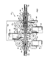
- the priority control valve assembly 20 includes a housing 110 (see Fig. 3) having a bore 112 in which an axially movable valve member 114 is disposed.
- the valve member 114 has cylindrical lands 116, 118 and 120 which cooperate with cylindrical lands 122, 124 and 126 on the housing 110 to define the variable size orifices 22, 48 and 50.
- Opposite axial end portions 128 and 130 of the valve member 114 cooperate with the housing 110 to define the variable volume control chambers 60 and 74 at the ends of the valve member.
- Fluid supplied by the pump 12 enters the housing 110 through the conduit 106.
- the fluid flow from the conduit 106 enters a main housing passage 134 (Fig. 3), which intersects the bore 112 between the cylindrical housing lands 122 and 124. Fluid flow through the main passage 134 is thus directed to the orifice 22 and the orifice 48.
- the valve member 114 When the valve member 114 is in the initial or priority condition shown in Fig. 3, all of the fluid which enters the housing 110 from the conduit 106 flows through the priority flow control orifice 22 to the pilot flow conduit 68 and to a passage 204 and the conduit 26 leading to the steering control valve assembly 24.
- the land 118 on the valve member 114 engages the housing land 124 to block fluid flow through the main auxiliary flow control orifice 48.
- fluid is directed through a housing passage 138 to the secondary auxiliary flow control orifice 50.
- the valve member 114 is in the initial or priority condition illustrated in Fig. 3, the secondary auxiliary flow control orifice 50 is closed.
- the cylindrical valve land 120 is disposed in sealing engagement with the cylindrical housing land 126 to block fluid flow through the variable size orifice 50.
- the left (as viewed in Fig. 3) end portion 128 of the valve member 114 cooperates with a cylindrical housing land 142 to form one end of the variable volume chamber 60.
- the rest of the variable volume chamber 60 is formed by the housing 110 and a fitting 146.
- the variable volume chamber 60 is supplied with fluid through conduit 54 which is connected to the housing 110 by fittings 144 and 146.
- the conduit 54 is also connected with the power steering fluid supply conduit 26 (see Fig. 1).
- a fixed area orifice 152 is provided between the conduit 54 and the variable volume chamber 60 to regulate the rate at which fluid flows to and from the variable volume chamber 60. It should be understood that the conduit 54 and orifice 152 could be placed in the priority valve assembly 20 without outside connections.
- the right (as viewed in Fig. 3) end portion 130 of the valve 114 has a cylindrical land 156 which engages a cylindrical wall 158 of the housing 110 to define one end of the variable volume chamber 74.
- the rest of the chamber 74 is formed by the housing 110 and a fitting 164.
- variable volume chamber 74 is connected with the conduit 66 through a pair of fittings 162 and 164.
- the variable volume chamber 74 is connected with the downstream side of the priority flow control orifice 22 through the passage 68, which is drilled in the housing 110, and the pilot orifice 76, which is also located in the housing.
- the fixed area orifice 70 is provided in the fitting 164 to control the rate at which fluid flows into in the variable volume chamber 74.
- a spring 168 is disposed between the fitting 164 and the end portion 130 of the valve member 114 in a coaxial relationship with the valve member. The spring 168 urges the valve member to an initial or priority condition shown in Fig. 3.
- valve member 114 In addition to being urged to the initial or priority condition shown in Fig. 3 by the spring 168, the valve member 114 is urged to the initial condition by the pressure of fluid in the variable volume chamber 74.
- the variable volume chamber 74 is supplied with fluid pressure through the conduit 68 which is connected with the variable size orifice 64 in the steering controller 24 (see Fig. 1). Therefore the fluid pressure in the chamber 74 to which the end portion 130 of the valve member 114 is exposed varies as a function of variations in the load applied to the steerable vehicle wheels 30 and 32.
- a bypass valve assembly 172 is provided in the valve member 114 in a coaxial relationship with the valve spring 168.
- the bypass valve assembly 172 includes a valve member 176 which is biased to a closed position engaging a valve seat 178 by a biasing spring 180. If the fluid pressure in the chamber 74 should become excessive, the valve member 176 is moved axially toward the left (as viewed in Fig. 3) against the influence of biasing spring 180 to port fluid to radially extending passages 184 formed in the valve member 114 and connected in fluid communication with a valve housing passage 186.
- the valve housing passage 186 is connected with a conduit 188 leading to the reservoir 44.
- the priority valve assembly 20 Prior to starting of the engine which drives the pump 12 (Fig. 1), the priority valve assembly 20 is in the initial or priority condition shown in Fig. 3. There is little or no fluid pressure in the two variable volume chambers 60 and 74. Therefore, the valve member 114 is urged to the initial condition shown in Fig. 3 by the valve spring 168.
- fluid is conducted from the pump through the conduit 106 to the fully opened priority flow control orifice 22.
- the fluid flows through the open orifice 22 to the conduit 26 which is connected to the steering control valve assembly in the controller 24.
- the controller 24 is in its neutral or unactuated condition shown in Fig. 1 and the load sense orifice 34 (Fig. 1) is closed. Therefore, fluid flow from the conduit 26 to the power steering motor 28 is blocked. This results in a fluid pressure differential between the conduit 26 and the conduit 26 being equal to a predetermined control differential pressure.
- the fluid pressure in the conduit 26 is transmitted through the conduit 54 to the variable volume chamber 60 at the left end (as viewed in Fig. 3) of the valve member 114.
- fluid pressure is transmitted from the conduit 26 through the conduit 68 to the fixed orifice 76 (Fig. 1) and the variable volume chamber 74 at the right end (as viewed in Fig. 3) of the valve member 114. Due to a pressure drop caused by the small pilot flow of fluid through the orifice 76, the fluid pressure transmitted to the variable volume chamber 74 is less than the fluid pressure transmitted to the variable volume chamber 60. From the chamber 74, the pilot flow of fluid is directed through the relief orifice 70, conduit 66, the variable orifice 64, and conduit 44 to the reservoir 42.
- the fluid pressure in the variable volume chamber 60 will increase and substantially exceed the fluid pressure transmitted through the fixed orifice 76 to the variable volume chamber 74.
- the fluid pressure in the variable volume chamber 60 will urge the valve member 114 toward the right (as viewed in Fig. 3) against the influence of the biasing spring 168 and the fluid pressure in the variable volume chamber 74. This causes the valve member 114 to shift toward the right from the initial or priority condition shown in Fig. 3 to the intermediate condition shown in Fig. 4.
- valve member 114 When the valve member 114 is in the intermediate condition shown in Fig. 4, the fluid flow from the pump 12 is divided between the auxiliary apparatus 16 and the steering controller 24 by the priority valve assembly 20.
- the flow area of the orifice 22 is reduced from the fully open area shown in Fig. 3 so as to restrict fluid flow to the power steering apparatus 14.
- the orifice 48 is opened to enable fluid to flow through the orifice 48 to a housing passage 200 which connects with the conduit 80 (see Fig. 3).
- the inlet fluid flow received in the valve passage 134 is thus split between the valve passage 200 leading to the auxiliary apparatus supply conduit 80 and the valve passage 204 leading to the power steering system supply conduit 26.
- the valve member 114 will shift through a small distance toward the left from the position shown in Fig. 4 to increase the size of the orifice 22 and reduce the size of the orifice 48. This results in a small increase in the flow of fluid directed to the power steering system 14 and a corresponding reduction in the amount of fluid ported to the auxiliary apparatus 16.
- the valve member 114 Upon termination of the relatively slow turning movement of the steerable vehicle wheels 30 and 32, the valve member 114 will shift through a small distance toward the right to slightly reduce the size of the primary flow control orifice 22 and increase the size of the main auxiliary flow control orifice 48. This results in a small increase in the amount of fluid which is available for the auxiliary apparatus 16.
- the fluid pressure in the conduit 26 will increase.
- the pressure increases despite the continuous pilot flow of fluid through the conduits 68, 66 and 44 to the reservoir 42 because the orifices 76, 70 and 64 restrict the pilot flow.
- the increased fluid pressure in the conduit 26 is transmitted to the variable volume chamber 60 and effects movement of the valve member rightwardly from the position shown in Fig. 4 toward the position shown in Fig. 5 to open the variable size orifice 50.
- Opening the orifice 50 enables the fluid flow to be conducted to the auxiliary apparatus through both of the orifices 48 and 50.
- Incremental movement of the valve member 114 toward either the left or the right (as viewed in Fig. 5) results in a variation in the sizes of both orifices 48 and 50. Therefore, each increment of movement of the valve member 114 results in a relatively large change in the area which is available for fluid to flow to the auxiliary apparatus 16 through the priority valve assembly 20.
- the valve member 94 is now in the range of movement indicated by the portion of the graph designated 94 in Fig. 2.
- the manner in which flow changes with each increment of movement of the valve member is indicated by the portion of the curve 82 designated by the bracket 96 in Fig. 2.
- the priority valve assembly 20 uses only the single orifice 48 to direct fluid to the auxiliary apparatus 16 for relatively small flows from the pump 12 and uses both of the orifices 48 and 50 to direct fluid to the auxiliary apparatus for relatively large flows from the pump 12, the priority valve assembly 20 can smoothly and efficiently handle both large and small rates of flow of fluid. If only the orifice 48 was used to handle all of the fluid flow from the pump 12, either the valve member 114 would have to move through a larger distance in order to handle the maximum flow from the pump or the land 118 would have to be substantially larger in diameter in order to provide the orifice with a flow area capable of handling the maximum flow from the pump. By splitting the flow from the pump between the two orifices 48 and 50, the relatively large flow of fluid can be handled effectively.
- valve member 114 When the valve member 114 is in the fully open condition shown in Fig. 5, the orifice 22 is still open slightly and a small flow of fluid is conducted through the orifice 22. If the valve member 114 should shift to the right through a distance so as to close the orifice 22, the flow of fluid to conduit 26 would be cut off. A loss of flow to conduit 26 will result in a decrease in the fluid pressure in both the variable volume chamber 60 and the variable volume chamber 74. Since both chambers 60 and 74 are continuously connected with the reservoir 42, the fluid in the two chambers would drain out and the pressure would quickly drop. The biasing spring 168 would then be effective to open the orifice 22 slightly to reestablish a flow of fluid to the conduit 26 and the pressure in chambers 60 and 74.
- the fluid pressure in the variable volume chamber 60 varies as a function of the demand for fluid by the power steering system 14. If a steering operation is undertaken with the priority valve member 114 in the position shown in Fig. 5 directing fluid to the auxiliary apparatus through both the orifice 48 and the orifice 50, the fluid pressure in the chamber 60 (Fig. 3) is reduced, as is the pressure differential to which the valve member 114 is exposed. The biasing spring 168 and the fluid pressure in the variable volume chamber 74 will then move the valve member 114 toward the left (as viewed in Fig. 5) to reduce the fluid flow through the open orifices 48 and 50. Depending upon the demand for fluid by the power steering system 14, the valve 114 might move back to the position shown in Fig.
- the size of the orifice 64 is decreased and pilot fluid flow from the conduit 66 is directed to the inlet of the metering unit 35.
- the metering unit 35 is also supplied with fluid from the conduit 26 through the load sense orifice 34.
- the output of the metering unit 35 is directed to the expanding chamber of the power steering motor 28.
- the fluid from the contracting chamber of the power steering motor is directed to reservoir.
- the pilot fluid flow through chamber 74 is blocked at the orifice. This provides an increase in pressure in chamber 74 which differs from the steering motor inlet pressure by an amount corresponding to the pressure drop across the orifice 76.
- the increased pilot fluid pressure assists the biasing spring 68 in moving the valve member 114 from the position shown in Fig. 5 toward the position shown in Figs. 3 and 4.
- auxiliary apparatus 16 encounters a sudden increase in its load when the orifices 48 and/or 50 are open, the increase in fluid pressure is transmitted through the priority control orifice 22 to the conduit 26.
- the increased fluid pressure in the conduit 26 is transmitted to the variable volume chamber 60 and urges the valve member 114 toward the right (as viewed in Fig. 3). Movement of valve member 114 momentarily reduces the pilot flow and steering flow of fluid to enable the auxiliary apparatus to overcome the sudden increase the load applied to the auxiliary apparatus.
- the increase in fluid pressure transmitted to the auxiliary apparatus 16 is relatively short in duration.
- the fluid pressure in the variable volume chamber 60 is soon reduced to a level at which the spring 168 moves the valve member 114 back toward the left to increase the size of the variable orifice 22 and maintain the desired flow through the conduit 26.
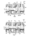
- the priority valve assembly has a single orifice 22 through which fluid is directed to the power steering apparatus 14.
- a pair of variable size orifices to direct fluid to the power steering apparatus 14.
- a pair of variable size orifices is used to control fluid flow to the power steering apparatus 14 and a second pair of variable size orifices is used to control fluid flow to the auxiliary apparatus. Since the embodiment of the priority valve assembly illustrated in Fig. 6 is similar to the priority valve assembly illustrated in Fig. 3, similar numerals will be utilized to designate similar components, the suffix letter "a" being added to the embodiment shown in Fig. 6 in order to avoid confusion.
- the priority valve assembly 20a of Fig. 6 includes two variable size orifices 48a and 50a which direct fluid flow to the auxiliary apparatus 16 in the same manner as described in connection with the embodiment of the priority valve assembly 20 shown in Fig. 3.
- two orifices 220 and 222 are used to control the flow of fluid to the steering controller 24.
- the orifice 222 is a main priority flow control orifice and is open when either relatively large or small flows of fluid are directed to the steering fluid supply conduit 26a.
- the variable size orifice 220 is a secondary priority flow control orifice and is open only when relatively large flows of fluid are to be conducted to the power steering fluid supply conduit 26a.
- the priority valve assembly 20a includes a valve member 114a having an end portion 128a which cooperates with the housing 110a to form a variable volume chamber 60a.
- the variable volume chamber 60a is connected in fluid communication with the power steering fluid supply conduit 26a through fittings 144a and 146a. Therefore, the fluid pressure in the variable volume chamber 60a varies as a function of the demand for fluid by the steering controller 24.
- the fluid pressure in the conduit 26a and the variable volume chamber 60a decreases. This results in movement of the valve member 114a toward the left (as viewed in Fig. 6) to increase the flow area available through the orifices 220 and 222 and thereby tend to satisfy the demand for fluid by the power steering system. At the same time, the flow areas through the orifices 48a and 50a are decreasing to decrease the flow of fluid conducted to the auxiliary apparatus. Conversely, if the demand for fluid by the power steering apparatus 14 decreases, the pressure in the conduit 26a increases with a resulting increase in the fluid pressure in the variable volume chamber 60a. This shifts the valve member 114a toward the right (as viewed in Fig. 6) to decrease the sizes of the orifices 220 and 222 and increase the sizes of the orifices 48a and 50a.
- variable volume chamber 74a The variable volume chamber 74a is connected in fluid communication with a source of pilot fluid pressure which is increased to signal the initiation of a steering operation and an impending demand for fluid by the steering controller 24. The manner in which this is accomplished is the same as was previously explained in connection with the embodiment of the invention shown in Fig. 3.
- a biasing spring 168a is provided in the variable volume chamber 74a to urge the valve member toward the left to the position shown in Fig. 6 in conjunction with the pilot fluid pressure in the variable volume chamber 74a.
Landscapes
- Engineering & Computer Science (AREA)
- Mechanical Engineering (AREA)
- Physics & Mathematics (AREA)
- Fluid Mechanics (AREA)
- General Engineering & Computer Science (AREA)
- Chemical & Material Sciences (AREA)
- Combustion & Propulsion (AREA)
- Transportation (AREA)
- Power Steering Mechanism (AREA)
- Servomotors (AREA)
- Fluid-Pressure Circuits (AREA)
Applications Claiming Priority (2)
| Application Number | Priority Date | Filing Date | Title |
|---|---|---|---|
| US36185182A | 1982-03-25 | 1982-03-25 | |
| US361851 | 1982-03-25 |
Publications (3)
| Publication Number | Publication Date |
|---|---|
| EP0090129A2 EP0090129A2 (en) | 1983-10-05 |
| EP0090129A3 EP0090129A3 (en) | 1984-03-28 |
| EP0090129B1 true EP0090129B1 (en) | 1986-09-03 |
Family
ID=23423680
Family Applications (1)
| Application Number | Title | Priority Date | Filing Date |
|---|---|---|---|
| EP19830100351 Expired EP0090129B1 (en) | 1982-03-25 | 1983-01-17 | Fluid flow control apparatus |
Country Status (6)
| Country | Link |
|---|---|
| EP (1) | EP0090129B1 (da) |
| JP (1) | JPH0662089B2 (da) |
| BR (1) | BR8300848A (da) |
| CA (1) | CA1193972A (da) |
| DE (1) | DE3365745D1 (da) |
| DK (1) | DK155341C (da) |
Families Citing this family (6)
| Publication number | Priority date | Publication date | Assignee | Title |
|---|---|---|---|---|
| US4616671A (en) * | 1984-01-27 | 1986-10-14 | Trw Inc. | Valve with flow force compensator |
| FR2585633A1 (fr) * | 1985-07-30 | 1987-02-06 | Valeo | Generateur de chaleur pour vehicule automobile |
| JPH02504541A (ja) * | 1987-04-04 | 1990-12-20 | ツァーンラトファブリック フリードリッヒシャーフェン アクチエン ゲゼルシャフト | 特に自動車の応荷重変速機構用の、流体圧力調整装置 |
| DE3814508A1 (de) * | 1988-04-29 | 1989-11-09 | Danfoss As | Hydrostatische lenkeinrichtung |
| JP2670296B2 (ja) * | 1988-05-26 | 1997-10-29 | 株式会社アマダ | 制御弁 |
| DE19908614C1 (de) * | 1999-02-27 | 2000-09-21 | Rexroth Hydraulik Parchim Gmbh | Prioritätsventil für einen hydraulischen Lenkkreislauf |
Family Cites Families (8)
| Publication number | Priority date | Publication date | Assignee | Title |
|---|---|---|---|---|
| US3916932A (en) * | 1974-03-28 | 1975-11-04 | Eaton Corp | Flow divider valve assembly |
| US3996742A (en) * | 1976-03-04 | 1976-12-14 | Trw Inc. | Fluid flow control apparatus |
| IT1077304B (it) * | 1976-06-23 | 1985-05-04 | Eaton Corp | Regolatore per dispositivi azionati dalla pressione di un fluido |
| DE2716868C2 (de) * | 1977-04-16 | 1984-03-08 | Zahnradfabrik Friedrichshafen Ag, 7990 Friedrichshafen | Druckmittelsteuereinrichtung |
| DE2738483A1 (de) * | 1977-08-26 | 1979-03-01 | Zahnradfabrik Friedrichshafen | Steuereinrichtung, insbesondere fuer kraftfahrzeuge |
| US4215720A (en) * | 1978-10-02 | 1980-08-05 | General Signal Corporation | Fluid control valve system |
| US4253382A (en) * | 1979-09-07 | 1981-03-03 | Eaton Corporation | Steering valve assembly for steering and brake system |
| US4665695A (en) * | 1981-03-13 | 1987-05-19 | Trw Inc. | Hydrostatic load sense steering system |
-
1983
- 1983-01-13 CA CA000419376A patent/CA1193972A/en not_active Expired
- 1983-01-17 EP EP19830100351 patent/EP0090129B1/en not_active Expired
- 1983-01-17 DE DE8383100351T patent/DE3365745D1/de not_active Expired
- 1983-02-22 DK DK75383A patent/DK155341C/da not_active IP Right Cessation
- 1983-02-22 BR BR8300848A patent/BR8300848A/pt not_active IP Right Cessation
- 1983-03-25 JP JP58050309A patent/JPH0662089B2/ja not_active Expired - Lifetime
Also Published As
| Publication number | Publication date |
|---|---|
| DK75383D0 (da) | 1983-02-22 |
| JPH0662089B2 (ja) | 1994-08-17 |
| BR8300848A (pt) | 1983-11-16 |
| DK75383A (da) | 1983-09-26 |
| DE3365745D1 (en) | 1986-10-09 |
| EP0090129A2 (en) | 1983-10-05 |
| CA1193972A (en) | 1985-09-24 |
| JPS58185372A (ja) | 1983-10-29 |
| EP0090129A3 (en) | 1984-03-28 |
| DK155341B (da) | 1989-03-28 |
| DK155341C (da) | 1989-09-11 |
Similar Documents
| Publication | Publication Date | Title |
|---|---|---|
| US4473128A (en) | Vehicular power steering system | |
| US4420934A (en) | Automotive vehicle hydraulic system | |
| US4566477A (en) | Fluid flow control apparatus | |
| US3996742A (en) | Fluid flow control apparatus | |
| JPH0698929B2 (ja) | 加圧流体流制御システム | |
| US4759419A (en) | Vehicle speed responsive power steering assembly | |
| US4768605A (en) | Apparatus for use in a power steering system | |
| JPH0316305B2 (da) | ||
| US5567123A (en) | Pump displacement control for a variable displacement pump | |
| US4784235A (en) | Oil pressure reaction control valve for power steering apparatus | |
| US5561979A (en) | Control arrangement for a hydrostatic system | |
| US3641879A (en) | Central hydraulic system for a vehicle | |
| EP0090129B1 (en) | Fluid flow control apparatus | |
| JPH0465247B2 (da) | ||
| US4507920A (en) | Steering control apparatus | |
| EP0607108B1 (en) | A method for controlling a hydraulic motor and a hydraulic valve therefor | |
| US4365473A (en) | Hydrostatic transmission having an overspeed control | |
| EP0802106B1 (en) | Flow rate controller in power steering apparatus | |
| EP0158450A1 (en) | Demand-responsive flow control valve mechanism | |
| JPH08270789A (ja) | 油圧可変容量形ポンプの自動車方式駆動制御装置 | |
| US5158149A (en) | Steering force control apparatus for power steering system | |
| JPH0118460Y2 (da) | ||
| WO1982000617A1 (en) | Hydrostatic transmission having an overspeed control | |
| JPH0744774Y2 (ja) | 可変容量形ポンプの制御装置 | |
| JPH0137974Y2 (da) |
Legal Events
| Date | Code | Title | Description |
|---|---|---|---|
| PUAI | Public reference made under article 153(3) epc to a published international application that has entered the european phase |
Free format text: ORIGINAL CODE: 0009012 |
|
| AK | Designated contracting states |
Designated state(s): DE GB IT SE |
|
| PUAL | Search report despatched |
Free format text: ORIGINAL CODE: 0009013 |
|
| RHK1 | Main classification (correction) |
Ipc: F15B 13/07 |
|
| AK | Designated contracting states |
Designated state(s): DE GB IT SE |
|
| 17P | Request for examination filed |
Effective date: 19840907 |
|
| GRAA | (expected) grant |
Free format text: ORIGINAL CODE: 0009210 |
|
| AK | Designated contracting states |
Kind code of ref document: B1 Designated state(s): DE GB IT SE |
|
| REF | Corresponds to: |
Ref document number: 3365745 Country of ref document: DE Date of ref document: 19861009 |
|
| ITF | It: translation for a ep patent filed |
Owner name: STUDIO TORTA SOCIETA' SEMPLICE |
|
| PLBE | No opposition filed within time limit |
Free format text: ORIGINAL CODE: 0009261 |
|
| STAA | Information on the status of an ep patent application or granted ep patent |
Free format text: STATUS: NO OPPOSITION FILED WITHIN TIME LIMIT |
|
| 26N | No opposition filed | ||
| PG25 | Lapsed in a contracting state [announced via postgrant information from national office to epo] |
Ref country code: SE Effective date: 19880118 |
|
| PGFP | Annual fee paid to national office [announced via postgrant information from national office to epo] |
Ref country code: GB Payment date: 19891231 Year of fee payment: 8 |
|
| PG25 | Lapsed in a contracting state [announced via postgrant information from national office to epo] |
Ref country code: GB Effective date: 19910117 |
|
| GBPC | Gb: european patent ceased through non-payment of renewal fee | ||
| EUG | Se: european patent has lapsed |
Ref document number: 83100351.2 Effective date: 19880913 |
|
| PGFP | Annual fee paid to national office [announced via postgrant information from national office to epo] |
Ref country code: DE Payment date: 20011219 Year of fee payment: 20 |