EP0089824B2 - Verfahren zum Zerlegen, Pressen und Schneiden eines Skeletts eines verbrauchten Kernbrennstoffbündels. - Google Patents
Verfahren zum Zerlegen, Pressen und Schneiden eines Skeletts eines verbrauchten Kernbrennstoffbündels. Download PDFInfo
- Publication number
- EP0089824B2 EP0089824B2 EP19830301510 EP83301510A EP0089824B2 EP 0089824 B2 EP0089824 B2 EP 0089824B2 EP 19830301510 EP19830301510 EP 19830301510 EP 83301510 A EP83301510 A EP 83301510A EP 0089824 B2 EP0089824 B2 EP 0089824B2
- Authority
- EP
- European Patent Office
- Prior art keywords
- skeleton
- assembly
- bottom nozzle
- fuel
- compacted
- Prior art date
- Legal status (The legal status is an assumption and is not a legal conclusion. Google has not performed a legal analysis and makes no representation as to the accuracy of the status listed.)
- Expired - Lifetime
Links
Images


Classifications
-
- G—PHYSICS
- G21—NUCLEAR PHYSICS; NUCLEAR ENGINEERING
- G21C—NUCLEAR REACTORS
- G21C19/00—Arrangements for treating, for handling, or for facilitating the handling of, fuel or other materials which are used within the reactor, e.g. within its pressure vessel
- G21C19/34—Apparatus or processes for dismantling nuclear fuel, e.g. before reprocessing ; Apparatus or processes for dismantling strings of spent fuel elements
- G21C19/36—Mechanical means only
-
- B—PERFORMING OPERATIONS; TRANSPORTING
- B41—PRINTING; LINING MACHINES; TYPEWRITERS; STAMPS
- B41B—MACHINES OR ACCESSORIES FOR MAKING, SETTING, OR DISTRIBUTING TYPE; TYPE; PHOTOGRAPHIC OR PHOTOELECTRIC COMPOSING DEVICES
- B41B21/00—Common details of photographic composing machines of the kinds covered in groups B41B17/00 and B41B19/00
-
- B—PERFORMING OPERATIONS; TRANSPORTING
- B41—PRINTING; LINING MACHINES; TYPEWRITERS; STAMPS
- B41B—MACHINES OR ACCESSORIES FOR MAKING, SETTING, OR DISTRIBUTING TYPE; TYPE; PHOTOGRAPHIC OR PHOTOELECTRIC COMPOSING DEVICES
- B41B27/00—Control, indicating, or safety devices or systems for composing machines of various kinds or types
- B41B27/28—Control, indicating, or safety devices for individual operations or machine elements
-
- Y—GENERAL TAGGING OF NEW TECHNOLOGICAL DEVELOPMENTS; GENERAL TAGGING OF CROSS-SECTIONAL TECHNOLOGIES SPANNING OVER SEVERAL SECTIONS OF THE IPC; TECHNICAL SUBJECTS COVERED BY FORMER USPC CROSS-REFERENCE ART COLLECTIONS [XRACs] AND DIGESTS
- Y02—TECHNOLOGIES OR APPLICATIONS FOR MITIGATION OR ADAPTATION AGAINST CLIMATE CHANGE
- Y02E—REDUCTION OF GREENHOUSE GAS [GHG] EMISSIONS, RELATED TO ENERGY GENERATION, TRANSMISSION OR DISTRIBUTION
- Y02E30/00—Energy generation of nuclear origin
- Y02E30/30—Nuclear fission reactors
-
- Y—GENERAL TAGGING OF NEW TECHNOLOGICAL DEVELOPMENTS; GENERAL TAGGING OF CROSS-SECTIONAL TECHNOLOGIES SPANNING OVER SEVERAL SECTIONS OF THE IPC; TECHNICAL SUBJECTS COVERED BY FORMER USPC CROSS-REFERENCE ART COLLECTIONS [XRACs] AND DIGESTS
- Y02—TECHNOLOGIES OR APPLICATIONS FOR MITIGATION OR ADAPTATION AGAINST CLIMATE CHANGE
- Y02W—CLIMATE CHANGE MITIGATION TECHNOLOGIES RELATED TO WASTEWATER TREATMENT OR WASTE MANAGEMENT
- Y02W30/00—Technologies for solid waste management
- Y02W30/50—Reuse, recycling or recovery technologies
-
- Y—GENERAL TAGGING OF NEW TECHNOLOGICAL DEVELOPMENTS; GENERAL TAGGING OF CROSS-SECTIONAL TECHNOLOGIES SPANNING OVER SEVERAL SECTIONS OF THE IPC; TECHNICAL SUBJECTS COVERED BY FORMER USPC CROSS-REFERENCE ART COLLECTIONS [XRACs] AND DIGESTS
- Y10—TECHNICAL SUBJECTS COVERED BY FORMER USPC
- Y10S—TECHNICAL SUBJECTS COVERED BY FORMER USPC CROSS-REFERENCE ART COLLECTIONS [XRACs] AND DIGESTS
- Y10S83/00—Cutting
- Y10S83/929—Particular nature of work or product
- Y10S83/93—Radioactive
-
- Y—GENERAL TAGGING OF NEW TECHNOLOGICAL DEVELOPMENTS; GENERAL TAGGING OF CROSS-SECTIONAL TECHNOLOGIES SPANNING OVER SEVERAL SECTIONS OF THE IPC; TECHNICAL SUBJECTS COVERED BY FORMER USPC CROSS-REFERENCE ART COLLECTIONS [XRACs] AND DIGESTS
- Y10—TECHNICAL SUBJECTS COVERED BY FORMER USPC
- Y10T—TECHNICAL SUBJECTS COVERED BY FORMER US CLASSIFICATION
- Y10T29/00—Metal working
- Y10T29/53—Means to assemble or disassemble
- Y10T29/531—Nuclear device
-
- Y—GENERAL TAGGING OF NEW TECHNOLOGICAL DEVELOPMENTS; GENERAL TAGGING OF CROSS-SECTIONAL TECHNOLOGIES SPANNING OVER SEVERAL SECTIONS OF THE IPC; TECHNICAL SUBJECTS COVERED BY FORMER USPC CROSS-REFERENCE ART COLLECTIONS [XRACs] AND DIGESTS
- Y10—TECHNICAL SUBJECTS COVERED BY FORMER USPC
- Y10T—TECHNICAL SUBJECTS COVERED BY FORMER US CLASSIFICATION
- Y10T83/00—Cutting
- Y10T83/04—Processes
- Y10T83/0405—With preparatory or simultaneous ancillary treatment of work
- Y10T83/0419—By distorting within elastic limit
- Y10T83/0429—By compressing
-
- Y—GENERAL TAGGING OF NEW TECHNOLOGICAL DEVELOPMENTS; GENERAL TAGGING OF CROSS-SECTIONAL TECHNOLOGIES SPANNING OVER SEVERAL SECTIONS OF THE IPC; TECHNICAL SUBJECTS COVERED BY FORMER USPC CROSS-REFERENCE ART COLLECTIONS [XRACs] AND DIGESTS
- Y10—TECHNICAL SUBJECTS COVERED BY FORMER USPC
- Y10T—TECHNICAL SUBJECTS COVERED BY FORMER US CLASSIFICATION
- Y10T83/00—Cutting
- Y10T83/04—Processes
- Y10T83/0448—With subsequent handling [i.e., of product]
Definitions
- This invention relates to a method for dismantling, shearing, and compacting a fuel assembly frame skeleton.
- US-A-3,763,770 proposes to shear spent nuclear fuel bundles into units of predetermined length.
- This apparatus generally includes a pair of orthogonally related "gags" to clamp and collapse the bundle or a pair of parallely-acting horizontal gags co-operating with a vertical restraint for compressing predetermined lengths of the fuel bundles. Then a shear blade is used to sever predetermined lengths which are dropped through a chute to a dissolution apparatus.
- US-A-4,056,052 to Weil et al. is concerned with a method for shearing spent nuclear fuel assemblies of the shrouded pin-type wherein a plurality of long metal tubes packed with ceramic fuel are supported in a spaced-apart relationship.
- Spent fuel nuclear assemblies are first compacted between specially provided gag compactors into short segments so that they are amenable to chemical processing. Compression takes place so as to form the assemblies into specially formed compacts. Shearing then takes place with specially contoured blades which are adapted to mate with the contoured surface of the compacts of the compressed fuel assemblies.
- a method for remotely dismantling, compacting and shearing a spent fuel assembly frame skeleton is known from document FR-A-2 324 094, wherein the assembly skeleton comprising the bottom nozzle, thimble tubes and grids is removed from the spent fuel pit and placed into a shearing device in which the bottom nozzle is removed from the assembly skeleton, sections of the assembly skeleton are compacted in a direction normal to the longitudinal axis of the skeleton, and each compacted section is cut before the next section is compacted, whereby individual pieces of compacted skeleton are formed so as to reduce the length of the compacted skeleton.
- the present invention resides in a method for remotely dismantling, compacting and shearing a spent fuel assembly frame skeleton, wherein, after the top nozzle and the fuel rods have been removed from the fuel assembly in a spent fuel pit, the assembly skeleton comprising the bottom nozzle, thimble tubes and grids is moved from the spent fuel pit and placed into a bottom nozzle removal fixture of a skeleton conveyor, in which removal fixture the bottom nozzle is removed from the assembly skeleton, the assembly skeleton is then conveyed from the bottom nozzle removal fixture to a compactor separate from the bottom nozzle removal fixture, wherein the remainder of the assembly skeleton is compacted in a direction normal to the longitudinal axis of the skeleton, and the compacted skeleton is conveyed from the compactor to a skeleton shear separate from the compactor, in which the compacted assembly skeleton is cut into individual pieces so as to reduce the length of the compacted skeleton.
- the skeleton is compacted so that a cross-section taken along its axial length is 5 cm x 25 cm.
- the individual portions After compacting and shearing into 40 cm lengths along the axial length of the skeleton, the individual portions are fed by means of a chute to the scrap transfer bin, also under water and supported by the superstructure.
- the compacted and sheared skeleton assembly may also be placed into a container which is adapted to hold four skeletons for off-site removal.
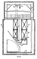
- a spent fuel assembly 2 including fuel rods 6, top nozzle 8 and fuel cell assembly frame skeleton 10 (Fig 2) is intended to hang in the transfer canal 12 (fig 1) adjacent to the spent fuel pit 14 of the fuel-handling building 16. Connecting fuel transfer canal 12 and spent fuel pit 14 is fuel handling slot 18.
- a skeleton conveyor 20 which generally includes as components a nozzle shear or removal fixture 22, a compactor 24, and a skeleton shear 26. All of the aforesaid components are supported within a frame 28 which hangs from the curb 31 of the transfer canal 12 of the spent fuel pit 14.
- a transfer container or scrap storage bin 30 is supported at the bottom of the frame 28 to receive compacted skeleton pieces 32 (see Fig 3) and the bottom nozzle 34.
- Spent fuel assemblies 2 are dismantled, and the fuel rods 6 and top nozzle 8 are removed therefrom to leave the fuel cell frame skeleton 10 in spent fuel pit 14.
- a crane mechanism 36 (Fig 5) is slidable on casters 38 along and on top of ledges or wall 40 to the transfer canal 12, adjacent the spent fuel pit 14, to raise the fuel cell assembly frame skeleton 10 from the fuel pit 14 and move it to the skeleton conveyor 20.
- skeleton 10 is lifted by a long-handled tool held by jib crane 46.
- the long-handled tool also may be suspended from the spent fuel pit bridge or a wall of the spent fuel pit 14. Then skeleton 10 can be picked up by a floor or wall-mounted jib crane 52 (Fig 4) and transferred to the skeleton conveyor.
- the jib crane 52 may be in the form of a long-armed crane which is pivoted on a pivot connection such as pivot connection 54 on ledge or curb 31 adjacent to transfer canal 12, and may be pivoted over the canal and skeleton conveyor 20 towards fuel pit 14 to pick up skeleton 10 and place it into skeleton conveyor 20 for compaction.
- the bottom 33 of transfer canal 12 is desirably 914 cm (30 feet) below curb 31, and the bottom of the spent fuel pit 14 is about 1219 cm (40 feet) below curb 31.
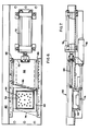
- bottom nozzle shear or removal fixture 22 generally includes a frame structure 60 carrying a bottom nozzle support 62 for supporting bottom nozzle 34 after frame skeleton 10 is lowered by crane mechanism 36 or long arm 52 into frame structure 60. Also supported for movement transversely to the longitudinal axis of the thimble tubes 44, when bottom nozzle 34 is on support 62, is a guillotine blade 64 slidably arranged for controlled and guided movement in oppositely arranged spaced guide and support channels or guideways 66.
- the front end 68 is angled to its direction of movement, and the rear end 70 is connected with hydraulic cylinder 72 which, when actuated, moves to the dot-dashed position 74 of blade 64 across the top of bottom nozzle 34 for separation thereof from thimbles 44.
- bottom door 76 is operated by air cylinder 78 to permit nozzle 34 to drop out of bottom nozzle support 62 into container 30 by means of chute or slide 79 (Fig 1).
- Guillotine blade 64 is strong enough to shear off the bottom nozzle by brute force, free of flying materials.
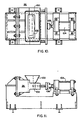
- skeleton 10 which now consists of only thimble tubes 44 and grids 42 is then moved by crane mechanism 36 into position above compactor 24. At this station, the remainder of skeleton 10 is reduced in width from about 21.6 cm (8.5 inches) to about 5.08 cm (2 inches).
- compactor 24 includes a receiving area 80 for receiving the remainder of skeleton 10 composed of grids 42 and thimble tube 44.
- Receiving area 80 is surrounded by a bearing plate 82 on one side and opposite thereto is a ram plate 84 which is guided for movement by guideways or guide bars 86.
- Ram plate 84 is movable from its position shown in full outline to the position shown in dot-dashed outline 84'.
- temporary support 90 is provided which is pivotally connected at pivot 92 to compactor 24 and is swung into place by means of air cylinder 94 when actuated from its neutral position 96 indicated in dashed outline.
- crane mechanism 36 or long-armed crane 52 moves the compacted assembly to skeleton shear 26, or shear for the skeleton unit after the bottom nozzle has been removed, which includes a funnel-shaped member or container 100 with a shear blade 102 and a hydraulic cylinder 104 connected to blade 102 by means of connecting rod 106 connected at one end to blade 102 and the other end to hydraulic cylinder 104.
- the individual operating parts and movement means of the skeleton shear are conventional.
- Blade 102 is contoured to sever the thimble tubes to form small units for placement into scrap storage bin 30. After the shear blade 102 cuts the thimbles into short pieces, they fall down a chute 108 (Fig 1) and end up in a temporary scrap storage bin or transfer container 30.
- the frame or superstructure 28 is desirably made to fill within the transfer canal 12, and it is suitably enclosed to prevent debris from falling into the canal or the skeleton conveyor 20.
- the skeleton assembly 10 in its various stages of processing be held by the crane mechanism 36 or long-armed crane 54 as the assembly is moved from compactor 24 to skeleton shear 26.
- Cutting of the thimble tubes 44 preferably takes place at or near a grid 42.
- the crane should be preferably 609 cm (20 feet) above curb 31 to provide for ease of transfer from spent fuel pit 14 to transfer canal 12.
- Cutting should desirably take place along a plane which is perpendicular or orthogonally related to the longitudinal axis of the fuel cell assembly 2.
- frame structure 28 may be provided with another container such as container 30 adjacent chute 79 so as to separate the bottom nozzles from the remainder of skeleton 10 which is to be compacted and disposed of separate from the bottom nozzle.
- the thimble tubes 44 are severed from the top nozzle 8 by cutting the thimble tubes 44 from the top nozzle to expose the fuel rods. The fuel rods are then removed from the bottom nozzle grid assembly. In many instances, the top nozzle 8 and the fuel rods 6 can be reused, and the cutting to remove top nozzle 8 is carried out in the fuel pit 14.
Landscapes
- Physics & Mathematics (AREA)
- Engineering & Computer Science (AREA)
- Plasma & Fusion (AREA)
- General Engineering & Computer Science (AREA)
- High Energy & Nuclear Physics (AREA)
- Processing Of Solid Wastes (AREA)
- Automobile Manufacture Line, Endless Track Vehicle, Trailer (AREA)
- Working Measures On Existing Buildindgs (AREA)
Claims (6)
- Verfahren zum Fern-Abbauen, Verdichten und Zerschneiden eines verbrauchten Brennsatzes eines Rahmengerüsts (10), worin nach dem Entfernen der oberen Düse (8) und der Brennstäbe (6) vom Brennsatz in einem verbrauchten Brennschacht (14), das Gerüst (10) mit der unteren Düse (34), den Fingerhutröhren (44) und den Gittern (42) aus den verbrauchten Brennschacht (14) entfernt und in einen Ausziehkäfig (22) einer Demontier oder Gerüsttransportvorrichtung (20) gebracht wird, in dem Ausziehkäfig die untere Düse (34) aus dem Gerüst (10) genommen wird, worauf dieses Gerüst (10) dann von dem Ausziehkäfig (22) zu einem Verdichter (24) der von dem Ausziehkäfig (22) getrennt ist, bewegt wird, in dem der Rest des Gerüsts (10) in eine Richtung senkrecht zu der Längsachse des Gerüsts (10) verdichtet und dieses verdichtete Gerüst (10) von dem Verdichter (24) zu einem Gerüstschneider (26) transportiert und darin in einzelne Stücke geschnitten wird, um die Länge des verdichteten Gerüsts zu reduzieren.
- Verfahren nach Anspruch 1, dadurch gekennzeichnet, dass die untere Düse (34) vom Gerüst (10) mit einem Fallmesser (64) abgeschnitten wird und in einen Transportbehälter (30) fällt.
- Verfahren nach Anspruch 2, dadurch gekennzeichnet, dass das Gerüst (10) bis auf einen Querschnittsbereich von 5 x 25 m in orthogonaler Richtung zur Längsachse des Brennsatzgerüsts (10) verdichtet wird.
- Verfahren nach Anspruch 3, dadurch gekennzeichnet, dass das verdichtete Gerüst (10) in Stücke von 40 cm Länge zerschnitten wird.
- Verfahren nach einem der Ansprüche 1 bis 4, dadurch gekennzeichnet, dass die untere Düse (34) über eine Rinne (79) zu einem Transportbehälter (30) transportiert wird, wobei die Rinne an der Demontiervorrichtung (20) zwischen dem Ausziehkäfig (22) und dem Transportbehälter (30) angeordnet ist.
- Verfahren nach Anspruch 5, dadurch gekennzeichnet, dass vor dem Transport des Rests des Brennsatzgerüsts (10) vom verbrauchten Brennschacht (14) zum Förderkanal (12) mit Wasser soweit gefüllt wird, dass der Wasser spiegel über dem Ausziehkäfig (22) für die untere Düse, dem Verdichter (24), der Gerüstschneidevorrichtung (26) und dem Behäalter (30) liegt.
Applications Claiming Priority (2)
| Application Number | Priority Date | Filing Date | Title |
|---|---|---|---|
| US359552 | 1982-03-18 | ||
| US06/359,552 US4511499A (en) | 1982-03-18 | 1982-03-18 | Apparatus for dismantling and disposing of fuel assemblies |
Publications (3)
| Publication Number | Publication Date |
|---|---|
| EP0089824A1 EP0089824A1 (de) | 1983-09-28 |
| EP0089824B1 EP0089824B1 (de) | 1986-11-12 |
| EP0089824B2 true EP0089824B2 (de) | 1993-12-15 |
Family
ID=23414312
Family Applications (1)
| Application Number | Title | Priority Date | Filing Date |
|---|---|---|---|
| EP19830301510 Expired - Lifetime EP0089824B2 (de) | 1982-03-18 | 1983-03-18 | Verfahren zum Zerlegen, Pressen und Schneiden eines Skeletts eines verbrauchten Kernbrennstoffbündels. |
Country Status (9)
| Country | Link |
|---|---|
| US (1) | US4511499A (de) |
| EP (1) | EP0089824B2 (de) |
| JP (1) | JPS58172593A (de) |
| KR (1) | KR840004294A (de) |
| BE (1) | BE896192A (de) |
| CA (1) | CA1193767A (de) |
| DE (1) | DE3367691D1 (de) |
| ES (1) | ES520731A0 (de) |
| FR (1) | FR2523755B1 (de) |
Cited By (1)
| Publication number | Priority date | Publication date | Assignee | Title |
|---|---|---|---|---|
| DE102005013984B3 (de) * | 2005-02-04 | 2006-08-03 | Framatome Anp Gmbh | Vorrichtung und Verfahren zum Konditionieren eines Brennelementskelettes eines Kernreaktors |
Families Citing this family (17)
| Publication number | Priority date | Publication date | Assignee | Title |
|---|---|---|---|---|
| FR2528218A1 (fr) * | 1982-06-07 | 1983-12-09 | Transnucleaire | Procede, installation et dispositif pour le compactage d'objets oblongs et flexibles notamment des crayons combustibles de reacteur nucleaire |
| US4537711A (en) * | 1983-01-05 | 1985-08-27 | Westinghouse Electric Corp. | Fuel assembly skeleton compaction |
| JPS59187298A (ja) * | 1983-04-08 | 1984-10-24 | 株式会社日立製作所 | 高放射性固体廃棄物の切断装置 |
| JPS60123799A (ja) * | 1983-12-08 | 1985-07-02 | 株式会社神戸製鋼所 | 使用済燃料内挿物の減容処理装置 |
| US4673545A (en) * | 1984-11-06 | 1987-06-16 | Advanced Nuclear Fuels Corporation | Remotely controlled apparatus for removing clips from irradiated nuclear fuel assemblies |
| US4648989A (en) * | 1985-02-27 | 1987-03-10 | Wastechem Corporation | Underwater compressing and cutting apparatus |
| US4747995A (en) * | 1985-06-10 | 1988-05-31 | Widder Corporation | Velocity limiter shear for BWR control rods |
| FR2600202A1 (fr) * | 1986-06-12 | 1987-12-18 | Transnucleaire | Dispositif modulaire de compactage sous eau d'assemblages combustibles nucleaires |
| DE3802966A1 (de) * | 1987-10-02 | 1989-04-20 | Wiederaufarbeitung Von Kernbre | Verfahren und vorrichtung zur behandlung eines von brennstaeben befreiten brennelementskelettes eines bestrahlten kernreaktorbrennelementes |
| FR2632765B1 (fr) * | 1988-06-10 | 1994-04-08 | Framatome | Dispositif de compactage de squelette d'assemblage combustible nucleaire |
| DE3834269C1 (de) * | 1988-10-08 | 1990-01-04 | Thyssen Industrie Ag, 4300 Essen, De | |
| DE4031153A1 (de) * | 1990-10-03 | 1992-04-09 | Nuklear Service Gmbh Gns | Anlage fuer die zerkleinerung von radioaktiv kontaminierten brennelementkaesten |
| FR2673033B1 (fr) * | 1991-02-19 | 1994-07-22 | Framatome Sa | Procede et dispositif de demantelement des equipements internes d'un reacteur nucleaire refroidi par de l'eau. |
| GB9203268D0 (en) * | 1992-02-15 | 1992-04-15 | British Nuclear Fuels Plc | A metering system |
| FR2825830B1 (fr) * | 2001-06-12 | 2003-12-12 | Framatome Anp | Procede et dispositif d'elimination d'un squelette irradie d'un assemblage de combustible d'un reacteur nucleaire |
| FR2825831B1 (fr) * | 2001-06-12 | 2003-09-19 | Framatome Anp | Procede et dispositif d'elimination, sous forme compacte, d'un squelette irradie d'un assemblage de combustible d'un reacteur nucleaire |
| US9514852B2 (en) * | 2011-11-21 | 2016-12-06 | Westinghouse Electric Company Llc | Method to reduce the volume of boiling water reactor fuel channels for storage |
Family Cites Families (9)
| Publication number | Priority date | Publication date | Assignee | Title |
|---|---|---|---|---|
| US3180249A (en) * | 1963-11-12 | 1965-04-27 | George C Patros | Method of compacting, segmenting and cleaning scrap metals |
| US3320051A (en) * | 1965-01-21 | 1967-05-16 | Lieberman Calvin | Process for recovering and refining scrap material |
| US3367019A (en) * | 1965-11-17 | 1968-02-06 | Soule Steel Company | Method and apparatus for making scrap bundles |
| FR1587331A (de) * | 1967-06-19 | 1970-03-20 | ||
| US3606808A (en) * | 1969-11-25 | 1971-09-21 | Jerry L Bowden | Quick-acting chucks |
| US3763770A (en) * | 1970-12-15 | 1973-10-09 | Allied Chem | Method for shearing spent nuclear fuel bundles |
| FR2324094A1 (fr) * | 1975-09-11 | 1977-04-08 | Saint Gobain Techn Nouvelles | Procede et dispositif pour cisailler un faisceau de tubes contenant des combustibles nucleaires |
| US4056052A (en) * | 1976-04-29 | 1977-11-01 | The United States Of America As Represented By The United States Energy Research And Development Administration | Method for shearing spent nuclear fuel assemblies |
| US4295401A (en) * | 1976-07-29 | 1981-10-20 | Nus Corporation | Apparatus for disposing of radioactive fuel channels |
-
1982
- 1982-03-18 US US06/359,552 patent/US4511499A/en not_active Expired - Fee Related
-
1983
- 1983-02-28 CA CA000422494A patent/CA1193767A/en not_active Expired
- 1983-03-10 JP JP58040003A patent/JPS58172593A/ja active Pending
- 1983-03-16 FR FR8304335A patent/FR2523755B1/fr not_active Expired
- 1983-03-17 ES ES520731A patent/ES520731A0/es active Granted
- 1983-03-17 BE BE0/210339A patent/BE896192A/fr not_active IP Right Cessation
- 1983-03-18 EP EP19830301510 patent/EP0089824B2/de not_active Expired - Lifetime
- 1983-03-18 KR KR1019830001108A patent/KR840004294A/ko not_active Ceased
- 1983-03-18 DE DE8383301510T patent/DE3367691D1/de not_active Expired
Cited By (1)
| Publication number | Priority date | Publication date | Assignee | Title |
|---|---|---|---|---|
| DE102005013984B3 (de) * | 2005-02-04 | 2006-08-03 | Framatome Anp Gmbh | Vorrichtung und Verfahren zum Konditionieren eines Brennelementskelettes eines Kernreaktors |
Also Published As
| Publication number | Publication date |
|---|---|
| EP0089824A1 (de) | 1983-09-28 |
| JPS58172593A (ja) | 1983-10-11 |
| EP0089824B1 (de) | 1986-11-12 |
| ES8507282A1 (es) | 1985-08-16 |
| ES520731A0 (es) | 1985-08-16 |
| CA1193767A (en) | 1985-09-17 |
| US4511499A (en) | 1985-04-16 |
| KR840004294A (ko) | 1984-10-10 |
| FR2523755A1 (fr) | 1983-09-23 |
| DE3367691D1 (en) | 1987-01-02 |
| BE896192A (fr) | 1983-09-19 |
| FR2523755B1 (fr) | 1988-10-14 |
Similar Documents
| Publication | Publication Date | Title |
|---|---|---|
| EP0089824B2 (de) | Verfahren zum Zerlegen, Pressen und Schneiden eines Skeletts eines verbrauchten Kernbrennstoffbündels. | |
| US5278879A (en) | Grid crusher apparatus and method | |
| US4619808A (en) | System and method for consolidating spent nuclear fuel | |
| EP0125470B1 (de) | Verfahren und Einrichtung zum Durchschneiden von hochaktiven festen Abfällen | |
| EP0309470B1 (de) | Horizontales verdichtungssystem für verbrauchte brennstäbe | |
| CS47692A3 (en) | Method of removing internal elements from nuclear reactor and apparatusfor making the same | |
| US5098644A (en) | Apparatus for consolidation of spent nuclear fuel rods | |
| JP2004212149A (ja) | 原子炉の解体及び撤去方法 | |
| KR0158198B1 (ko) | 핵연료봉 전단장치 | |
| US5060546A (en) | Method and apparatus for cutting irradiated fuel elements in the horizontal position by means of a blade-carrying carriage | |
| WO1987007754A2 (en) | Spent fuel rod horizontal consolidation system and method | |
| EP0113448B1 (de) | Kompaktieren von Brennelementgestellen | |
| KR940004774B1 (ko) | 연료봉 다발다짐방법 및 장치 | |
| US4857262A (en) | System for singularizing fuel rods in a fuel element | |
| Meuschke et al. | Method and apparatus for dismantling and disposing of fuel assemblies | |
| KR950011239B1 (ko) | 핵 연료 집합체의 봉 다발을 케이스에 배치하기 위한 방법 및 이 방법을 실행하기 위한 설비 | |
| JP4088796B2 (ja) | 原子炉圧力容器の解体工法 | |
| US4648989A (en) | Underwater compressing and cutting apparatus | |
| US4650641A (en) | Interim transfer canister for consolidating nuclear fuel rods | |
| US4944911A (en) | Nuclear fuel assembly structure compacting device | |
| KR100884127B1 (ko) | 체커보드형 전단식 체적 감소 장치 및 방법 | |
| RU2725621C1 (ru) | Способ демонтажа графитовой кладки активной зоны канального энергетического ядерного реактора | |
| BE1014877A3 (fr) | Procede et dispositif d'elimination, sous forme compacte, | |
| JPH01270700A (ja) | 放射性固体廃棄物の圧縮減容装置 | |
| CN104947952A (zh) | 一种游泳池堆退役的生物屏蔽体拆除工艺 |
Legal Events
| Date | Code | Title | Description |
|---|---|---|---|
| PUAI | Public reference made under article 153(3) epc to a published international application that has entered the european phase |
Free format text: ORIGINAL CODE: 0009012 |
|
| AK | Designated contracting states |
Designated state(s): CH DE GB IT LI SE |
|
| 17P | Request for examination filed |
Effective date: 19840327 |
|
| ITF | It: translation for a ep patent filed | ||
| GRAA | (expected) grant |
Free format text: ORIGINAL CODE: 0009210 |
|
| AK | Designated contracting states |
Kind code of ref document: B1 Designated state(s): CH DE GB IT LI SE |
|
| REF | Corresponds to: |
Ref document number: 3367691 Country of ref document: DE Date of ref document: 19870102 |
|
| PLBI | Opposition filed |
Free format text: ORIGINAL CODE: 0009260 |
|
| 26 | Opposition filed |
Opponent name: SIEMENS AKTIENGESELLSCHAFT, BERLIN UND MUENCHEN Effective date: 19870807 |
|
| PGFP | Annual fee paid to national office [announced via postgrant information from national office to epo] |
Ref country code: GB Payment date: 19890131 Year of fee payment: 7 |
|
| PGFP | Annual fee paid to national office [announced via postgrant information from national office to epo] |
Ref country code: CH Payment date: 19890223 Year of fee payment: 7 |
|
| ITTA | It: last paid annual fee | ||
| PG25 | Lapsed in a contracting state [announced via postgrant information from national office to epo] |
Ref country code: GB Effective date: 19900318 |
|
| PG25 | Lapsed in a contracting state [announced via postgrant information from national office to epo] |
Ref country code: LI Effective date: 19900331 Ref country code: CH Effective date: 19900331 |
|
| GBPC | Gb: european patent ceased through non-payment of renewal fee | ||
| REG | Reference to a national code |
Ref country code: CH Ref legal event code: PL |
|
| PUAH | Patent maintained in amended form |
Free format text: ORIGINAL CODE: 0009272 |
|
| STAA | Information on the status of an ep patent application or granted ep patent |
Free format text: STATUS: PATENT MAINTAINED AS AMENDED |
|
| 27A | Patent maintained in amended form |
Effective date: 19931215 |
|
| AK | Designated contracting states |
Kind code of ref document: B2 Designated state(s): CH DE GB IT LI SE |
|
| EAL | Se: european patent in force in sweden |
Ref document number: 83301510.0 |
|
| PGFP | Annual fee paid to national office [announced via postgrant information from national office to epo] |
Ref country code: DE Payment date: 19950331 Year of fee payment: 13 |
|
| PGFP | Annual fee paid to national office [announced via postgrant information from national office to epo] |
Ref country code: SE Payment date: 19960221 Year of fee payment: 14 |
|
| PG25 | Lapsed in a contracting state [announced via postgrant information from national office to epo] |
Ref country code: DE Effective date: 19961203 |
|
| APAC | Appeal dossier modified |
Free format text: ORIGINAL CODE: EPIDOS NOAPO |
|
| APAC | Appeal dossier modified |
Free format text: ORIGINAL CODE: EPIDOS NOAPO |
|
| PG25 | Lapsed in a contracting state [announced via postgrant information from national office to epo] |
Ref country code: SE Effective date: 19970319 |
|
| REG | Reference to a national code |
Ref country code: CH Ref legal event code: AEN Free format text: MANTENIMENTO DEL BREVETTO IN FORMA MODIFICATA |
|
| EUG | Se: european patent has lapsed |
Ref document number: 83301510.0 |
|
| APAH | Appeal reference modified |
Free format text: ORIGINAL CODE: EPIDOSCREFNO |