EP0089698A2 - Hydrodynamische, kontaktlose Dichtung für rotierende Maschinen - Google Patents
Hydrodynamische, kontaktlose Dichtung für rotierende Maschinen Download PDFInfo
- Publication number
- EP0089698A2 EP0089698A2 EP83200087A EP83200087A EP0089698A2 EP 0089698 A2 EP0089698 A2 EP 0089698A2 EP 83200087 A EP83200087 A EP 83200087A EP 83200087 A EP83200087 A EP 83200087A EP 0089698 A2 EP0089698 A2 EP 0089698A2
- Authority
- EP
- European Patent Office
- Prior art keywords
- weirs
- stator
- pressure
- seal
- low
- Prior art date
- Legal status (The legal status is an assumption and is not a legal conclusion. Google has not performed a legal analysis and makes no representation as to the accuracy of the status listed.)
- Withdrawn
Links
Images


Classifications
-
- F—MECHANICAL ENGINEERING; LIGHTING; HEATING; WEAPONS; BLASTING
- F16—ENGINEERING ELEMENTS AND UNITS; GENERAL MEASURES FOR PRODUCING AND MAINTAINING EFFECTIVE FUNCTIONING OF MACHINES OR INSTALLATIONS; THERMAL INSULATION IN GENERAL
- F16J—PISTONS; CYLINDERS; SEALINGS
- F16J15/00—Sealings
- F16J15/16—Sealings between relatively-moving surfaces
- F16J15/34—Sealings between relatively-moving surfaces with slip-ring pressed against a more or less radial face on one member
- F16J15/3404—Sealings between relatively-moving surfaces with slip-ring pressed against a more or less radial face on one member and characterised by parts or details relating to lubrication, cooling or venting of the seal
- F16J15/3408—Sealings between relatively-moving surfaces with slip-ring pressed against a more or less radial face on one member and characterised by parts or details relating to lubrication, cooling or venting of the seal at least one ring having an uneven slipping surface
- F16J15/3412—Sealings between relatively-moving surfaces with slip-ring pressed against a more or less radial face on one member and characterised by parts or details relating to lubrication, cooling or venting of the seal at least one ring having an uneven slipping surface with cavities
Definitions
- the invention relates to a non-contacting hydro-dynamic seal for rotary machines which can be applied both to shaft- and to end-face seals. It relates particularly to a seal with very low friction losses.
- a fourth kind of hydro-dynamic seal has been conceived lately which utilizes the fluid friction in a narrow gap between a moving and a stationary part to pump fluid into an area surrounded by a ridge of different height whereby the gap between the parts is larger in all points of the ridge where the relative velocity vector extends into that area, and smaller in all points where it extends out of the area.
- a typical hydrodynamic thrust bearing comprises a flat, smooth rotor and a stator consisting of radially distributed pads, the surfaces of these pads being aligned so as to form a predetermined angle with the rotor surface.
- the motor velocity relative to the pad surface creates a high-pressure zone, associated with an enhanced flow rate, in the gap between the rotor and the pad surfaces.
- the hydrodynamic seal separates a low-pressure space from a high-pressure space in a machine and comprises a rotor the smooth surface of which passes closely across a stator surface.
- the stator surface is provided with a plurality of spaced-apart, raised weirs extending between the low-pressure space and the high-pressure space substantially perpendicular to the velocity vector of the rotor surface; the weirs are of a predetermined length and breadth, their height above the stator surface increasing from a minimum at their upstream side to a maximum at their downstream side, thus forming wedge-shaped gaps with the rotor surface, the width of these gaps decreasing in downstream direction.
- the rotor surface drags liquid across the weirs, and a high pressure builds up towards the downstream and where the gap width is very small, the weirs being designed in such a manner that the pressure developed is not less thanthe liquid pressure in the machine space, at the design speed of the rotor.
- the stator surface between each two weirs is divided into a high-pressure zone and a low-pressure zone by a ridge projecting out of the stator surface to a height not less than the greatest height of the weirs at their down-stream ends; the ridge extends from the low-pressure end of one weir to the high-pressure end of the adjacent weir downstream thereof, whereby the high pressure zone communicates with the high-pressure space of the machine, and the low-pressure zone communicate with the low-pressure space, usually the atmosphere.
- this will comprise:- a disc-shaped rotor rigidly attached to the machine shaft and rotating therewith; an annular stator surface concentric with the rotor and facing the rotor surface at a small distance.
- the aforedescribed weirs extend radially across the annular stator surface, and raised diagonal ridges connect the outer end of each weir with the inner end of the adjacent weir downstream thereof.
- stator surface is axially translatable in respect of the machine housing and i urged towards the rotor surface by spring means to a point where the created pressure in the gap between the weirs and the rotor surface balances the force of the spring means.
- gap width is controlled automatically in relation to the pressure differential, whereby a narrower gap provides a higher pressure in the high-pressure zones.
- the low-pressure side of the seal is advantageously surrounded by a dam, preferably circular and concentric with the rotor and forming a gap with the rotor surface, the dam projecting out of the stator surface to a height not exceeding the maximum height of the weirs; the dam is slightly distanced from the ends of the weirs and the ridges at their meeting points in the low-pressure zone.
- the pressure in the space on the inside of the dam equals the ambient air pressure, and the dam thus prevents escape of fluid through the gap to the outside.
- the dam also permits the seal to act as a face seal during standstill of the machine, due to the dam surface being pressed against the rotor surface by the spring means mentioned before, thereby closing the gap and constituting a solid barrier to the passage of fluid between rotor and stator surfaces.
- the face seal depending on the direction of the diagonal ridges can be applied to machines wherein the high-pressure prevails on the periphery of the seal, and the low pressure near the machine shaft and, vice versa, to machines wherein the high pressure prevails close to the shaft and the low pressure at the periphery of the seal rotor.
- a shaft seal is constructed on the same principle. It contains a smooth shaft and a stator in the form of a hollow cylinder surrounding a predetermined length of the shaft.
- the inside surface o f the stator cylinder is provided with longitudinal weirs extending from the high-pressure side to he the low-pressure side.
- the stator surface between each two weirs is divided into a high-pressure zone and a low-pressure zone by a raised ridge of a height corresponding to the greatest height of the weirs, the ridges extending from the low-pressure side of each weir to the high-pressure side of the adjacent weir-downstream therefrom.
- the weir surface may be stepped between a low level to a high level close to the rotor surface, this shape resulting in a similar pressure increase as the former smoothly and gradually increasing surface.
- stepped surfaces are simpler to machine and are, therefore, less costly.
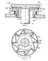
- an end face seal comprises a disc-shaped rotor 1 integral with a rotating shaft 2, and a stator 3 axially movable in an opening in the machine housing 4.
- the rotor rotates within a low-pressure space, e.g. the atmosphere, and is provided with a smooth planar surface 11 opposite a stator surface 31.
- the stator consists of a cylindrical portion 32 and a flange-shaped portion 33, having its upper surface in close proximity to the rotor surface 11.
- the cylindrical portion is slidably movable in the housing 4 and is sealed against penetration of liquid by means of an oil retainer 41.
- Helical springs 5 are mounted between the underside of the flange 37 and the housing 4 and are adapted to urge the stator towards the rotor surface.
- the entire space inside the machine housing and inside the stator is filled by a liquid, at the higher pressure (HP) of the machine; the liquid to be sealed off may be oil, but in the case of pumps it may be water or any other liquid passing through the pump.
- the stator surface 31 is shaped to form eight radial weirs 34 and eight diagonal ridges 35 extending from the outside end of each weir to the inside end of the following weir, assuming that the rotor rotates in the direction of the arrow f.
- Each weir is of a minimum height at its front or upstream edge a and of a maximum height at its rear or downstream edge b. (cf. Figures 6 and 7).
- the stator surface is surrounded by a rim 36 corresponding in height to the maximum height of the weirs and the ridges and serves as a dam on the low-pressure side and as a static seal whenever the machine is stopped, owing to the closure of the gap between rotor and stator by means of the helical springs 5.
- Figures 3 and 4 illustrate a face seal identical with that shown in Figures 1 and 2, but designed for a machine wherein the rotor is in the high-pressure zone, while the machine shaft rotates in the low-pressure zone. It becomes evident from Figure 4 that the weirs and ridges are laid out in the same alignment as in Figure 2, but that the sense of rotation has been reversed from anti-clockwise in Figure 2, to clockwise in Figure 4, that the location of the upstream edges a and downstream edges b have been reversed, and t hat the circular dam 30 is placed along the inner edge of the seal, i.e. on the low-pressure side.
- the shaft seal illustrated in Figures 5 and 7 comprises a shaft 2 having a smooth surface rotating inside a cylindrical stator housing 3 which is fastened inside a machine housing 4.
- the machine housing is filled with oil or another liquid at higher pressure (HP) than the atmospheric pressure (LP) on the outside of the stator.
- HP higher pressure
- LP atmospheric pressure
- the cylinder of the stator housing 3 extends outwardly of the weirs and ridges and terminates in an inwardly projecting collar 36 slightly distanced from the ends of the weirs.
- the collar is of an inner diameter only slightly larger than the shaft diameter and serves as a dam preventing fluid from being thrown out of the seal into the open.
- Figures 6 and 7 show the construction of the stator surface, projected into a plane which comprises spaced-apart weirs 34 and diagonally extending ridges 35 between each two weirs 34.
- the height of the weirs and the direction of their slope is chosen for a shaft velocity v as shown by the arrow.
- the surface velocity of the shaft drags liquid across the weir surface 34 building up a higher pressure than the pressure inside the machine housing if no liquid is to be permitted to penetrate to the outside across the weirs.
- the liquid volume dragged across each weir must be at least equivalent to the volume passing from the high-pressure zone to the low-pressure zone across the gap between the ridge 35 and the rotor surface.
- This volume is composed of two components, one being the volume dragged through this gap by the rotor velocity vector and the other the volume conveyed through the gap by the pressure differential. It is, therefore, of utmost importance to make this gap as small as possible by raising the ridges at least as high as the highest points of the weirs, although similar results will be obtained by lower ridges.
- the pressure diagram of Figure 8 read in conjunction with the section of Figure 7 shows the pressure built up across each weir 34, its maintenance in the high-pressure zone (HP) and the pressure drop across the ridge 35 down to outside pressure (LP). Arrows show the motion of the liquid across the ridges and the weirs.
- HP high-pressure zones
- LP low-pressure zones
- stator surface with several rows of weirs and ridges, a liquid at higher pressure 'can be contained than with a single row.
- a shaft seal there will be two or more rows of weirs and ridges one after the other, while with an end face seal two or more concentric rows will be provided on a stator surface of larger diameter, requiring a rotor of larger diameter as well.
- the action of the hydrodynamic seals of the invention is based on the relative velocity between the rotor and the surface of the weirs and ridges. For this reason it is not absolutely necessary to provide a smooth rotor surface and a stator composed of weirs and ridges, but to reverse these features, by making the stator surface plane and smooth and by providing the ridges and weirs on the rotor.
- the aforedescribed embodiments are advantageous, especially with regard to shaft seals.
Landscapes
- Engineering & Computer Science (AREA)
- General Engineering & Computer Science (AREA)
- Mechanical Engineering (AREA)
- Sealing Using Fluids, Sealing Without Contact, And Removal Of Oil (AREA)
- Turbine Rotor Nozzle Sealing (AREA)
Applications Claiming Priority (2)
| Application Number | Priority Date | Filing Date | Title |
|---|---|---|---|
| IL65289 | 1982-03-19 | ||
| IL65289A IL65289A0 (en) | 1982-03-19 | 1982-03-19 | Hydrodynamic non-contacting seal for rotary machines |
Publications (2)
| Publication Number | Publication Date |
|---|---|
| EP0089698A2 true EP0089698A2 (de) | 1983-09-28 |
| EP0089698A3 EP0089698A3 (de) | 1987-09-16 |
Family
ID=11053348
Family Applications (1)
| Application Number | Title | Priority Date | Filing Date |
|---|---|---|---|
| EP83200087A Withdrawn EP0089698A3 (de) | 1982-03-19 | 1983-01-19 | Hydrodynamische, kontaktlose Dichtung für rotierende Maschinen |
Country Status (5)
| Country | Link |
|---|---|
| US (1) | US4421321A (de) |
| EP (1) | EP0089698A3 (de) |
| JP (1) | JPS58217863A (de) |
| CA (1) | CA1181106A (de) |
| IL (1) | IL65289A0 (de) |
Cited By (1)
| Publication number | Priority date | Publication date | Assignee | Title |
|---|---|---|---|---|
| US6142478A (en) * | 1998-02-06 | 2000-11-07 | John Crane Inc. | Gas lubricated slow speed seal |
Families Citing this family (11)
| Publication number | Priority date | Publication date | Assignee | Title |
|---|---|---|---|---|
| SE453422B (sv) * | 1986-09-15 | 1988-02-01 | Skf Nova Ab | Tetning av axel vid lager eller veggenomgang forsedd med radiellt riktade skovlar |
| US5143384A (en) * | 1989-04-14 | 1992-09-01 | Eg&G Sealol, Inc. | Bi-directional, non-contact face seal |
| GB2231105B (en) * | 1989-04-24 | 1993-04-14 | Sealol | Drained face seal |
| US5000463A (en) * | 1989-10-10 | 1991-03-19 | Hughes Aircraft Company | Shaft seal for systems with intermittent operation |
| US5066026A (en) * | 1990-06-11 | 1991-11-19 | Kaydon Corporation | Gas face seal |
| JPH0756345B2 (ja) * | 1990-07-09 | 1995-06-14 | 株式会社荏原製作所 | 非接触端面シール |
| US6932567B2 (en) * | 2002-12-19 | 2005-08-23 | General Electric Company | Method and apparatus for controlling fluid leakage through gas turbine engines |
| DE102006053165A1 (de) * | 2006-11-09 | 2008-05-15 | Carl Freudenberg Kg | Gleitringdichtung, Gleitringdichtungsanordnung und deren Verwendung |
| US8651496B2 (en) * | 2007-11-28 | 2014-02-18 | Aktiebolaget Skf | Seal |
| US9534502B2 (en) | 2014-03-26 | 2017-01-03 | General Electric Company | Individually compliant segments for split ring hydrodynamic face seal |
| US9611749B2 (en) | 2014-03-26 | 2017-04-04 | General Electric Company | Face seal with locally compliant hydrodynamic pads |
Family Cites Families (9)
| Publication number | Priority date | Publication date | Assignee | Title |
|---|---|---|---|---|
| US3122374A (en) * | 1961-08-17 | 1964-02-25 | Ingersoll Rand Co | Seal for rotating shaft with pressure responsive means |
| US3292847A (en) * | 1964-11-03 | 1966-12-20 | Dresser Ind | Lubricant sealing means for rotary positive displacement pump |
| NL129677C (de) * | 1965-03-17 | |||
| FR1599308A (de) * | 1968-06-08 | 1970-07-15 | ||
| NL160639C (nl) * | 1969-07-22 | 1979-11-15 | Tno | Leger met een gegroefd loopvlak. |
| US3937477A (en) * | 1973-12-26 | 1976-02-10 | Borg-Warner Corporation | Mechanical seal system |
| US4099729A (en) * | 1975-06-18 | 1978-07-11 | Danfoss A/S | Stuffing box backstop ring |
| US4076259A (en) * | 1976-10-29 | 1978-02-28 | Westinghouse Electric Corporation | Static sealing mechanism for liquid natural gas compressors and hydrogen cooled generators |
| US4212475A (en) * | 1979-01-15 | 1980-07-15 | Crane Packing Co. | Self aligning spiral groove face seal |
-
1982
- 1982-03-19 IL IL65289A patent/IL65289A0/xx unknown
-
1983
- 1983-01-19 EP EP83200087A patent/EP0089698A3/de not_active Withdrawn
- 1983-01-24 CA CA000420128A patent/CA1181106A/en not_active Expired
- 1983-03-10 US US06/474,026 patent/US4421321A/en not_active Expired - Fee Related
- 1983-03-18 JP JP58044539A patent/JPS58217863A/ja active Pending
Cited By (1)
| Publication number | Priority date | Publication date | Assignee | Title |
|---|---|---|---|---|
| US6142478A (en) * | 1998-02-06 | 2000-11-07 | John Crane Inc. | Gas lubricated slow speed seal |
Also Published As
| Publication number | Publication date |
|---|---|
| JPS58217863A (ja) | 1983-12-17 |
| US4421321A (en) | 1983-12-20 |
| IL65289A0 (en) | 1982-05-31 |
| CA1181106A (en) | 1985-01-15 |
| EP0089698A3 (de) | 1987-09-16 |
Similar Documents
| Publication | Publication Date | Title |
|---|---|---|
| US4421321A (en) | Hydrodynamic non-contacting seal for rotary machines | |
| US4082296A (en) | Seal for sealing between a rotating member and a housing | |
| US3499653A (en) | Rotary mechanical seal of the gap type | |
| KR101027459B1 (ko) | 축방향 마찰 베어링 | |
| US4257617A (en) | Shaft seal assembly | |
| EP2376822B1 (de) | Segmentierte dichtung mit einem hydrodynamischen merkmal und anordnung | |
| EP3309431B1 (de) | Gleitbauteil | |
| US5980114A (en) | Thrust bearing | |
| US5133562A (en) | Drained face seal | |
| US6155574A (en) | Sealing device | |
| US6106224A (en) | Downthrust pads for submersible centrifugal pumps | |
| US7775528B2 (en) | Bi-directional pattern for dynamic seals | |
| AU639811B2 (en) | Non-contacting gap-type seal having a ring with a patterned microdam seal face | |
| EP0396441A1 (de) | Drehrichtungsunabhängige kontaktlose Gleitringdichtung | |
| EP0595437A1 (de) | Gleitringdichtung | |
| EP0466076A2 (de) | Spiralrillengleitringdichtung | |
| US7322539B2 (en) | Refining surface for a refiner for defibering material containing lignocellulose | |
| CN87100110A (zh) | 离心式密封 | |
| GB1387009A (en) | Rotary shaft seals | |
| US20210381601A1 (en) | Hydrodynamic sealing component and assembly | |
| JPS58190524A (ja) | タ−ボチヤ−ジヤ | |
| US5344163A (en) | Dynamic shaft seal for pumping fibrous slurries | |
| US4570947A (en) | Gas sealing and fluid scavenge apparatus | |
| EP2027404A2 (de) | Bidirektionales muster für dynamische dichtungen | |
| GB2123498A (en) | Sealing bearing cavities |
Legal Events
| Date | Code | Title | Description |
|---|---|---|---|
| PUAI | Public reference made under article 153(3) epc to a published international application that has entered the european phase |
Free format text: ORIGINAL CODE: 0009012 |
|
| AK | Designated contracting states |
Designated state(s): AT BE CH DE FR GB IT LI NL SE |
|
| PUAL | Search report despatched |
Free format text: ORIGINAL CODE: 0009013 |
|
| RHK1 | Main classification (correction) |
Ipc: F16J 15/34 |
|
| AK | Designated contracting states |
Kind code of ref document: A3 Designated state(s): AT BE CH DE FR GB IT LI NL SE |
|
| 17P | Request for examination filed |
Effective date: 19880111 |
|
| 17Q | First examination report despatched |
Effective date: 19881121 |
|
| STAA | Information on the status of an ep patent application or granted ep patent |
Free format text: STATUS: THE APPLICATION IS DEEMED TO BE WITHDRAWN |
|
| 18D | Application deemed to be withdrawn |
Effective date: 19890404 |