EP0089686A2 - Method of and apparatus for printing serial numbers - Google Patents
Method of and apparatus for printing serial numbers Download PDFInfo
- Publication number
- EP0089686A2 EP0089686A2 EP83102857A EP83102857A EP0089686A2 EP 0089686 A2 EP0089686 A2 EP 0089686A2 EP 83102857 A EP83102857 A EP 83102857A EP 83102857 A EP83102857 A EP 83102857A EP 0089686 A2 EP0089686 A2 EP 0089686A2
- Authority
- EP
- European Patent Office
- Prior art keywords
- sheet
- cylinder
- printing
- ink
- blanket
- Prior art date
- Legal status (The legal status is an assumption and is not a legal conclusion. Google has not performed a legal analysis and makes no representation as to the accuracy of the status listed.)
- Granted
Links
Images

Classifications
-
- B—PERFORMING OPERATIONS; TRANSPORTING
- B41—PRINTING; LINING MACHINES; TYPEWRITERS; STAMPS
- B41F—PRINTING MACHINES OR PRESSES
- B41F19/00—Apparatus or machines for carrying out printing operations combined with other operations
- B41F19/02—Apparatus or machines for carrying out printing operations combined with other operations with embossing
-
- B—PERFORMING OPERATIONS; TRANSPORTING
- B41—PRINTING; LINING MACHINES; TYPEWRITERS; STAMPS
- B41F—PRINTING MACHINES OR PRESSES
- B41F13/00—Common details of rotary presses or machines
- B41F13/0032—Auxiliary numbering devices
-
- B—PERFORMING OPERATIONS; TRANSPORTING
- B41—PRINTING; LINING MACHINES; TYPEWRITERS; STAMPS
- B41F—PRINTING MACHINES OR PRESSES
- B41F17/00—Printing apparatus or machines of special types or for particular purposes, not otherwise provided for
-
- B—PERFORMING OPERATIONS; TRANSPORTING
- B41—PRINTING; LINING MACHINES; TYPEWRITERS; STAMPS
- B41F—PRINTING MACHINES OR PRESSES
- B41F19/00—Apparatus or machines for carrying out printing operations combined with other operations
Definitions
- the present invention relates to a method of and an apparatus for printing serial numbers on corners of sheets of value tokens such as bank notes, securities and the like while the value tokens are being printed on the sheets.
- Printing presses used for printing such value tokens are generally equipped with counters for recording the number of revolutions of the press and the number of printed sheets that have passed through the press.
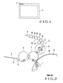
- the printing press also has a serial number printing unit for printing a serial number 2 (Fig. 1 of the accompanying drawings) on a corner of a trimming margin of each printed sheet 1.
- the printed serial number allows an easy and quick determination of how many sheets have been printed during or at the end of the printing process.
- Fig. 2 of the accompanying drawings is a schematic side elevational view of a conventional printing press, showing a serial number printing unit and adjacent parts.
- a sheet 4 fed, one at a time, onto a feedboard 3 from a paper feeder is transported as it is successively gripped by a swing pre-gripper 5 and grippers on transfer cylinders 6, 7 and an impression cylinder 8 which are rotated in the directions of the arrows.
- a desired pattern or image is printed on the sheet 4 between the impression cylinder 8 and a plate or blanket cylinder (not shown).
- the serial number printing unit generally designated by the reference numeral 9, has a numbering device 10 rotatable about its axis in the direction of the arrow for periodical contact with the sheet 4 travelling around the transfer cylinder 7.
- the numbering device 10 is constructed such that its number, which is to be printed on the sheet 4, will increase in a single increment each time the numbering device 10 makes one revolution.
- an inking device 18 comprising an ink fountain 11 for containing ink for printing serial numbers, an ink fountain roller 12, a ductor roller 13, a vibrator roller 14, a transfer roller 15, a vibrator roller 16, and an ink form roller 17.
- a film of ink which is supplied from the inking device 18 to the printing surface of the numbering device 10 is transferred onto a corner of the sheet 4 as it is gripped by the grippers on the transfer cylinder 7 and directed toward the impression cylinder 8, whereupon a serial number is printed on the sheet 4.
- the serial number is printed by the numbering device 10 on the surface of the sheet 4 which will face a blanket 19 on the periphery of the impression cylinder 8 when the sheet 4 is wound on the latter. Therefore, the printed serial number tends to be transferred from the sheet 4 onto the blanket 19 under pressure imposed when a pattern is printed on the sheet 4. The transferred serial number is then transferred from the blanket 19 back onto a next sheet 4 where it bears a newly printed serial number. This difficulty has been eliminated by cutting off the blanket 19 at a position aligned with printed serial numbers to avoid the transfer of the latter from the sheets 4 onto the blanket 19.
- Such a recessed blanket is disadvantageous in that it tends to be placed in a distorted disposition with respect to the impression and to be broken from the recess, resulting in a shorter service life of the blanket 19, and no sharp pattern or image cannot be printed on the sheets 4.
- Another object of the present invention is to provide a method of and an apparatus for printing serial numbers on sheets of value tokens with a reduced amount of labor required for such serial number printing.
- Still another object of the present invention is to provide a method of and an apparatus for printing serial numbers on sheets of value tokens with a high degree of efficiency and a reduced amount of wasted paper.
- an ink-free raised portion is formed on a sheet in a character pattern indicative of a serial number to be printed by pressing type characters on a numbering device.
- ink is applied to the raised portion on the sheet to visualize the serial number.
- a blanket on the impression cylinder has an increased degree of durability as the blanket needs no recess to avoid the transfer of ink from the printed serial number.
- a method of printing a serial number on a sheet comprising the steps of (a) forming an ink-free raised portion on the sheet in a character pattern indicative of the serial number, (b) printing an image pattern on the sheet, and (c) applying ink to said raised portion to visualize said character pattern simultaneously with said printing step (b).
- a method of and an apparatus for printing serial numbers according to the present invention is particularly useful when embodied in a dry-offset printing press which is generally designated by the reference numeral 21 in Fig. 3.
- the printing press 21 basically comprises a paper feeder 22, a printing unit 23, and a paper discharger 24.
- the paper feeder 22 includes a paper pile board 26 for supporting a pile of paper sheets 25 thereon, the paper pile board 26 being automatically elevatable as paper sheets are fed into the printing unit 23.
- a feedboard 27 extends between the paper feeder 22 and the printing unit 23 for receiving the sheets 25 delivered one by one from the paper feeder 22 and for determining sheet registry.
- a swing pre-gripper 28 is positioned at a distal end of the feedboard 27 for gripping the sheet 25 on the feedboard 27 and is swingable to supply the gripped sheet 25 to the printing unit 23.
- the printing unit 23 has an impression cylinder 29, a blanket cylinder 30, and an intaglio cylinder 31 rotatable about their own axes in the directions of the arrows A, B, C, respectively, with lines through the cylinder axes extending substantially perpendicularly to each other.
- the impression and blanket cylinders 29, 30 are held in rolling contact with each other at their peripheral surfaces, and likewise the impression and intaglio cylinders 29, 31 are held in rolling contact with each other at their peripheral surfaces.
- Each of the cylinders has a diameter dimensioned such that four sheets 25 can be printed during one revolution of these cylinders.
- a resilient blanket 33 is wound peripherally around the impression cylinder 29 with an underlay 32 interposed therebetween.
- the impression cylinder 29 has in its outer periphery an axial recess or gap 34 with a plurality of grippers.36 and a plurality of gripper pads 37 disposed therein for gripping an edge of the sheet 25.
- the grippers 36 and the associated gripper pads 37 are supported on a gripper shaft 35 in the recess 34 and a recess wall, respectively, at spaced intervals along the gripper shaft 35.
- the blanket cylinder 30 also has a rubber blanket (not shown) on its outer periphery.
- an intaglio prining plate is mounted on the outer periphery of the intaglio cylinder 31.
- a pair of transfer cylinders 38, 39 held in mutual rolling contact is disposed between the swing pre-gripper 28 and the impression cylinder 29.
- the transfer cylinders 38, 39 have peripheral recesses or gaps 40, 41, respectively, with a plurality of grippers 42, 43 and a plurality of gripper pads 44, 45 disposed therein at axial intervals for grippingly transferring the sheet 25 fed by the swing pre-gripper 28 to the grippers 36 on the impression cylinder 29.
- four plate cylinders 46 for printing four differently colored inks are disposed in rolling contact with the outer periphery of the blanket cylinder 30.
- a movable inker 48 has four ink fountains 47 with four differently colored inks contained therein, groups of rollers (not shown) associated respectively with the ink fountains 47, and four ink form rollers (not shown) associated with the roller groups and held in rolling contact with the plate cylinders 46, respectively.
- Three ink form rollers 49 for applying three differently colored inks are disposed in rolling contact with the outer periphery of the intaglio cylinder 31.
- a movable inker 51 is located behind the ink form rollers 49 and has three ink fountains 50 for supplying three differently colored inks to the ink form rollers 49 through groups of rollers (not illustrated) interposed between the ink form rollers 49 and the ink fountains 50.
- a wiping roller 52 Obliquely beneath the intaglio cylinder 31, there is positioned a wiping roller 52 in rolling contact with the outer periphery of the intaglio cylinder 31 for wiping off excess ink from the printing plate on the intaglio cylinder 31.
- a delivery chain 58 is trained around a sprocket 53 located obliquely upwardly of the impression cylinder 29 and a plurality of sprockets 54, 55, 56, 57 in the paper discharger 24 for transporting the sheet 25 released from the grippers 36 on the impression cylinder 29.
- a pair of paper pile boards 59, 60 is located below an end portion of the delivery chain 58 for receiving alternate stacks of printed sheets 25 that are released downwardly from the delivery chain 58.
- the printing press 21 additionally includes a serial number printing unit.
- the transfer cylinder 39 has a resilient blanket 61 with a thickness of about 1.8 mm extending over a portion of the peripheral surface thereof.
- the blanket 61 has one end held in position by clamping plates 62 with the other end fastened securely to a winding rod 63 so that the blanket 61 is tensioned taut over the peripheral portion of the transfer cylinder 39. Accordingly, any sheet 25 as it is gripped and transported by the grippers 43 is kept against the surface of the blanket 61.
- the serial number printing unit has a numbering device 64 disposed obliquely upwardly of the transfer cylinder 39 and rotatable therewith. The serial number printing unit includes no inking device for supplying ink to the numbering device 64.
- the numbering device 64 has on its distal end projecting type characters 65 including a number which increases in an increment each time the numbering device 64 makes one revolution through the action of an internal number shifting mechanism therein.
- the numbering device 64 and the transfer cylinder 39 are in such a relative phase relationship that the type characters 65 will face the blanket 61 on the transfer cylinder 39 after they have rotated through one complete revolution.
- the type characters 65 are pressed into the sheet 25 to depress the blanket 61 until the sheet 25 is deformed into a raised portion 66 identical in profile to the type characters 65.
- the underlay 32 on the impression cylinder 29 has a hole 67 (Figs.
- Either one of the four plate cylinders 46 includes, in addition to its own pattern plate, a plate surface positioned for transferring a film of ink 68 onto the blanket cylinder 30, from which the ink film 68 is applied to the raised portion 66 of the sheet 25.
- a sheet 25 fed by the paper feeder 22 onto the feedboard 27 is gripped by the swing pre-gripper 28, which is angularly moved to transport the sheet 25.
- the sheet 25 is gripped successively by the grippers 42, 43 on the transfer cylinders 38, 39, and then by the grippers 36 on the impression cylinder 29.
- the sheet 25 is now wound around and transported by the impression cylinder 29.
- four images or patterns of different colors have already been transferred to the blanket cylinder 30 from the four plate cylinders 46 supplied with inks from the inker 48.
- the four patterns are then printed in the dry-offset printing process on the sheet 25 under pressure between the impression cylinder 29 and the blanket cylinder 30.
- Three-colored images or patterns have already been formed on the intaglio plate on the intaglio cylinder 31 by being supplied with inks from the inker 51 and wiping off excess ink with the wiping roller 52. These patterns are also printed in the intaglio printing process on the same surface of the sheet 25 when the latter is transported between the intaglio cylinder 31 and the impression cylinder 29. The printed sheet 25 is thereafter transported by the delivery chain 58, and stacked onto either one of the paper pile boards 59, 60.
- a serial number is printed on the sheet 25 at the same time that the patterns are printed thereon. More specifically, the type characters 65 of the numbering device 64 as it rotates are pressed into the sheet 25 fed along against the blanket 61 on the transfer cylinder 39. When the type characters 65 are pushed into the sheet 25, the blanket 61 therebelow is depressed to allow the raised portion 66 to be formed in the sheet 25 in the same profile as that of the type characters 65. When the sheet 25 is transported further until the raised portion 66 is held against the blanket cylinder 30 as shown in Fig. 7, the raised portion 66 is pushed down by the blanket cylinder 30 to cause the blanket 33 to be elastically deformed therebelow into the depressed portion 33a.
- the depressed portion 33a enters the hole 67 in the underlay 32, preventing the raised portion 66 from being pressed flatwise.
- the ink film 68 has already been supplied from the inker 51 via one of the plate cylinders 46 to the blanket on the blanket cylinder 30 at a position aligned with the raised portion 66 of the sheet 25.
- the ink film 68 is then transferred from the blanket cylinder 30 onto the raised portion 66.
- a serial number represented by the type characters 65 can be embossed on the corner of the sheet 25. Although the embossed serial number does not look so sharp as the printed patterns, it is clear enough to allow a sufficient judgement of how many sheets have been printed in the printing process.
- the numbering device 64 has a known mechanism (not shown) for automatically stopping its counting-up when no printing is effected due to impression throw-off caused by an improperly fed sheet or the like. Therefore, there is no danger for the current serial number to disagree with the number of sheets which have been printed.
- the blanket 61 on the transfer cylinder 39 is kept taut by the clamping plates 62 and the winding rod 63, the blanket 61 may be fastened in position by screws or may be replaced with a narrower strip of blanket attached by a double- sided adhesive tape to the periphery of the transfer cylinder 39 and having a width large enough to cover only any serial numbers to be printed.
Abstract
Description
- The present invention relates to a method of and an apparatus for printing serial numbers on corners of sheets of value tokens such as bank notes, securities and the like while the value tokens are being printed on the sheets.
- It is of prime importance in the printing of value tokens such as bank notes, securities, postage stamps and the like that a record be made of how many value tokens have been printed. Printing presses used for printing such value tokens are generally equipped with counters for recording the number of revolutions of the press and the number of printed sheets that have passed through the press. The printing press also has a serial number printing unit for printing a serial number 2 (Fig. 1 of the accompanying drawings) on a corner of a trimming margin of each printed sheet 1. The printed serial number allows an easy and quick determination of how many sheets have been printed during or at the end of the printing process.
- Fig. 2 of the accompanying drawings is a schematic side elevational view of a conventional printing press, showing a serial number printing unit and adjacent parts. A sheet 4 fed, one at a time, onto a
feedboard 3 from a paper feeder is transported as it is successively gripped by a swing pre-gripper 5 and grippers ontransfer cylinders impression cylinder 8 which are rotated in the directions of the arrows. A desired pattern or image is printed on the sheet 4 between theimpression cylinder 8 and a plate or blanket cylinder (not shown). The serial number printing unit, generally designated by thereference numeral 9, has anumbering device 10 rotatable about its axis in the direction of the arrow for periodical contact with the sheet 4 travelling around thetransfer cylinder 7. Thenumbering device 10 is constructed such that its number, which is to be printed on the sheet 4, will increase in a single increment each time thenumbering device 10 makes one revolution. Above thenumbering device 10, there is provided aninking device 18 comprising anink fountain 11 for containing ink for printing serial numbers, anink fountain roller 12, aductor roller 13, avibrator roller 14, atransfer roller 15, avibrator roller 16, and anink form roller 17. A film of ink which is supplied from theinking device 18 to the printing surface of thenumbering device 10 is transferred onto a corner of the sheet 4 as it is gripped by the grippers on thetransfer cylinder 7 and directed toward theimpression cylinder 8, whereupon a serial number is printed on the sheet 4. - With the prior serial
number printing unit 9, the serial number is printed by thenumbering device 10 on the surface of the sheet 4 which will face ablanket 19 on the periphery of theimpression cylinder 8 when the sheet 4 is wound on the latter. Therefore, the printed serial number tends to be transferred from the sheet 4 onto theblanket 19 under pressure imposed when a pattern is printed on the sheet 4. The transferred serial number is then transferred from theblanket 19 back onto a next sheet 4 where it bears a newly printed serial number. This difficulty has been eliminated by cutting off theblanket 19 at a position aligned with printed serial numbers to avoid the transfer of the latter from the sheets 4 onto theblanket 19. Such a recessed blanket, however, is disadvantageous in that it tends to be placed in a distorted disposition with respect to the impression and to be broken from the recess, resulting in a shorter service life of theblanket 19, and no sharp pattern or image cannot be printed on the sheets 4. - It is an object of the present invention to provide an apparatus for printing serial numbers on sheets of value tokens, which includes no inking device for the serial number printing and hence is simple in structure and inexpensive to construct.
- Another object of the present invention is to provide a method of and an apparatus for printing serial numbers on sheets of value tokens with a reduced amount of labor required for such serial number printing.
- Still another object of the present invention is to provide a method of and an apparatus for printing serial numbers on sheets of value tokens with a high degree of efficiency and a reduced amount of wasted paper.
- According to the present invention, an ink-free raised portion is formed on a sheet in a character pattern indicative of a serial number to be printed by pressing type characters on a numbering device. At the same time that an image pattern is printed on the sheet, ink is applied to the raised portion on the sheet to visualize the serial number. With the arrangement of the invention, no inking device is necessary for the numbering device, and hence the overall apparatus is simple in structure and easy to maintain and service. Since no inking device is provided for the numbering device, there is no need for maintaining ink for the numbering device, for keeping ink roller pressure, and for cleaning the type characters on the numbering device, processes which would otherwise be required. Therefore, it is less frequent to shut down the printing press for the maintenance and servicing of the numbering device. A blanket on the impression cylinder has an increased degree of durability as the blanket needs no recess to avoid the transfer of ink from the printed serial number. According to one aspect of the present invention, there is provided a method of printing a serial number on a sheet, comprising the steps of (a) forming an ink-free raised portion on the sheet in a character pattern indicative of the serial number, (b) printing an image pattern on the sheet, and (c) applying ink to said raised portion to visualize said character pattern simultaneously with said printing step (b).
- The above and other objects, features and advantages of the present invention will become more apparent from the following description when taken in conjunction with the accompanying drawings in which a preferred embodiment of the present invention is shown by way of illustrative example, wherein
- Fig. 1 is a plan view of a sheet on which a serial number is printed;
- Fig. 2 is a fragmentary side elevational view of a conventional printing press with a serial number printing unit;
- Fig. 3 is a side elevational view of a dry-offset printing press in which a method of and an apparatus for printing serial numbers according to the present invention areincorporated;
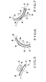
- Fig. 4 is an enlarged fragmentary side elevational view of a numbering device and adjacent parts in the printing press shown in Fig. 3;
- Fig. 5 is an enlarged fragmentary cross-sectional view of a transfer cylinder and associated components in the printing press of Fig. 3;
- Fig. 6 is an enlarged fragmentary cross-sectional view of an impression cylinder and parts on its peripheral surface in the printing press of Fig. 3; and
- Fig. 7 is an enlarged fragmentary cross-sectional view of the impression cylinder and a blanket cylinder in the printing press illustrated in Fig. 3.
- A method of and an apparatus for printing serial numbers according to the present invention is particularly useful when embodied in a dry-offset printing press which is generally designated by the reference numeral 21 in Fig. 3. The printing press 21 basically comprises a
paper feeder 22, a printing unit 23, and a paper discharger 24. Thepaper feeder 22 includes apaper pile board 26 for supporting a pile ofpaper sheets 25 thereon, thepaper pile board 26 being automatically elevatable as paper sheets are fed into the printing unit 23. Afeedboard 27 extends between thepaper feeder 22 and the printing unit 23 for receiving thesheets 25 delivered one by one from thepaper feeder 22 and for determining sheet registry. A swing pre-gripper 28 is positioned at a distal end of thefeedboard 27 for gripping thesheet 25 on thefeedboard 27 and is swingable to supply the grippedsheet 25 to the printing unit 23. - The printing unit 23 has an
impression cylinder 29, ablanket cylinder 30, and anintaglio cylinder 31 rotatable about their own axes in the directions of the arrows A, B, C, respectively, with lines through the cylinder axes extending substantially perpendicularly to each other. The impression andblanket cylinders intaglio cylinders sheets 25 can be printed during one revolution of these cylinders. As shown in Fig. 4, aresilient blanket 33 is wound peripherally around theimpression cylinder 29 with anunderlay 32 interposed therebetween. Theimpression cylinder 29 has in its outer periphery an axial recess orgap 34 with a plurality of grippers.36 and a plurality ofgripper pads 37 disposed therein for gripping an edge of thesheet 25. Thegrippers 36 and the associatedgripper pads 37 are supported on agripper shaft 35 in therecess 34 and a recess wall, respectively, at spaced intervals along thegripper shaft 35. Theblanket cylinder 30 also has a rubber blanket (not shown) on its outer periphery. Although not shown, an intaglio prining plate is mounted on the outer periphery of theintaglio cylinder 31. - A pair of
transfer cylinders impression cylinder 29. Thetransfer cylinders gaps grippers gripper pads 44, 45 disposed therein at axial intervals for grippingly transferring thesheet 25 fed by the swing pre-gripper 28 to thegrippers 36 on theimpression cylinder 29. As illustrated in Fig. 3, fourplate cylinders 46 for printing four differently colored inks are disposed in rolling contact with the outer periphery of theblanket cylinder 30. Amovable inker 48 has fourink fountains 47 with four differently colored inks contained therein, groups of rollers (not shown) associated respectively with theink fountains 47, and four ink form rollers (not shown) associated with the roller groups and held in rolling contact with theplate cylinders 46, respectively. Threeink form rollers 49 for applying three differently colored inks are disposed in rolling contact with the outer periphery of theintaglio cylinder 31. Amovable inker 51 is located behind theink form rollers 49 and has threeink fountains 50 for supplying three differently colored inks to theink form rollers 49 through groups of rollers (not illustrated) interposed between theink form rollers 49 and theink fountains 50. Obliquely beneath theintaglio cylinder 31, there is positioned awiping roller 52 in rolling contact with the outer periphery of theintaglio cylinder 31 for wiping off excess ink from the printing plate on theintaglio cylinder 31. - A
delivery chain 58 is trained around asprocket 53 located obliquely upwardly of theimpression cylinder 29 and a plurality ofsprockets sheet 25 released from thegrippers 36 on theimpression cylinder 29. A pair ofpaper pile boards delivery chain 58 for receiving alternate stacks of printedsheets 25 that are released downwardly from thedelivery chain 58. - The printing press 21 additionally includes a serial number printing unit. The
transfer cylinder 39 has aresilient blanket 61 with a thickness of about 1.8 mm extending over a portion of the peripheral surface thereof. Theblanket 61 has one end held in position byclamping plates 62 with the other end fastened securely to a windingrod 63 so that theblanket 61 is tensioned taut over the peripheral portion of thetransfer cylinder 39. Accordingly, anysheet 25 as it is gripped and transported by thegrippers 43 is kept against the surface of theblanket 61. The serial number printing unit has anumbering device 64 disposed obliquely upwardly of thetransfer cylinder 39 and rotatable therewith. The serial number printing unit includes no inking device for supplying ink to thenumbering device 64. Thenumbering device 64 has on its distal endprojecting type characters 65 including a number which increases in an increment each time thenumbering device 64 makes one revolution through the action of an internal number shifting mechanism therein. Thenumbering device 64 and thetransfer cylinder 39 are in such a relative phase relationship that thetype characters 65 will face theblanket 61 on thetransfer cylinder 39 after they have rotated through one complete revolution. When brought into confronting relation to thesheet 25 on theblanket 61, thetype characters 65 are pressed into thesheet 25 to depress theblanket 61 until thesheet 25 is deformed into a raisedportion 66 identical in profile to thetype characters 65. Theunderlay 32 on theimpression cylinder 29 has a hole 67 (Figs. 6 and 7) positioned in alignment with the raisedportion 66 of thesheet 25 as it is placed on theimpression cylinder 29. Thehole 67 in theunderlay 32 serves, as best shown in Fig. 7, to relieve adepressed portion 33a of theblanket 33 which is resiliently pushed in when the raisedportion 66 of thesheet 25 is displaced radially inwardly under pressure imposed between the impression andblanket cylinders plate cylinders 46 includes, in addition to its own pattern plate, a plate surface positioned for transferring a film ofink 68 onto theblanket cylinder 30, from which theink film 68 is applied to the raisedportion 66 of thesheet 25. - Printing operation of the printing press 21, and a simultaneous serial number printing process will now be described. A
sheet 25 fed by thepaper feeder 22 onto thefeedboard 27 is gripped by theswing pre-gripper 28, which is angularly moved to transport thesheet 25. Thesheet 25 is gripped successively by thegrippers transfer cylinders grippers 36 on theimpression cylinder 29. Thesheet 25 is now wound around and transported by theimpression cylinder 29. At this time, four images or patterns of different colors have already been transferred to theblanket cylinder 30 from the fourplate cylinders 46 supplied with inks from theinker 48. The four patterns are then printed in the dry-offset printing process on thesheet 25 under pressure between theimpression cylinder 29 and theblanket cylinder 30. Three-colored images or patterns have already been formed on the intaglio plate on theintaglio cylinder 31 by being supplied with inks from theinker 51 and wiping off excess ink with the wipingroller 52. These patterns are also printed in the intaglio printing process on the same surface of thesheet 25 when the latter is transported between theintaglio cylinder 31 and theimpression cylinder 29. The printedsheet 25 is thereafter transported by thedelivery chain 58, and stacked onto either one of thepaper pile boards - A serial number is printed on the
sheet 25 at the same time that the patterns are printed thereon. More specifically, thetype characters 65 of thenumbering device 64 as it rotates are pressed into thesheet 25 fed along against theblanket 61 on thetransfer cylinder 39. When thetype characters 65 are pushed into thesheet 25, theblanket 61 therebelow is depressed to allow the raisedportion 66 to be formed in thesheet 25 in the same profile as that of thetype characters 65. When thesheet 25 is transported further until the raisedportion 66 is held against theblanket cylinder 30 as shown in Fig. 7, the raisedportion 66 is pushed down by theblanket cylinder 30 to cause theblanket 33 to be elastically deformed therebelow into thedepressed portion 33a. Thedepressed portion 33a enters thehole 67 in theunderlay 32, preventing the raisedportion 66 from being pressed flatwise. Simultaneously with the formation ofpatterns 69 on the blanket on theblanket cylinder 30, theink film 68 has already been supplied from theinker 51 via one of theplate cylinders 46 to the blanket on theblanket cylinder 30 at a position aligned with the raisedportion 66 of thesheet 25. As a consequence, theink film 68 is then transferred from theblanket cylinder 30 onto the raisedportion 66. By forming the raisedportion 66 at a prescribed position such as a corner on thesheet 25, a serial number represented by thetype characters 65 can be embossed on the corner of thesheet 25. Although the embossed serial number does not look so sharp as the printed patterns, it is clear enough to allow a sufficient judgement of how many sheets have been printed in the printing process. - The
numbering device 64 has a known mechanism (not shown) for automatically stopping its counting-up when no printing is effected due to impression throw-off caused by an improperly fed sheet or the like. Therefore, there is no danger for the current serial number to disagree with the number of sheets which have been printed. - While in the illustrated embodiment the
blanket 61 on thetransfer cylinder 39 is kept taut by the clampingplates 62 and the windingrod 63, theblanket 61 may be fastened in position by screws or may be replaced with a narrower strip of blanket attached by a double- sided adhesive tape to the periphery of thetransfer cylinder 39 and having a width large enough to cover only any serial numbers to be printed. - Although a certain preferred embodiment has been shown and described, it should be understood that many changes and modifications may be made therein without departing from the scope of the appended claims.
Claims (5)
Priority Applications (1)
| Application Number | Priority Date | Filing Date | Title |
|---|---|---|---|
| AT83102857T ATE31674T1 (en) | 1982-03-24 | 1983-03-22 | METHOD AND APPARATUS FOR PRINTING SERIAL NUMBERS. |
Applications Claiming Priority (2)
| Application Number | Priority Date | Filing Date | Title |
|---|---|---|---|
| JP47691/82 | 1982-03-24 | ||
| JP57047691A JPS58163661A (en) | 1982-03-24 | 1982-03-24 | Printing method and printer for managing number |
Publications (3)
| Publication Number | Publication Date |
|---|---|
| EP0089686A2 true EP0089686A2 (en) | 1983-09-28 |
| EP0089686A3 EP0089686A3 (en) | 1985-05-22 |
| EP0089686B1 EP0089686B1 (en) | 1988-01-07 |
Family
ID=12782308
Family Applications (1)
| Application Number | Title | Priority Date | Filing Date |
|---|---|---|---|
| EP83102857A Expired EP0089686B1 (en) | 1982-03-24 | 1983-03-22 | Method of and apparatus for printing serial numbers |
Country Status (5)
| Country | Link |
|---|---|
| US (1) | US4481878A (en) |
| EP (1) | EP0089686B1 (en) |
| JP (1) | JPS58163661A (en) |
| AT (1) | ATE31674T1 (en) |
| DE (1) | DE3375111D1 (en) |
Families Citing this family (4)
| Publication number | Priority date | Publication date | Assignee | Title |
|---|---|---|---|---|
| US4936214A (en) * | 1987-01-09 | 1990-06-26 | Innovative Graphic Industries | Apparatus for adapting offset duplicator machines to accomodate numbering, printing, scoring, perforating and like device |
| PL1700692T3 (en) * | 2005-03-10 | 2016-05-31 | manroland sheetfed GmbH | Device for transferring imaging layers from a carrier sheet to printing sheets |
| US10754277B2 (en) * | 2016-08-10 | 2020-08-25 | Ball Corporation | Method and apparatus of decorating a metallic container by digital printing to a transfer blanket |
| US10739705B2 (en) | 2016-08-10 | 2020-08-11 | Ball Corporation | Method and apparatus of decorating a metallic container by digital printing to a transfer blanket |
Citations (4)
| Publication number | Priority date | Publication date | Assignee | Title |
|---|---|---|---|---|
| DE1561075A1 (en) * | 1967-05-17 | 1970-01-08 | Heidelberger Druckmasch Ag | Sheet-fed rotary machine for offset and letterset printing with numbering unit |
| DE2114416A1 (en) * | 1971-03-25 | 1972-09-28 | Schnellpressenfabrik Koenig & Bauer AG, 8700 Würzburg | Sheet-fed rotary machine for offset printing with numbering unit |
| DE2223568B1 (en) * | 1972-05-15 | 1973-09-27 | Heidelberger Druckmasch Ag | Numbering device for printing machines |
| DE3114057A1 (en) * | 1980-04-07 | 1982-03-11 | Ryobi Ltd., Fuchu, Hiroshima | NUMBER PRINTING MACHINE FOR AN OFFSET PRESS |
Family Cites Families (10)
| Publication number | Priority date | Publication date | Assignee | Title |
|---|---|---|---|---|
| CA482797A (en) * | 1952-04-29 | Becker Arthur | Machines for embossing and printing webs of paper and other material | |
| US1819793A (en) * | 1928-08-03 | 1931-08-18 | Beveridge Paper Company | Process of decorating paper |
| US1742363A (en) * | 1929-03-13 | 1930-01-07 | Prager Co Inc | Process and machine for manufacturing wall paper and the like |
| US2995081A (en) * | 1959-03-23 | 1961-08-08 | Davidson Corp | Blockout means for printing press |
| US3129662A (en) * | 1961-11-15 | 1964-04-21 | Kimberly Clark Company | Test device |
| US3247785A (en) * | 1963-06-19 | 1966-04-26 | Reynolds Metals Co | Method and apparatus for texture embossing a sheet of material |
| CH496548A (en) * | 1969-03-28 | 1970-09-30 | Heidelberger Druckmasch Ag | Sheet-fed offset printing machine with a numbering device |
| US4024812A (en) * | 1972-05-02 | 1977-05-24 | Heidelberger Druckmaschinen Aktiengesellschaft | Removable numbering and imprinting device for sheet-fed offset machines |
| JPS5830434B2 (en) * | 1975-07-08 | 1983-06-29 | 凸版印刷株式会社 | embossed stencil |
| DE2853901C2 (en) * | 1978-12-14 | 1982-10-28 | M.A.N.- Roland Druckmaschinen AG, 6050 Offenbach | Impression device for a printing machine, in particular a rotary printing machine |
-
1982
- 1982-03-24 JP JP57047691A patent/JPS58163661A/en active Granted
-
1983
- 1983-03-17 US US06/476,223 patent/US4481878A/en not_active Expired - Lifetime
- 1983-03-22 DE DE8383102857T patent/DE3375111D1/en not_active Expired
- 1983-03-22 EP EP83102857A patent/EP0089686B1/en not_active Expired
- 1983-03-22 AT AT83102857T patent/ATE31674T1/en active
Patent Citations (4)
| Publication number | Priority date | Publication date | Assignee | Title |
|---|---|---|---|---|
| DE1561075A1 (en) * | 1967-05-17 | 1970-01-08 | Heidelberger Druckmasch Ag | Sheet-fed rotary machine for offset and letterset printing with numbering unit |
| DE2114416A1 (en) * | 1971-03-25 | 1972-09-28 | Schnellpressenfabrik Koenig & Bauer AG, 8700 Würzburg | Sheet-fed rotary machine for offset printing with numbering unit |
| DE2223568B1 (en) * | 1972-05-15 | 1973-09-27 | Heidelberger Druckmasch Ag | Numbering device for printing machines |
| DE3114057A1 (en) * | 1980-04-07 | 1982-03-11 | Ryobi Ltd., Fuchu, Hiroshima | NUMBER PRINTING MACHINE FOR AN OFFSET PRESS |
Also Published As
| Publication number | Publication date |
|---|---|
| EP0089686B1 (en) | 1988-01-07 |
| DE3375111D1 (en) | 1988-02-11 |
| US4481878A (en) | 1984-11-13 |
| JPH0258108B2 (en) | 1990-12-06 |
| ATE31674T1 (en) | 1988-01-15 |
| JPS58163661A (en) | 1983-09-28 |
| EP0089686A3 (en) | 1985-05-22 |
Similar Documents
| Publication | Publication Date | Title |
|---|---|---|
| US7806051B2 (en) | Drive of the inking unit in an intaglio printing machine | |
| US8087440B2 (en) | Embossing device | |
| EP0176702B1 (en) | Intaglio printing machine | |
| US6293193B1 (en) | Method for printing sheets | |
| US4441423A (en) | Collect-printing unit for security printing for use in a rotary printing press | |
| US4479431A (en) | Collect-printing unit for security printing for use in a rotary printing press | |
| JPS6427944A (en) | Method of conducting multi-color printing and printer | |
| JP2000127349A (en) | Intaglio printer | |
| EP0982131B1 (en) | Ink unit in an intaglio printing press | |
| JPH0337508B2 (en) | ||
| JP2000514738A (en) | Multicolor sheet printing press | |
| JP4186028B2 (en) | Inspection rotary printing machine | |
| EP0089686B1 (en) | Method of and apparatus for printing serial numbers | |
| US4942813A (en) | Method and apparatus for dry offset intaglio printing | |
| UA72952C2 (en) | Method for production of piles of printed sheets and sheet printing machine | |
| JPH0423006Y2 (en) | ||
| US20070272104A1 (en) | Coating device | |
| US6546862B1 (en) | Method and device for producing a multicolor print | |
| JPH0241412B2 (en) | ||
| JPH0364309B2 (en) | ||
| GB2092069A (en) | Web lithographic press row identifier | |
| JPH03114836A (en) | Polychrome printing machine | |
| US4480544A (en) | High-production rotary offset printing machine | |
| US3049995A (en) | Printing equipment | |
| US6837161B2 (en) | Ink removal method for printing press |
Legal Events
| Date | Code | Title | Description |
|---|---|---|---|
| PUAI | Public reference made under article 153(3) epc to a published international application that has entered the european phase |
Free format text: ORIGINAL CODE: 0009012 |
|
| AK | Designated contracting states |
Designated state(s): AT CH DE FR GB IT LI SE |
|
| PUAL | Search report despatched |
Free format text: ORIGINAL CODE: 0009013 |
|
| AK | Designated contracting states |
Designated state(s): AT CH DE FR GB IT LI SE |
|
| 17P | Request for examination filed |
Effective date: 19850626 |
|
| 17Q | First examination report despatched |
Effective date: 19860625 |
|
| GRAA | (expected) grant |
Free format text: ORIGINAL CODE: 0009210 |
|
| AK | Designated contracting states |
Kind code of ref document: B1 Designated state(s): AT CH DE FR GB IT LI SE |
|
| REF | Corresponds to: |
Ref document number: 31674 Country of ref document: AT Date of ref document: 19880115 Kind code of ref document: T |
|
| REF | Corresponds to: |
Ref document number: 3375111 Country of ref document: DE Date of ref document: 19880211 |
|
| ET | Fr: translation filed | ||
| ITF | It: translation for a ep patent filed |
Owner name: MODIANO & ASSOCIATI S.R.L. |
|
| PLBE | No opposition filed within time limit |
Free format text: ORIGINAL CODE: 0009261 |
|
| STAA | Information on the status of an ep patent application or granted ep patent |
Free format text: STATUS: NO OPPOSITION FILED WITHIN TIME LIMIT |
|
| 26N | No opposition filed | ||
| REG | Reference to a national code |
Ref country code: CH Ref legal event code: PFA Free format text: KOMORI CORPORATION |
|
| ITPR | It: changes in ownership of a european patent |
Owner name: CAMBIO RAGIONE SOCIALE;KOMORI CORPORATION |
|
| ITTA | It: last paid annual fee | ||
| REG | Reference to a national code |
Ref country code: FR Ref legal event code: CD |
|
| PGFP | Annual fee paid to national office [announced via postgrant information from national office to epo] |
Ref country code: FR Payment date: 19931215 Year of fee payment: 12 |
|
| PGFP | Annual fee paid to national office [announced via postgrant information from national office to epo] |
Ref country code: SE Payment date: 19940119 Year of fee payment: 12 |
|
| PGFP | Annual fee paid to national office [announced via postgrant information from national office to epo] |
Ref country code: CH Payment date: 19940125 Year of fee payment: 12 |
|
| PGFP | Annual fee paid to national office [announced via postgrant information from national office to epo] |
Ref country code: AT Payment date: 19940131 Year of fee payment: 12 |
|
| PGFP | Annual fee paid to national office [announced via postgrant information from national office to epo] |
Ref country code: GB Payment date: 19940314 Year of fee payment: 12 |
|
| PGFP | Annual fee paid to national office [announced via postgrant information from national office to epo] |
Ref country code: DE Payment date: 19940331 Year of fee payment: 12 |
|
| EAL | Se: european patent in force in sweden |
Ref document number: 83102857.6 |
|
| PG25 | Lapsed in a contracting state [announced via postgrant information from national office to epo] |
Ref country code: GB Effective date: 19950322 Ref country code: AT Effective date: 19950322 |
|
| PG25 | Lapsed in a contracting state [announced via postgrant information from national office to epo] |
Ref country code: SE Effective date: 19950323 |
|
| PG25 | Lapsed in a contracting state [announced via postgrant information from national office to epo] |
Ref country code: LI Effective date: 19950331 Ref country code: CH Effective date: 19950331 |
|
| GBPC | Gb: european patent ceased through non-payment of renewal fee |
Effective date: 19950322 |
|
| PG25 | Lapsed in a contracting state [announced via postgrant information from national office to epo] |
Ref country code: FR Free format text: LAPSE BECAUSE OF NON-PAYMENT OF DUE FEES Effective date: 19951130 |
|
| REG | Reference to a national code |
Ref country code: CH Ref legal event code: PL |
|
| PG25 | Lapsed in a contracting state [announced via postgrant information from national office to epo] |
Ref country code: DE Effective date: 19951201 |
|
| EUG | Se: european patent has lapsed |
Ref document number: 83102857.6 |
|
| REG | Reference to a national code |
Ref country code: FR Ref legal event code: ST |