EP0089684A2 - Vorrichtung zum Verbinden mehrerer Bahnen mittels kleiner Streifen - Google Patents
Vorrichtung zum Verbinden mehrerer Bahnen mittels kleiner Streifen Download PDFInfo
- Publication number
- EP0089684A2 EP0089684A2 EP83102855A EP83102855A EP0089684A2 EP 0089684 A2 EP0089684 A2 EP 0089684A2 EP 83102855 A EP83102855 A EP 83102855A EP 83102855 A EP83102855 A EP 83102855A EP 0089684 A2 EP0089684 A2 EP 0089684A2
- Authority
- EP
- European Patent Office
- Prior art keywords
- ribbon
- strip
- small
- sheet
- roller
- Prior art date
- Legal status (The legal status is an assumption and is not a legal conclusion. Google has not performed a legal analysis and makes no representation as to the accuracy of the status listed.)
- Granted
Links
Images




Classifications
-
- B—PERFORMING OPERATIONS; TRANSPORTING
- B42—BOOKBINDING; ALBUMS; FILES; SPECIAL PRINTED MATTER
- B42C—BOOKBINDING
- B42C3/00—Making booklets, pads, or form sets from multiple webs
-
- Y—GENERAL TAGGING OF NEW TECHNOLOGICAL DEVELOPMENTS; GENERAL TAGGING OF CROSS-SECTIONAL TECHNOLOGIES SPANNING OVER SEVERAL SECTIONS OF THE IPC; TECHNICAL SUBJECTS COVERED BY FORMER USPC CROSS-REFERENCE ART COLLECTIONS [XRACs] AND DIGESTS
- Y10—TECHNICAL SUBJECTS COVERED BY FORMER USPC
- Y10T—TECHNICAL SUBJECTS COVERED BY FORMER US CLASSIFICATION
- Y10T156/00—Adhesive bonding and miscellaneous chemical manufacture
- Y10T156/10—Methods of surface bonding and/or assembly therefor
- Y10T156/1052—Methods of surface bonding and/or assembly therefor with cutting, punching, tearing or severing
- Y10T156/1062—Prior to assembly
-
- Y—GENERAL TAGGING OF NEW TECHNOLOGICAL DEVELOPMENTS; GENERAL TAGGING OF CROSS-SECTIONAL TECHNOLOGIES SPANNING OVER SEVERAL SECTIONS OF THE IPC; TECHNICAL SUBJECTS COVERED BY FORMER USPC CROSS-REFERENCE ART COLLECTIONS [XRACs] AND DIGESTS
- Y10—TECHNICAL SUBJECTS COVERED BY FORMER USPC
- Y10T—TECHNICAL SUBJECTS COVERED BY FORMER US CLASSIFICATION
- Y10T156/00—Adhesive bonding and miscellaneous chemical manufacture
- Y10T156/12—Surface bonding means and/or assembly means with cutting, punching, piercing, severing or tearing
- Y10T156/1317—Means feeding plural workpieces to be joined
- Y10T156/1322—Severing before bonding or assembling of parts
-
- Y—GENERAL TAGGING OF NEW TECHNOLOGICAL DEVELOPMENTS; GENERAL TAGGING OF CROSS-SECTIONAL TECHNOLOGIES SPANNING OVER SEVERAL SECTIONS OF THE IPC; TECHNICAL SUBJECTS COVERED BY FORMER USPC CROSS-REFERENCE ART COLLECTIONS [XRACs] AND DIGESTS
- Y10—TECHNICAL SUBJECTS COVERED BY FORMER USPC
- Y10T—TECHNICAL SUBJECTS COVERED BY FORMER US CLASSIFICATION
- Y10T156/00—Adhesive bonding and miscellaneous chemical manufacture
- Y10T156/12—Surface bonding means and/or assembly means with cutting, punching, piercing, severing or tearing
- Y10T156/1317—Means feeding plural workpieces to be joined
- Y10T156/1322—Severing before bonding or assembling of parts
- Y10T156/1339—Delivering cut part in sequence to serially conveyed articles
-
- Y—GENERAL TAGGING OF NEW TECHNOLOGICAL DEVELOPMENTS; GENERAL TAGGING OF CROSS-SECTIONAL TECHNOLOGIES SPANNING OVER SEVERAL SECTIONS OF THE IPC; TECHNICAL SUBJECTS COVERED BY FORMER USPC CROSS-REFERENCE ART COLLECTIONS [XRACs] AND DIGESTS
- Y10—TECHNICAL SUBJECTS COVERED BY FORMER USPC
- Y10T—TECHNICAL SUBJECTS COVERED BY FORMER US CLASSIFICATION
- Y10T156/00—Adhesive bonding and miscellaneous chemical manufacture
- Y10T156/12—Surface bonding means and/or assembly means with cutting, punching, piercing, severing or tearing
- Y10T156/1317—Means feeding plural workpieces to be joined
- Y10T156/1343—Cutting indefinite length web after assembly with discrete article
Definitions
- the present finding relates to a device for the insertion of small blocking strips to multiple sheet material and, more specifically, for the insertion of removable small blocking strips to the perforations of laterally punched and coupled forms.
- a widlly used system is based on small ribbons or small paper strips, having adhesive areas provided on one of their surfaces, which are inserted in the mating holes of all the forms coupled to each other, and then folded in a "U" shape, whereby said adhesive areas are engaged with the first and the last form in a position adjacent to the mating holes without interference with the intermediate forms. Consequently, by cutting the small strip at the mating holes,all the forms coupled to each other are caused to be instantaneously set free.
- This system is based onto an automatic machine adapted to grasp the single small strip and insert it in the group of mating holes, it being thereafter U folded as above mentioned.
- the subject machine had to be upstream provided with a hole enlarging device which was operated at predetermined intervals corresponding to the frequency at which the aforesaid small strips were inserted.
- the main purpose of the present invention is that of providing an automatic device for the insertion of small ribbons or strips onto forms, laterally punched and coupled in multiple groups, by which the aforesaid drawbacks are done away with, whereas the advantages of the system as above shortly described are maintained.
- a more specific purpose of the present invention is that of providing a device of the aforesaid type in which the need of the hole enlargement operation at predetermined intervals is eliminated.
- a further purpose of the present invention is that of providing a device of the aforesaid type which is of simple operation, of rugged structure and of easy maintenance, besides permitting the use thereof with whatever type of mechanism for the continous coupling of forms.
- a device for the insertion of small ribbons or strips adapted to be inserted into groups of mating holes of sheet material, laterally punched and coupled in groups, whereby each small ribbon takes a U shape and is secured to the first and to the last sheets of the sheet group by means of adhesive areas as formed onto the small ribbon itself
- the device being characterized by comprising feeding means for a continous ribbon adapted to be cut into the aforesaid small strips, means for the intermittent advancement of said ribbon along a predetermined path, cutting means adapted to engage said ribbon, according to a predetermined and adjustable frequency cross-wise with respect to the said intermittent advancement direction whereby said small strips are cut from said ribbon, supporting means, for said cutting means said supporting means being operated to carry out a first reciprocating motion in a direction perpendicular to said advancement direction of said ribbon, and to carry out a second reciprocating motion, in a plane perpendicular to the direction of said first reciprocating motion and means for the controlled displacement of a continuous strip of sheets coming from a sheet
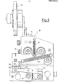
- the device according to the invention includes a casing 10 at the top of which a plate 11 it is provided, an arm 12 being upwardly provided on said plate fitted to rotatably support a roll 14 of ribbon 15, from which i the small strips or ribbons 16 (figures 6 and 7) are to be cut for temporarily blocking the coupled forms.
- the roll 14 is mounted and secured by means of a pair of conventional disks for supporting said roll which are idly mounted on a pin projecting from the arm 12.
- the path of the ribbon 15 is clearly shown by dashed lines in fig. 2 and it advances in the direction of arrows 17.
- the ribbon 15 in its advancement passes around a first roller 18, a guide roller 19 and an intermittently-driving roller 20.
- the roller 18 is journalled onto a pin or fulcrum 21 of a lever 22, one end of which carries a roller 23 engaged with the operating surface 24 of a disk cam which is rotated at a predetermined and adjustable rate by driving means not shown.
- a lever- shaped pawl 27 is provided journalled at the other end of the lever 22, one end of the pawl being joined to a return spring 28, the other end of said spring 28 being anchored to a pin 29 which integrally projects from the lever 22.
- the toothed end 30 of the pawl 27 engages a gear 31 rigidly secured to the advancement roller 20, thus forming an escapement mechanism.
- the ribbon 15 enters a guide 34 provided with a slit 35 through which the ribbon is caused to pass and to protrude by a prefixed lenght with respect to the vertical plane defined by the outer surface of the guide 34.
- a blade 36 is provided having a blade carrier 37, the latter having a spacing plate 38 mounted thereto, the position of which is adjustable by means of a screw 39 with respect to the blade-carrier.
- the plate 38 in turn is slidably mounted to the outer surface of the guide 34, and serves to define the distance from the slit 35, at which the blade 36 engages the protruding portion of the ribbon 15 from the said slit.
- a return spring 40 is secured to the blade-carrier 37, its other end being secured to the casing 10 of the device.
- a second return spring 41 is fixed to the blade-carrier 37, the other end being fixed to the casing 10 for the reasons set forth hereinafter.
- the assembly consisting of the blade 36, the blade carrier 37 and the spacing plate 38 is actuated so as to carry out two concomitantly reciprocating motions namely:
- This roller 42 is journalled at the end of a lever 43 fulcrumed at 44 and undergoing the action of a return spring 45, one end of which is secured to the lever itself whereas the other end is anchored to the casing 10.
- a follower roller 46 is further secured to the lever 43 for engagement with a cam 47 which is driven into rotation, so that the lever 43 is raised or lowered according to a predetermined cycle.
- cams 48 and 49 control the vertical reciprocating motion of the blade-carrier 37, while the cam 50 controls the horizontal reciprocating motion thereof, the rotation rate of the cams being obviously adjustable according to the desired frequency of the corresponding reciprocating motion.
- the small strip 16 is then applied by its portion, which has to be inserted through the group of holes and to be U-folded, to the last sheet of the group of sheets in a flag-like arrangement for the full diameter of the group of holes, so that downstream of the device of the present invention the above stated operation will be carried out by a suitable punch.
Landscapes
- Folding Of Thin Sheet-Like Materials, Special Discharging Devices, And Others (AREA)
- Replacement Of Web Rolls (AREA)
- Perforating, Stamping-Out Or Severing By Means Other Than Cutting (AREA)
Applications Claiming Priority (2)
| Application Number | Priority Date | Filing Date | Title |
|---|---|---|---|
| ITMI1982U21308U IT8221308U1 (it) | 1982-03-24 | 1982-03-24 | Dispositivo applicatore di nastrini di bloccaggio per materiale in fogli multipli. |
| IT2130882U | 1982-03-24 |
Publications (3)
| Publication Number | Publication Date |
|---|---|
| EP0089684A2 true EP0089684A2 (de) | 1983-09-28 |
| EP0089684A3 EP0089684A3 (en) | 1983-10-26 |
| EP0089684B1 EP0089684B1 (de) | 1986-08-27 |
Family
ID=11179864
Family Applications (1)
| Application Number | Title | Priority Date | Filing Date |
|---|---|---|---|
| EP83102855A Expired EP0089684B1 (de) | 1982-03-24 | 1983-03-22 | Vorrichtung zum Verbinden mehrerer Bahnen mittels kleiner Streifen |
Country Status (6)
| Country | Link |
|---|---|
| US (1) | US4525236A (de) |
| EP (1) | EP0089684B1 (de) |
| CH (1) | CH655061A5 (de) |
| DE (1) | DE3365548D1 (de) |
| FR (1) | FR2523937B1 (de) |
| IT (1) | IT8221308U1 (de) |
Cited By (2)
| Publication number | Priority date | Publication date | Assignee | Title |
|---|---|---|---|---|
| EP0250709A3 (en) * | 1986-06-24 | 1989-11-15 | Bodo Brehme | Method and device for attaching together webs of form sets |
| EP0276199A3 (en) * | 1987-01-22 | 1990-03-07 | Officina Meccanica Giuseppe Conti | Feeding device for adhesive strips in binding machines for continuous form sets |
Families Citing this family (2)
| Publication number | Priority date | Publication date | Assignee | Title |
|---|---|---|---|---|
| DE3614791A1 (de) * | 1986-05-02 | 1987-11-05 | Jakob Hans Helmut | Verfahren zum verbinden von drei oder mehr uebereinanderliegenden, stetig transportierten und mit einer transportlochung versehenen bahnen |
| CN116512345B (zh) * | 2023-02-27 | 2024-01-23 | 佐罗科技新材料(江苏)有限公司 | 一种树脂医用胶带生产用分切机构 |
Family Cites Families (4)
| Publication number | Priority date | Publication date | Assignee | Title |
|---|---|---|---|---|
| US3081815A (en) * | 1960-01-21 | 1963-03-19 | Minnesota Mining & Mfg | Taping apparatus |
| US3385747A (en) * | 1964-03-02 | 1968-05-28 | Deering Milliken Res Corp | Textile machine |
| DE1436814A1 (de) * | 1964-12-02 | 1969-01-02 | Imprimex Maschb Ag | Einrichtung zum selbsttaetigen Verbinden der einzelnen Bahnen eines Formularsatzes od.dgl. mittels angeklebter kleiner buegelartiger Laschen |
| DE2205714C2 (de) * | 1972-02-08 | 1974-01-03 | Imprimex Maschinenbau Ag, Zug (Schweiz) | Vorrichtung zum Abschneiden einzelner, jeweils einer Lasche entsprechender Abschnitte von einem in Gestalt eines fortlaufenden Bandes zugeführten Laschenmaterial für die Endlos-Formularsatzherstellung |
-
1982
- 1982-03-24 IT ITMI1982U21308U patent/IT8221308U1/it unknown
-
1983
- 1983-03-21 US US06/477,244 patent/US4525236A/en not_active Expired - Fee Related
- 1983-03-22 EP EP83102855A patent/EP0089684B1/de not_active Expired
- 1983-03-22 DE DE8383102855T patent/DE3365548D1/de not_active Expired
- 1983-03-23 CH CH1577/83A patent/CH655061A5/it not_active IP Right Cessation
- 1983-03-24 FR FR8304860A patent/FR2523937B1/fr not_active Expired
Cited By (2)
| Publication number | Priority date | Publication date | Assignee | Title |
|---|---|---|---|---|
| EP0250709A3 (en) * | 1986-06-24 | 1989-11-15 | Bodo Brehme | Method and device for attaching together webs of form sets |
| EP0276199A3 (en) * | 1987-01-22 | 1990-03-07 | Officina Meccanica Giuseppe Conti | Feeding device for adhesive strips in binding machines for continuous form sets |
Also Published As
| Publication number | Publication date |
|---|---|
| US4525236A (en) | 1985-06-25 |
| EP0089684A3 (en) | 1983-10-26 |
| FR2523937A1 (fr) | 1983-09-30 |
| IT8221308V0 (it) | 1982-03-24 |
| FR2523937B1 (fr) | 1986-11-21 |
| DE3365548D1 (en) | 1986-10-02 |
| CH655061A5 (it) | 1986-03-27 |
| IT8221308U1 (it) | 1983-09-24 |
| EP0089684B1 (de) | 1986-08-27 |
Similar Documents
| Publication | Publication Date | Title |
|---|---|---|
| US4723724A (en) | Web winding machine and method | |
| US1905446A (en) | Film backing paper making machine | |
| US4983155A (en) | Paper web cutter | |
| US4651605A (en) | Double blade rotary cutter apparatus | |
| US4421587A (en) | Label feeder for fan folded documents | |
| US4098056A (en) | Coin passage device of a coin processing machine | |
| CA1073343A (en) | Feeding and cutting device for sheet material | |
| US4525236A (en) | Device for the insertion of small blocking strips or ribbons for multiple sheet material | |
| US3871597A (en) | Labeling apparatus | |
| US4959046A (en) | Apparatus for feeding adhesive coated stitches to continuous forms for binding the forms | |
| US3937452A (en) | Method and apparatus for manufacturing continuous form sets | |
| US3053129A (en) | High speed means for feeding a strip with constant speed input but with intermittent motion at the work location | |
| GB1592465A (en) | Feeding and cutting mechanism | |
| US4209956A (en) | Forming overlapped wrappers | |
| US4409062A (en) | Rotary binder | |
| US4375759A (en) | Variable speed, synchronously operable, stock material feeding and forming apparatus | |
| US3824907A (en) | Synchronized paper web transport and connecting strap cutting and positioning apparatus | |
| US3687347A (en) | Quick change labeling head | |
| GB2169237A (en) | Cutting mechanisms and methods of cutting and stacking record members | |
| EP0036193A1 (de) | Vorrichtung zum Fördern des Bandes von Etikettendruckmaschinen oder ähnlichen Maschinen | |
| JPH0246446B2 (de) | ||
| EP0104149B1 (de) | Stapelvorrichtung von Stückgut in geordnete Schichten | |
| EP0338260A2 (de) | Papierbahnschneidevorrichtung | |
| US4124435A (en) | Label cutting head | |
| US3668962A (en) | Web-cutting apparatus |
Legal Events
| Date | Code | Title | Description |
|---|---|---|---|
| PUAI | Public reference made under article 153(3) epc to a published international application that has entered the european phase |
Free format text: ORIGINAL CODE: 0009012 |
|
| PUAL | Search report despatched |
Free format text: ORIGINAL CODE: 0009013 |
|
| AK | Designated contracting states |
Designated state(s): BE DE GB IT NL |
|
| AK | Designated contracting states |
Designated state(s): BE DE GB IT NL |
|
| 17P | Request for examination filed |
Effective date: 19840126 |
|
| GRAA | (expected) grant |
Free format text: ORIGINAL CODE: 0009210 |
|
| AK | Designated contracting states |
Kind code of ref document: B1 Designated state(s): BE DE GB IT NL |
|
| REF | Corresponds to: |
Ref document number: 3365548 Country of ref document: DE Date of ref document: 19861002 |
|
| ITF | It: translation for a ep patent filed | ||
| PLBI | Opposition filed |
Free format text: ORIGINAL CODE: 0009260 |
|
| 26 | Opposition filed |
Opponent name: GRAPHOTECHNIK JUNG KG Effective date: 19870526 |
|
| NLR1 | Nl: opposition has been filed with the epo |
Opponent name: GRAPHOTECHNIK JUNG KG |
|
| ITTA | It: last paid annual fee | ||
| PGFP | Annual fee paid to national office [announced via postgrant information from national office to epo] |
Ref country code: BE Payment date: 19920217 Year of fee payment: 10 |
|
| PGFP | Annual fee paid to national office [announced via postgrant information from national office to epo] |
Ref country code: GB Payment date: 19920310 Year of fee payment: 10 |
|
| PGFP | Annual fee paid to national office [announced via postgrant information from national office to epo] |
Ref country code: NL Payment date: 19920331 Year of fee payment: 10 |
|
| PG25 | Lapsed in a contracting state [announced via postgrant information from national office to epo] |
Ref country code: GB Effective date: 19930322 |
|
| PGFP | Annual fee paid to national office [announced via postgrant information from national office to epo] |
Ref country code: DE Payment date: 19930329 Year of fee payment: 11 |
|
| PG25 | Lapsed in a contracting state [announced via postgrant information from national office to epo] |
Ref country code: BE Effective date: 19930331 |
|
| BERE | Be: lapsed |
Owner name: BAMA S.P.A. Effective date: 19930331 |
|
| PG25 | Lapsed in a contracting state [announced via postgrant information from national office to epo] |
Ref country code: NL Effective date: 19931001 |
|
| NLV4 | Nl: lapsed or anulled due to non-payment of the annual fee | ||
| GBPC | Gb: european patent ceased through non-payment of renewal fee |
Effective date: 19930322 |
|
| RDAC | Information related to revocation of patent modified |
Free format text: ORIGINAL CODE: 0009299REVO |
|
| RDAG | Patent revoked |
Free format text: ORIGINAL CODE: 0009271 |
|
| STAA | Information on the status of an ep patent application or granted ep patent |
Free format text: STATUS: PATENT REVOKED |
|
| 27W | Patent revoked |
Effective date: 19931215 |
|
| R27W | Patent revoked (corrected) |
Effective date: 19931215 |
|
| APAH | Appeal reference modified |
Free format text: ORIGINAL CODE: EPIDOSCREFNO |