EP0089673B1 - A circuit and a method for processing amplitude and phase variable multiphase signals which are required as current or voltage reference to drive synchronous motors - Google Patents
A circuit and a method for processing amplitude and phase variable multiphase signals which are required as current or voltage reference to drive synchronous motors Download PDFInfo
- Publication number
- EP0089673B1 EP0089673B1 EP83102808A EP83102808A EP0089673B1 EP 0089673 B1 EP0089673 B1 EP 0089673B1 EP 83102808 A EP83102808 A EP 83102808A EP 83102808 A EP83102808 A EP 83102808A EP 0089673 B1 EP0089673 B1 EP 0089673B1
- Authority
- EP
- European Patent Office
- Prior art keywords
- motor
- rotor
- phase
- transducer
- circuit
- Prior art date
- Legal status (The legal status is an assumption and is not a legal conclusion. Google has not performed a legal analysis and makes no representation as to the accuracy of the status listed.)
- Expired
Links
- 230000001360 synchronised effect Effects 0.000 title claims description 18
- 238000000034 method Methods 0.000 title claims description 7
- 238000004804 winding Methods 0.000 claims description 7
- 230000010363 phase shift Effects 0.000 claims 2
- 239000013598 vector Substances 0.000 description 11
- 238000001514 detection method Methods 0.000 description 5
- 230000008569 process Effects 0.000 description 3
- 230000005355 Hall effect Effects 0.000 description 2
- 238000009434 installation Methods 0.000 description 2
- 238000005259 measurement Methods 0.000 description 2
- 238000011144 upstream manufacturing Methods 0.000 description 2
- 230000000712 assembly Effects 0.000 description 1
- 238000000429 assembly Methods 0.000 description 1
- 230000008859 change Effects 0.000 description 1
- 238000010276 construction Methods 0.000 description 1
- 230000008878 coupling Effects 0.000 description 1
- 238000010168 coupling process Methods 0.000 description 1
- 238000005859 coupling reaction Methods 0.000 description 1
- 238000006073 displacement reaction Methods 0.000 description 1
- 230000008030 elimination Effects 0.000 description 1
- 238000003379 elimination reaction Methods 0.000 description 1
- 230000007774 longterm Effects 0.000 description 1
- 238000012423 maintenance Methods 0.000 description 1
- 238000013139 quantization Methods 0.000 description 1
- 230000003068 static effect Effects 0.000 description 1
- 230000009466 transformation Effects 0.000 description 1
- 238000000844 transformation Methods 0.000 description 1
Images


Classifications
-
- H—ELECTRICITY
- H02—GENERATION; CONVERSION OR DISTRIBUTION OF ELECTRIC POWER
- H02P—CONTROL OR REGULATION OF ELECTRIC MOTORS, ELECTRIC GENERATORS OR DYNAMO-ELECTRIC CONVERTERS; CONTROLLING TRANSFORMERS, REACTORS OR CHOKE COILS
- H02P25/00—Arrangements or methods for the control of AC motors characterised by the kind of AC motor or by structural details
- H02P25/02—Arrangements or methods for the control of AC motors characterised by the kind of AC motor or by structural details characterised by the kind of motor
- H02P25/022—Synchronous motors
- H02P25/024—Synchronous motors controlled by supply frequency
Definitions
- This invention relates to a circuit and a method for processing amplitude and phase variable multiphase signals, which are required to drive electric synchronous motors for presetting servosystems, in which the motor is not a D.C. brush motor, but a suitably interlocked synchronous motor.
- the drive of synchronous motors by multiphase alternating current requires that said alternating current varies in amplitude, frequency and phase in order to comply with the magnetic laws of the motor to obtain optimum performances.
- the prior art devices essentially use rotor position sensors which are arranged at particular locations and supply the signals thereby detected to a microprocessor.
- a first system uses "Hall effect cells” as position sensors. This system is quite reliable for high speed rotating motors, but is inadvisable for quality servomotors which are to ensure good performances for speeds in the range from 0.1 up to 6000 r.p.m. Thus, these "Hall effect cells” divide the round angle, and accordingly detect the angular position of the stator, into a limited number of parts. As a result, the angular movement and accordingly the angular rotation of the reference vectors is a step rotation. At high speed, this step rotation is not detected due to the inherent inertias, but at low speed these signals provide a stepped motor operation.
- a second system provides the installation of an incremental encoder.
- the angular position of the rotor magnets can be determined with increased definition. Said definition depends on the accuracy and on the encoder number of divisions. Also in this case, the advancements at very low speed are affected by the quantization of the round angle, whereby the operation would tend to become a pulse operation. Moreover, this is an incremental type of system and auxiliary initial synchronization systems are needed. Finally, the encoder is highly effected by disturbances.
- a third system provides the absolute detection of the angular position of the stator by means of a "resolver" the value of which is then digitized through a quite costly demodulation to obtain a digital value of the angular position to be processed by the micro-processor.
- a fourth system provides the use of shaped cams, the position of which is sensed by suitable magnetic or capacitive sensors.
- the first three devices are extremely complicated, of high cost and provide a step operation rather than a continuous operation since, due to the digital angular detection, the number of angular divisions of the detecting system is limited.
- the fourth system has accuracy limitations. It may be used only for approximate detections of angular position and is strictly bonded to the constructive characteristics of the motor.
- DE-A-2 915 987 discloses a circuit for generating amplitude and phase variable mul- tiphases signals, which are required as current or voltage reference to drive any electric synchronous motor, comprising a multiphase angular position transducer with the same arrangement of poles as the synchronous motor, means for modifying the amplitude of the processed transducer signal and an amplifier supplied with the resultant signals for generating in the motor stator currents of predetermined amplitude and phase to drive said motor, complying with its magnetic laws.
- the transducer is of variable reluctance type and comprises cam means which interact with three core/coil assemblies.
- the motor shaft is provided with a mechanical reference (i.e. a key) which is used to align the polar axis of the motor rotor with the polar axis of the motor stator.
- US-A-3 588 645 describes a system for synchronous motor speed control which uses a transducer comprising two primary windings energizing already processed signals (i.e. two 90° out of phase signals) and three output windings.
- the transducer processes the input signals and the output voltages, induced in secondary windings, which have a sinusoidal modulation at a frequency which is a function of the position of angle sensor rotor, but also of the processed signals which are upstream to the primary windings.
- the circuit according to this application provides that the analog signal from the transducer, for example a synchro is directly utilized by a simple analog processing to generate the multiphase reference signals required by the power amplifier in order to generate the currents in the stator windings determining the required rotating torque.
- resolver type of angular position transducer will be herein referred to a transducer similar to a small rotor acting as a variable coupling transformer, wherein the rotor is wound up in single phase connection and the stator is wound up in three phase connection, that is at 120°.
- a resolver type of angular position transducer differs from a synchro type only in that the stator is wound up according to a two-phase connection at 90°.
- the motor axis 10 is connected to the angular position transducer 11, which has the same polar configuration and number of poles as the motor.
- the transducer 11 is supplied by a medium frequency oscillator device 12, for example at 10 KHz.
- the polar axis of the transducer 11 is mechanically aligned at 90°, as it will be explained in detail, with the rotor polar axis for the three-phase synchronous motor 10.
- the outputs of transducer 11, which in this case are three-phase outputs, for convenience referred to as R, S, T, are then demodulated by the demodulator 13, that is the 10 KHz component is removed.
- the output vectors R1, S1 and T1 which are the resultant of the rotary vectorial system with vectors 120° out of phase in case of a three-phase system (or 90° in case of a two-phase system), but always strictly related to the polar axis of the rotor.
- the angular rotational speed of vectors R1, S1 and T1 is exactly the same as the angular rotational speed of the motor rotor.
- vectorial reference signals are required, such signals being phase and amplitude variable relative to the polar torque (or polar torques) of the motor. Therefore, there is the need of creating currents generating a lead angle polar stator field (which will be herein meant in the same required direction of rotation) if the motor is to be operated as a motor, or a lug polar stator field (in this case meant in opposite direction to the required rotation), when desiring to operate said motor as a generator, with respect to the reference rotor polar axis.
- the transducer be initially mechanically positioned with a polar axis at 90° relative to the polar axis of the rotor, by modalities and means to be explained in detail in the following, it may be conventionally considered that, in case of clockwise rotation R of the motor (that is operating as a motor by supplying a drive couple (CP), the signals R1, S1 and T1 are used as such as current reference, that is without any polarity inversion or phase rotation (situation in Fig. 3A).
- clockwise rotation R of the motor that is operating as a motor by supplying a drive couple (CP)
- the signals R1, S1 and T1 are used as such as current reference, that is without any polarity inversion or phase rotation (situation in Fig. 3A).
- phase shifter device 14 In case of clockwise rotation, when desiring to obtain a plugging couple (operating as generator) it will suffice to invert the polarity of the individual phases (rotating the same through 180°), as shown in Fig. 3B. Figs. 3C and 3D show equivalent situations with anticlockwise rotation.
- M is the polar axis for the motor rotor.
- Polarity inversion is accomplished by the multiplier device 15, in which e1, representing the speed error signal, determines by its sign the vector phase and by its absolute value the modulus or amplitude of the current values or references.
- e1 representing the speed error signal
- e1 may be an error signal referred to any quantity, such as speed, a torque, a pressure and so on.
- Fig. 1 shows e1 which is the result of a comparison made by a comparator 16 between a tachymetrical signal ST and a reference signal RIF.
- Fig. 4 shows a further variant of the circuit according to the invention.
- said multiplier device 15 may be arranged at the beginning of the processing loop upstream the transducer. It modifies the amplitude of the carrier supplied to the transducer 11 and obviously the amplitude of R1, S1 and T1 that are supplied to the phase shifter device as already with modified amplitude.
- this multiplier device can be arranged at any location of the processing loop without the final result being altered.
- An adjustment in the amplitude of the signals supplied to the amplifier 19 can thus be made, so as to accurately adjust the motorspeed, even for very low speeds, of continuous type.
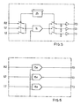
- FIG. 5 A first embodiment is shown in Fig. 5, in which only one multiplying element 15 for the three phases and a multiplexer 25 are used.
- FIG. 6 A second embodiment is shown in Fig. 6, in which as many multiplying elements 15a, 15b and 15c as the phases are used, three in this case.
- Fig. 7 shows the circuit according to the invention in which, by the only transducer provided, in this case a synchro type transducer connected to a (commercially type of) synchro-digital converter 23, in addition to the above mentioned vectorial functions, as required for motor drive, the speed-function and space-function are obtained, that is the absolute measurement of the angle of rotation for the rotor relative to the stator.
- Said system is commonly used for position measurement on tool machines.
- Fig. 8 shows a circuit like that of Fig. 7, in which a two phase resolver transducer 11 is used; the two-phase signals are converted to three-phase signals by means of a Scott transformer SC. For these two last applications the transducer should be of accuracy type. Similar transformations can be provided for multi-phase systems.
- Similar operations can be carried out when availing a three-phase system and desiring to operate in a two-phase or in a multi-phase system.
- the circuit also provides a phase shifter 14 for (conventionally) shifting in delay or logging by 90° the signals R1, S1 and T1 by means of the digital control signal CL. This circuit is shown in Fig. 2A.
- This device is advantageous when desiring to accurately mechanically shift the motor rotor with the transducer, either of synchro or resolver type.
- this circuit can be used with any synchronous motor, of which the angular position of the magnetic poles is not known.
- the same angular transducer is used for phase generation and speed and position detection.
Landscapes
- Engineering & Computer Science (AREA)
- Power Engineering (AREA)
- Control Of Motors That Do Not Use Commutators (AREA)
- Control Of Ac Motors In General (AREA)
Applications Claiming Priority (2)
| Application Number | Priority Date | Filing Date | Title |
|---|---|---|---|
| IT20337/82A IT1151308B (it) | 1982-03-23 | 1982-03-23 | Circuito per la generazione di segnali a piu' fasi,variabili in ampiezza e fase,necessari quale riferimento di corrente o tensione per l'azionamento di motori sincroni |
| IT2033782 | 1982-03-23 |
Publications (2)
| Publication Number | Publication Date |
|---|---|
| EP0089673A1 EP0089673A1 (en) | 1983-09-28 |
| EP0089673B1 true EP0089673B1 (en) | 1987-09-09 |
Family
ID=11165829
Family Applications (1)
| Application Number | Title | Priority Date | Filing Date |
|---|---|---|---|
| EP83102808A Expired EP0089673B1 (en) | 1982-03-23 | 1983-03-22 | A circuit and a method for processing amplitude and phase variable multiphase signals which are required as current or voltage reference to drive synchronous motors |
Country Status (7)
| Country | Link |
|---|---|
| US (1) | US4489266A (it) |
| EP (1) | EP0089673B1 (it) |
| JP (1) | JPS58190294A (it) |
| BR (1) | BR8301555A (it) |
| DE (1) | DE3373598D1 (it) |
| ES (1) | ES8404581A1 (it) |
| IT (1) | IT1151308B (it) |
Families Citing this family (12)
| Publication number | Priority date | Publication date | Assignee | Title |
|---|---|---|---|---|
| JPS60261386A (ja) * | 1984-06-05 | 1985-12-24 | Toshiba Mach Co Ltd | 交流電動機の速度制御装置 |
| CA1283442C (en) * | 1985-12-18 | 1991-04-23 | Senzo Kyutoku | System for driving drum |
| IT1204384B (it) * | 1986-06-06 | 1989-03-01 | Elge App Elettron | Procedimento e apparecchiatura atti a pilotare motori sincroni,in particolare servomotori |
| US4772815A (en) * | 1987-09-15 | 1988-09-20 | Eastern Air Devices, Inc. | Variable refluctance position transducer |
| US5140245A (en) * | 1990-09-24 | 1992-08-18 | Westinghouse Electric Corp. | Pmg-based position sensor and synchronous drive incorporating same |
| US5113125A (en) * | 1991-05-01 | 1992-05-12 | Westinghouse Electric Corp. | AC drive with optimized torque |
| US5763976A (en) * | 1993-12-15 | 1998-06-09 | Parker-Hannifin Corp. | Stator wound resolver with staggered rotor |
| US20070159119A1 (en) * | 2006-01-10 | 2007-07-12 | Caterpillar Inc. | Power system |
| JP5039357B2 (ja) * | 2006-02-14 | 2012-10-03 | 株式会社リコー | ブラシレスモータの駆動制御装置、画像読取装置及び画像形成装置 |
| US10234165B2 (en) * | 2012-07-21 | 2019-03-19 | Zhongshan Broad-Ocean Motor Co., Ltd. | HVAC control system for household central air conditioning |
| JP2015108577A (ja) * | 2013-12-05 | 2015-06-11 | 愛三工業株式会社 | 位置センサ製造方法及び位置センサ |
| US10218378B1 (en) | 2018-08-17 | 2019-02-26 | Robert Bosch Gmbh | Analog converter for motor angle sensor |
Family Cites Families (10)
| Publication number | Priority date | Publication date | Assignee | Title |
|---|---|---|---|---|
| CH492339A (de) * | 1967-03-10 | 1970-06-15 | Bbc Brown Boveri & Cie | Regel- und steuerbare Wechsel- oder Umrichteranordnung zur Speisung eines Wechselstrommotors |
| SE353196B (it) * | 1968-04-19 | 1973-01-22 | Toyo Electric Mfg Co Ltd | |
| US3588645A (en) * | 1968-07-10 | 1971-06-28 | Allis Chalmers Mfg Co | System for controlling magnitude and phase of terminal voltage for adjustable speed synchronous motor |
| US4085355A (en) * | 1976-04-26 | 1978-04-18 | Fradella Richard B | Variable-speed regenerative brushless electric motor and controller system |
| US4259628A (en) * | 1977-08-17 | 1981-03-31 | Kabushiki Kaisha Yaskawa Denki Seisakusho | Control device of AC motor |
| US4358722A (en) * | 1977-08-17 | 1982-11-09 | Kabushiki Kaisha Yaskawa Denki Seisakusho | Speed detector using resolver |
| US4158801A (en) * | 1978-02-07 | 1979-06-19 | Tokyo Shibaura Denki Kabushiki Kaisha | Control system of alternating current motors |
| DE2915987A1 (de) * | 1979-04-20 | 1981-02-26 | Bosch Gmbh Robert | Reaktionsschneller servoantrieb |
| JPS576584A (en) * | 1980-06-12 | 1982-01-13 | Toshiba Mach Co Ltd | Controller for drive of synchronous motor |
| US4382217A (en) * | 1981-05-15 | 1983-05-03 | Gould Inc. | Starting control circuit for an A.C. motor |
-
1982
- 1982-03-23 IT IT20337/82A patent/IT1151308B/it active
-
1983
- 1983-03-18 US US06/476,466 patent/US4489266A/en not_active Expired - Fee Related
- 1983-03-22 ES ES520846A patent/ES8404581A1/es not_active Expired
- 1983-03-22 EP EP83102808A patent/EP0089673B1/en not_active Expired
- 1983-03-22 DE DE8383102808T patent/DE3373598D1/de not_active Expired
- 1983-03-23 JP JP58047352A patent/JPS58190294A/ja active Pending
- 1983-03-23 BR BR8301555A patent/BR8301555A/pt not_active IP Right Cessation
Also Published As
| Publication number | Publication date |
|---|---|
| JPS58190294A (ja) | 1983-11-07 |
| BR8301555A (pt) | 1983-12-06 |
| IT8220337A0 (it) | 1982-03-23 |
| US4489266A (en) | 1984-12-18 |
| ES520846A0 (es) | 1984-04-16 |
| EP0089673A1 (en) | 1983-09-28 |
| IT1151308B (it) | 1986-12-17 |
| ES8404581A1 (es) | 1984-04-16 |
| DE3373598D1 (en) | 1987-10-15 |
Similar Documents
| Publication | Publication Date | Title |
|---|---|---|
| US7301333B2 (en) | Angle position detection apparatus | |
| CA1222298A (en) | Reactance-commutated high resolution servo motor system | |
| US5701065A (en) | Method and apparatus for controlling synchronous motor | |
| US4772815A (en) | Variable refluctance position transducer | |
| EP0089673B1 (en) | A circuit and a method for processing amplitude and phase variable multiphase signals which are required as current or voltage reference to drive synchronous motors | |
| EP0069751B1 (en) | Electric motors | |
| JPH04307306A (ja) | 回転軸の角位置センサー | |
| CA1287898C (en) | Brushless rotary position transducer | |
| EP3982089B1 (en) | Magnetic sensor system for motor control | |
| US4454458A (en) | Synchronous drive for brushless DC motor | |
| US4008425A (en) | Motor servo system with multiplier means to drive and servo the motor | |
| US5349257A (en) | Permanent magnet generator with a position sensing coil | |
| Kieburtz | The step motor--The next advance in control systems | |
| JPS5849093A (ja) | 自始動無ブラシ直流モ−タ | |
| US4659953A (en) | Magnetic structure for synchro and tachometer | |
| JPS6157859A (ja) | シンクロ及び回転速度計の磁気構造 | |
| US5939849A (en) | Motor speed controller | |
| US5920175A (en) | Instantaneous position indicating apparatus for a sensorless switched reluctance machine system | |
| US5376870A (en) | Apparatus for driving a brushless DC motor | |
| JP2021197895A (ja) | 3相ブラシレスモーター及び3相ブラシレスモーターの回転位置検出方法 | |
| US4540925A (en) | Control system for electric motor | |
| US4084118A (en) | Synchrotransmission system controlled by Hall effect | |
| JPS5923198B2 (ja) | 同期電動機の制御方式 | |
| EP0133580A1 (en) | Permanent magnet synchronous motor control system | |
| US3656040A (en) | Self-starting single phase motor |
Legal Events
| Date | Code | Title | Description |
|---|---|---|---|
| PUAI | Public reference made under article 153(3) epc to a published international application that has entered the european phase |
Free format text: ORIGINAL CODE: 0009012 |
|
| AK | Designated contracting states |
Designated state(s): CH DE FR GB IT LI SE |
|
| 17P | Request for examination filed |
Effective date: 19840313 |
|
| 17P | Request for examination filed |
Effective date: 19840313 |
|
| GRAA | (expected) grant |
Free format text: ORIGINAL CODE: 0009210 |
|
| AK | Designated contracting states |
Kind code of ref document: B1 Designated state(s): CH DE FR GB IT LI SE |
|
| REF | Corresponds to: |
Ref document number: 3373598 Country of ref document: DE Date of ref document: 19871015 |
|
| ITF | It: translation for a ep patent filed | ||
| ET | Fr: translation filed | ||
| PLBE | No opposition filed within time limit |
Free format text: ORIGINAL CODE: 0009261 |
|
| STAA | Information on the status of an ep patent application or granted ep patent |
Free format text: STATUS: NO OPPOSITION FILED WITHIN TIME LIMIT |
|
| 26N | No opposition filed | ||
| PGFP | Annual fee paid to national office [announced via postgrant information from national office to epo] |
Ref country code: SE Payment date: 19910228 Year of fee payment: 9 |
|
| PGFP | Annual fee paid to national office [announced via postgrant information from national office to epo] |
Ref country code: CH Payment date: 19910305 Year of fee payment: 9 |
|
| PGFP | Annual fee paid to national office [announced via postgrant information from national office to epo] |
Ref country code: GB Payment date: 19910315 Year of fee payment: 9 |
|
| PGFP | Annual fee paid to national office [announced via postgrant information from national office to epo] |
Ref country code: FR Payment date: 19910329 Year of fee payment: 9 |
|
| ITTA | It: last paid annual fee | ||
| PGFP | Annual fee paid to national office [announced via postgrant information from national office to epo] |
Ref country code: DE Payment date: 19910412 Year of fee payment: 9 |
|
| PG25 | Lapsed in a contracting state [announced via postgrant information from national office to epo] |
Ref country code: GB Effective date: 19920322 |
|
| PG25 | Lapsed in a contracting state [announced via postgrant information from national office to epo] |
Ref country code: SE Effective date: 19920323 |
|
| PG25 | Lapsed in a contracting state [announced via postgrant information from national office to epo] |
Ref country code: LI Effective date: 19920331 Ref country code: CH Effective date: 19920331 |
|
| GBPC | Gb: european patent ceased through non-payment of renewal fee | ||
| PG25 | Lapsed in a contracting state [announced via postgrant information from national office to epo] |
Ref country code: FR Effective date: 19921130 |
|
| REG | Reference to a national code |
Ref country code: CH Ref legal event code: PL |
|
| PG25 | Lapsed in a contracting state [announced via postgrant information from national office to epo] |
Ref country code: DE Effective date: 19921201 |
|
| REG | Reference to a national code |
Ref country code: FR Ref legal event code: ST |
|
| EUG | Se: european patent has lapsed |
Ref document number: 83102808.9 Effective date: 19921005 |